1 - Audio Intervisual Design, Inc.
1 - Audio Intervisual Design, Inc.
1 - Audio Intervisual Design, Inc.

You also want an ePaper? Increase the reach of your titles
YUMPU automatically turns print PDFs into web optimized ePapers that Google loves.
3-6 T HE S ONIC HD3 I/O BOX<br />
Rear-Panel Switches & Connectors<br />
The HD3 rear panel incorporates provisions for connecting it to<br />
SonicStudio and additional converters, assigning it a unique address on the<br />
Sonic bus, and making both digital audio and word sync connections.<br />
WS<br />
16 8 4 2 1<br />
Sonic I/O<br />
In<br />
1-2 Out In 3-4 Out In 5-6 Out In 7-8 Out In<br />
Out<br />
Addr<br />
Digital <strong>Audio</strong><br />
Inputs & Outputs<br />
Word Sync<br />
Input & Output<br />
Address<br />
DIP Switch<br />
Sonic I/O<br />
Connectors<br />
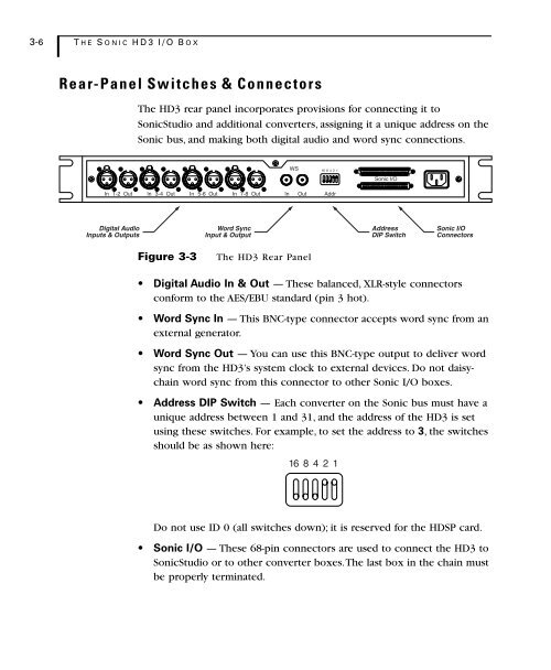
Figure 3-3<br />
The HD3 Rear Panel<br />
• Digital <strong>Audio</strong> In & Out — These balanced, XLR-style connectors<br />
conform to the AES/EBU standard (pin 3 hot).<br />
• Word Sync In — This BNC-type connector accepts word sync from an<br />
external generator.<br />
• Word Sync Out — You can use this BNC-type output to deliver word<br />
sync from the HD3’s system clock to external devices. Do not daisychain<br />
word sync from this connector to other Sonic I/O boxes.<br />
• Address DIP Switch — Each converter on the Sonic bus must have a<br />
unique address between 1 and 31, and the address of the HD3 is set<br />
using these switches. For example, to set the address to 3, the switches<br />
should be as shown here:<br />
16 8 4 2 1<br />
Do not use ID 0 (all switches down); it is reserved for the HDSP card.<br />
• Sonic I/O — These 68-pin connectors are used to connect the HD3 to<br />
SonicStudio or to other converter boxes. The last box in the chain must<br />
be properly terminated.