1 - Audio Intervisual Design, Inc.
1 - Audio Intervisual Design, Inc.
1 - Audio Intervisual Design, Inc.

You also want an ePaper? Increase the reach of your titles
YUMPU automatically turns print PDFs into web optimized ePapers that Google loves.
C ONFIGURING T HE S YSTEM 3-15<br />
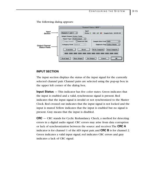
The following dialog appears:<br />
Input<br />
Section<br />
Output Channel<br />
Status Fields<br />
INPUT SECTION<br />
The input section displays the status of the input signal for the currently<br />
selected channel pair. Channel pairs are selected using the pop-up box in<br />
the upper left corner of the dialog box.<br />
Input Status — This indicator has five color states. Green indicates that<br />
the input is enabled and a valid, synchronous signal is present. Red<br />
indicates that the input signal is invalid or not synchronized to the Master<br />
Clock. Red crossed out indicates that the input signal is not locked and the<br />
input is muted. Yellow indicates that the input is enabled but no signal is<br />
present. Gray means that the input is disabled.<br />
CRC — CRC stands for Cyclic Redundancy Check, a method for detecting<br />
errors in a digital audio signal. CRC errors may arise from data corruption<br />
or lack of synchronization between the source and receiver. The CRC A<br />
indicator is for channel 1 of the AES input pair, and CRC B is for channel 2.<br />
Green indicates a valid input signal, red indicates CRC errors and gray<br />
indicates a lack of CRC signal.