HB32 (BG15) - Manuel.. - Free
HB32 (BG15) - Manuel.. - Free
HB32 (BG15) - Manuel.. - Free
- No tags were found...

You also want an ePaper? Increase the reach of your titles
YUMPU automatically turns print PDFs into web optimized ePapers that Google loves.
AUTINORInstallation ManualProgramme: B-<strong>HB32</strong> Version of 30 November 2000
This manual is deemed correct on going to press.The information contained has been scrupulously checked. However AUTINOR declines al1responsibility for error or omission.Should you notice any discrepancy or unclear description, or if you have any suggestions, wewould appreciate your written comments (by mail, fax or Email) to:Société AUTINOR - Service DocumentationZ.A. Les Marlières59710 AVELINS [33] 03-20-62-56-00B [33] 03-20-62-56-41E3 autinor@autinor.comThis manual is the property of AUTINOR, from whom it may be bought (at the above address). Itmay however by freely copied in order to communicate information to those who might need it.We can only authorise a complete copy, without neither addition nor removal ofinformationWhere quotations are taken, the following at least must be noted:- The Company name of AUTINOR,- The number and date of the original edition.ELECTROMAGNETIC COMPATlBlLlTYSince ,the 1st January 1996 al1 lift installations are obliged to respect the essential requirements ofthe European Directive 8913361CEE concerning Electromagnetic Compatibility (EMC).The equipment is only one component of an installation; it is therefore not obliged to show the c
PREAMBLEHandling advice for equipment:Whatever the load, handling operations can be dangerous (collision, dropping, crushing, . . .). Wheneverpossible use mechanical handling rather than manual handling. When manual handling can not be avoided, respectthe rules.At European level, these rules are set out in the Directive 90/269/CEE, Council Directive dated 19 May 1990"concerning minimal heath and safety instructions for manual load handling with risks, to the worker, notably in thelower spinal area ':En France, la réglementation de la manutention manuelle est constituée des textes suivants :Code du travail article R 231-72 (Décret no 92-958 du 3 septembre 1992 transposant en droit français ladirective européenne 92/269/CEE)« Lorsque le recours à la manutention manuelle est inévitable.. . un travailleur ne peut être admis à porterd'une façon habituelle des charges supérieures à 55 kilogrammes qu'à condition d'y avoir été reconnu aptepar le médecin du travail, sans que ces charges puissent être supérieures à 105 kilogrammes. »Décret no 95826 du 30 Juin 1995, Titre le' - article 8 « fixant les prescriptions particulières de sécuritéapplicables aux travaux effectués sur les ascenseurs »+ Circulaire de mise en œuvre DRT 96/3 du 25 Mars 1996« . . . Les travaux comportant le port manuel d'une masse supérieure à 30 kilogrammes, ou comportant la poseou la dépose manuelle d'éléments d'appareils d'une masse supérieure à 50 kilogrammes, . . . doivent êtreeffectués par au moins deux travailleurs ; scomplétée par la norme française NF X 35109 qui donne des recommandations plus précises qui prennent encompte les paramètres suivants : âge du travailleur, nature de la tâche (occasionnelle ou répétitive), charge unitaire,distance parcourue :Load permittedLoad permittedMan 18 145 years 30 kg 25 kgMan 45 1 60 years 25 kg 20 kgSafety measures:Follow the instructions which were given to you by your management when usingindividual protection equipment (gloves, shoes, glasses, restraint harness, etc).
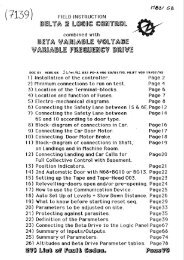
TABLE OF CONTENTSChapter 1 . Generalities ........................................................................................................................How to install the controller cabinet ...........................................................................................Electromagnetic compatibility precautions .................................................................................Minimum connections necessary for initial movement ................................................................Location of terminal blocks .........................................................................................................Location and function of fuses .....................................................................................................Location of led, jumpers and relay ..............................................................................................Controller parameter / diagnostic communication device .....................................................................................................................Concerning the illustratiom (@. @. 4 . .@.h 4)Chapter II . Installation & connecting the safety ..........................................................................Connecting the safety lane with automatic doors and machine room inspection box .................Instruction for wiring any devices to the safety lane ...................................................................Meusurement of the insulation of the safety chain ......................................................................Connecting the doors safety contacts between 6 and 10 .............................................................Chapter III . Installation & connecting in Machine room ...........................................................Connecting in machine room ......................................................................................................Star-delta start of the pump motor ..............................................................................................Direct start of the pump motor ....................................................................................................Thermal protection of thepump motor & control of the machine room temperature .................Connecting of hydraulic units .....................................................................................................Hydraulic unit « GMV martini 3v » « Moris » « Omar » (type 00) .............................................Hydraulic unit « Algi » « Blain » « h&c » (type 01) or « Dover » (type 02) ...............................Hydraulic unit « Beringer » (type 03) .........................................................................................Hydraulic unit « Start elevator » (type 05) ..................................................................................Hydraulic unit « Beringer + Estart » (type 06) ...........................................................................Connecting of emergency valve ...................................................................................................Oil protection against overheating ..............................................................................................Oil level fault (lack of oil) ...........................................................................................................Minimum oil level ........................................................................................................................Viewing of the unlocking zone .....................................................................................................Delayed departure .......................................................................................................................Fault light (indicator) ..................................................................................................................Chapter IV . Installation & connecting in Shaft ............................................................................Limit switch .................................................................................................................................Fixing the slotted-tape brackets ..................................................................................................Fixing the brackets for control of the door-zone .........................................................................Position of the door-zone PO1 sensor orproximity switches (I.L.S.) and tape head 003selector ........................................................................................................................................Position of the vanes for door-zone PO1 sensors in case of movement door open ......................Position of the magnets for the door-zone read byproximity switches .......................................Door securiQ bridge board relevelling pre-opening board,Visualisation of the door-zone (N62)...........................................................................................Door security bridge board relevelling pre-opening board,Visualisation of the door-zone (N57)...........................................................................................
TABLE OF CONTENTSChapter V . Installation & connecting on Landing .....................................................................Connecting on landing: 2 to 8 levels (Sapb or collective 1 button) ..........................................Connecting on landing: Sapb more than 8 levels or collective 1 or 2 buttons / landing to 16levels mmi ...................................................................................................................................Combination of electronics boards .............................................................................................Landing calls for single automatic operation, 2 to 8 levels .........................................................Landing calls for single automatic operation, 2 to 16 levels .................... . ......................Landing calls for collective operation, 1 button, 2 to 8 levels .....................................................Landing calls for collective operation, 1 button, 2 to 16 levels ...................................................Landing calls for full collective operation, 2 to 16 levels .................. ..... .........................Double selective service landing calls .........................................................................................Id 30 model, landing position indicator ......................................................................................Id 50-1 model, landing position indicator .................................................................................Id 50 model, landingposition indicator ......................................................................................Idj30 / 50 model, landing position indicator with arrows ........................ ........................Standard programming ...........................................................................................................Idj 30 / 50 md model. landingposition indicator with scrolling messages arrows ....................Position indicator with scrolling messages arrows programming ..............................................FI 30 / 50 model. landing direction arrows .................................................................................Mode1 with light less than to 1. 2 W (total 2. 4 W mm). landing direction arrows ......................Mode1 with light superior to 1. 2 W (total 2. 4 W mm). landing direction arrows ......................Next departure arrows .................................................................................................................Landing selective gong ................................................................................................................Landing out of service light .........................................................................................................Landing « Engaged » light ..........................................................................................................Chapter VI . Installation & connecting in Car ...............................................................................Connecting in car: 2 to 8 levels (Sapb or collective 1 button) ....................................................Connecting in car: Sapb more than 8 levels or collective 1 or 2 buttons / landing. 2 to 16levels ............................................................................................................................................Car calls for single automatic and collective operation. 1 button. 2 to 8 levels .........................Car calls for collective operation 1 or 2 button(s). 2 to 16 levels ...............................................Double selective service car calls ...............................................................................................Connecting of tape head 003-1 & 003-2 for counting with slotted tape ....................................Car alarm button .........................................................................................................................Car stop button ............................................................................................................................Anti-creeps device .......................................................................................................................Car gong ......................................................................................................................................Unlocking retiring ramp with direct current ...............................................................................Front door three phase motor .....................................................................................................Rear door three phase motor ....................................................................................................Automatic door motor piloted by retiring ramp ..........................................................................Electronic door control unit OP06 or OP1 1 ...............................................................................Electronic door control unit OP15 ..............................................................................................Id 30 rnodel. car position indicator .................... .. ........................................................Id 50-1 model. car position indicator ..........................................................................................Id 50 model. car position indicator .............................................................................................Idj30 / 50 model. car position indicator with arrows ................................................................
CHAPTER 1GENERALITIES
HB-32-Installation manual Chapter 1 - page 12HOW TO INSTALL THE CONTROLLER CABINETDon't forget than the EN-81-2 Standard 5 6.3.2.1 :6.3.2.1 The dimensions of machine rooms shall be sufficient to permit easy and safe working onequipment, especially the electrical equipment.In particular there shall be provided at least a clear height of 2 m at working areas, and :a) a clear horizontal area in front of the control panels and the cabinets. This area is defined as follows :1) depth, measured from the external surface of the enclosures, at least 0,70 m ;2) width, the greater of the following values : 0,50 m or the full width of the cabinet or panel ;b) a clear horizontal area of at least 0,50 m x 0,60 m for maintenance and inspection of moving parts (ifany) at points where this is necessary and, if need be, manual emergency operation (12.9).
ELECTROMAGNETIC COMPATlBlLlTY PRECAUTIONSCONCERNING THE SET OF WlRlNG IN THE LANDING COLUMN SEPARATION.3 SET OF WlRlNGWARNING:We recommend to separatein the landing column,the 3 sets of wiring in 3 rows:Lighting - Power socketsSafety laneand Low Voltage,in order for ease of maintenance and takingEMC* regards into accountCONCERNING TRAlLlNG CABLE SEPARATION.* EMC: ElectroMagnetic CornpatibilityThe devices controlled by the contactors are powered by wires which go into the trailing cableThe trailing cable's other conductor wires do not transport strong currents to activate power devices, butelectrical "DATA via weak currents. This data could be, for example, the state of the door limits necessary tocontrol the automatic doors, or the car calls.To show you the difference in importance between the two types of current, here is an example: Certaindoor motors can use 3 amps whereas the current used for the data concerning the state of the door limits isonly 3 mA.There is, in this typical example, a ratio of 1 to 1000.This ratio is often even greater, especially when you consider the starting current of a power device whenit is first switched on. It is clear that the big currents will influence the little ones if care is not taken to separatethem.IF THESE CURRENTS IN THE TRAlLlNG CABLE ARE NOT SEPARATED:FALSE DATA WlLL BE SENT TO THE CONTROLLER,THERE WlLL BE GRADUAL DETERIORATION OF THE ELECTRONIC COMPONENTS (ANYTHING FROM 3DAYS TO A FEW MONTHS).THE SHORT OR MEDIUM TERM CONSEQUENCES WlLL BE SOME "STRANGE" FUNCTlONlNG BY THECONTROLLER, EVENTUALLY CAUSING BREAKDOWNS! ! !TO SUM UP, IT IS ESSENTIAL THAT THE CONDUCTOR WIRES FROM THE TRAlLlNG CABLE CARRYINGSTRONG CURRENTS FOR THE RETlRlNG RAMP, DOOR MOTOR, BRAKING INJECTION, ANTI-CREEPS AND THECAR VENTILATION MOTOR, NOT TO MENTION THE CAR LlGHT AND SAFETY CHAIN, ARE SEPARATED FROMTHE OTHER CONDUCTORS CARRYING WEAK CURRENTS.1 MECANICAL ATTACHMENTS 1ONE OR SEVERAL"WEAK CURRENT"TRAlLlNG CABLETHE TRAlLlNG CABLES MUST BE SEPARATED AS FAR APART AS POSSIBLE AND SHOULD BEARRANGED IN THE SHAFT AS SHOWN BELOW:IF YOU ARE USlNG HALF-WAY BOXES, YOU SHOULD ALSO TAKE CARE TO SEPARATE THE WIRES.The precautions carried out above should be taken in the controller as well. In fact, you should avoidcrossing wires in al1 directions behind the controller and should leave a little slack to aid maintenance.
HB-32 Installation manual Chapter 1 - page 14MINIMUM CONNECTIONS NECESSARYFOR INITIAL MOVEMENT (112)ROOM INSPECTION OPTIONIS PROGRAMMED "OPTMAN"MUST BE PROGRAMMED - ON -hvl 70FlllxG$M @me. 112 1.0*STATE OF THESAFETY LANETHE 3 LEDs (6,8 & 10)NEED TO BE LIT UPBEFORE THE LlFTWlLL MOVECOM~ELECTROMECHANICALTERMINAL RAILEARTH COLLECTING BAR101000 G30000 0000101Minimum connection necessary for initial movement - hydraulic with slotted tape
HB-32 Installation manual Chapter 1 - page 15MINIMUM CONNECTIONS NECESSARYFOR INITIAL MOVEMENT (212)During the construction phase, you can temporarily use the OV, GM and GD inputs on the KM12connector for running up and down respectively.CHECK THAT THE MACHINE ROOM INSPECTION OPTION IS PROGRAMMED - "OPTMAN"MUST BE PROGRAMMED ON AT ADDRESS 07 - SEGMENT 4CONNECT AS FOLLOWS:(See page 14 for where to make these connections)Connect the thermistor andlor the pump motor safety thermo-contact between@ the STH and OVterminals on the KM11 connector.@ Temporarilv bridge OVand INS on the KC23 connectorThe "up" and "down" push buttons on the inspection box on the car roof to the@ GM, GD and OVterminals on the KM12 connector.(4) The safety circuits IS, 6, 8 and 10 on the electromechanical terminal railThe pump motor to U1, VI, W1 and U2, V2, W2 on the electromechanical@ temina rail, and Eatth to the eatth collecting bar.The electrovalves to the KHI connector on the BG16; note that certain@ hydraulic power units require connections to the electromechanical terminal rail.The power supply to LI, L2, L3 and Neutra1 if available, Eatth to the eatth@ collecting bar.Temporarilv bridge CS1 and OV on KA13 and possibly CS2 and OV on KA16 of@ the BGID board (when there are 2 door operators).When there is a mechanical anti-creep temporarilv bridge the anti-creep inputs,OV, TAQI, and TAQZ on KC31 connector of ,the BG16 board. If there is only(g\) one anti-creep, bridge between the TAQI and TAQZ inputs.w Note that if you are using anti-creeps, the anti-creep (TAQUET) option (address 5Csegment O) should be ON.The oil thermostat, if there is one, between MTH and OV on KM17, if nottemporarilv bridge MTH and O".
24R@ 4 FLOORS COLLECTIVE @ UP TO 8 FLOORS @ NOTHING TO BE CONNECTED
HB-32 Installation manual Chapter 1 - page 17LOCATION AND FUNCTION OF FUSESfor FU2 and FU56PA8E RU%for FUI5A-250V dim: 5x20 TIME LAGPOWER SUPPLYPROTECTION5A-250 V dim: 5 X 20 TlME LAGSAFETY LANEFU1ELECTRONICAND SIGNALPOWER SUPPLYPROTECTION5A-250V dim: 5 x 20 TlME LAGFU524RB, PROTECTION WlREFOR CALL PANEL BUTTONS2,5A-250V dim: 5 x 20 QUlCK ACTINGFU2COMB, PROTECTION WlREFOR CALL PANEL BUTTONSPOWER SUPPLYPROTECTION2A-250 V dim: 5 X 20 TlME LAG $mR&#os&for FU1 & FU7.for FU2 & FU3 ifELECTRONIC2,5A-250V dim: 5 x 20 QUlCK ACTINGType 1 transformer5A-250V dim: 5x20 TlME LAGYELLOW LEDRECTlFlEDCURRENTPRESENT(brake, retiring ramp,electrovalves, anti-creep ...)for FU2 & FU3 ifType 2 transformer2A-250V dim: 5x20 TlME LAGFU7RECTlFlEDCURRENTPROTECTIONTYPE A5A-250V dim: 5 x 20 TlME LAGIFU1BH07BOXPROTECTION5A-250V dim: 5 x 20 TlME LAG\LI PA-L2PA-L3PAL3P DOOR 1 AND DOOR 2LI P-L2P PROTECTION OF PROTECTIONPRIMARY CONTROLLER THE THlRD PHASE OF THE INPUT PHASESTRANSFORMER FOR THE PHASE-FAIL FOR THE DOOR MOTORPROTECTION CONTROLLER OPTION OPERATOR 14A-380V dim: 8,5 x 31,5 2A-380V dim: 8,5 x 31,5 2A-380V dim: 8,5 x 313
HB-32 Installation manual Chapter 1 - page 18LOCATION OF LED, JUMPERS AND RELAYOF THE <strong>BG15</strong> AND BG16 BOARDS
HB-32 Installation manual Chapter 1 - page 19FUNCTION OF THE SWI, SW2, SW4-SW5, SW7, SW9SW10-SWl1& SW12 JUMPERS OF THE <strong>BG15</strong> BOARDmSW1mSW2sw31 1SW4 SW5When the jumper is present, 24V increase the mass relays.When the jumper is present, OV increases the mass relays.DOES NOT EXIST.When the jumpers are in the lower (position 1-2) the controller isprogrammed for use with the P202U tape-head.1SW4 SW5SW6When the jumpers are in the upper (position 2-3) the controller isprogrammed for use with the 003 tape-head or the 1.L.S proximity switches.DOES NOT EXIST.When the jumper is in the lower (position HYDR) the controller isprogrammed for use as a HYDRAULIC.SW7SW7sw81 2 3rnSWlO rnSWllSW12When the jumper is in the upper (position TRAC) the controller isprogrammed for use as a TRACTION.DOES NOT EXIST.Place the jumper to the right (position 2-3) for a single button - 2 to 8 floorsusing on the <strong>BG15</strong> board only.swsSW1OSWllSW121 2 3Place the jumper to the left (position 1-2) for al1 other situations.
HB-32 Installation manual Chapter 1 - page 20CONTROLLER PARAMETER I DIAGNOSTICCOMMUNICATION DEVICEMODlFBG17\ 1IndicatorparameteraccessFigure 1 Position of the sliding switches for parameter modeFigure 2 Position of the communication device
HB-32 Installation manual Chapter 1 - page 21THE PARAMETERS AND THElR MYSTERIESThis chapter contains information which will allow you to adapt theHB-32 equipment to the specific conditions of the lift on which it is installed.This adaptation is controlled by parameters, which you can modify according to your needsusing the removable parameter / diagnostic1 communication device as described below inthe paragraph Accessing the parameters.The parameters are memorised in a particular type of memory called an EEPROM (orE2PROM) which keeps the information even when the equipment is switched off.Each parameter is linked to an abridged name and an address which corresponds to theposition at which it is memorised in the EEPROM chip. As computers are strange creatures,the addresses are expressed in a particular numbering system, called an hexadecimalsystem (= a numbering system in base 16), which is made up of numbers (from O to 9) aswell as letters (A to F). This peculiarity aside, you only need to consider the address as amarker (think of the game of battleships).Accessing the parametersAs mentioned above, you can see and modify the parameters using theparameterldiagnostic communication tool; this consists of a BG17 circuit board, which isplugged into the <strong>BG15</strong> (figure 2, page 20).The BG17 board is made up of 2 displays with 7 segments, 2 push buttons and 2 slidingswitches (figure 1, page 20).To access the parameters, the left-hand sliding switch must be at the bottom; thisposition is shown as PAR (as in PARAMETER) on the board.When the sliding switch is in this position, the decimal point on the right-hand display lightsup to remind you ,that you are looking at or modifying the parameters.1 Note for those used to using Our previous manuals :The term "parameterldiagnostic communication device" replaces the old term "communication tool" toavoid any risk of confusion with the equipment used to communicate (directly or by telephone link) withthe computer system (telesurveillance andlor telediagnostic).
HE-32 Installation manual Chapter 1 - page 22DISPLAY MODESDepending on the information to be displayed, the HB-32 use the most appropriate methodof showing the information.Digit ModeThe digit mode is useful to read or programme times, or the number of floors,of doors for example.Example: If we have 2 door operators, we program 02 at address 03.the numberSegment ModeThe segment mode uses the individual vertical segments on the display as shown below.Segment6 1 , , 1 Segment 5segment 7 1 1 $ Segment41 1 segment 3 Segment CISegment 217Segment 1This mode is useful to activate or deactivate different functions:Example: To activate the "flashing direction arrows" option, segment 5 ataddress 08 must be ON.The segment mode is also useful to view the state of inputs and outputs:Example: To check that the CO input (car cal1 to level O) is correctly read bythe HB-32, you need to look at segment O at address 00.To change from digit to segment mode and vice-versa, slide the ADR-DON-MODIF switchto ADRIDON and press !&I buttons at the same time, and release.
HB-32 Installation manual Chapter 1 - page 23-To chanqe the address or to view the inputs, outputs and parametersADRIDONO Check that the ADRIDON-MODIF switch is on ADRIDON.Q Scroll to the desired address (eg 03) by pressing the push buttons below the display.Press either button and the address will be displayed. Each time you press a button the valuedisplayed will be increased by 1.Press the right hand button 10MODIFtimes to changel-BG17PARfrom address 09 to address 03ECRlT ECRlT1 wLeave the buttons for 1 second, and the contents of the selected address will be displayedindefinitely.MODIFMODIFBG171 second later ...lBG17PARECRlT -1ECRlTTo remind yourself of the current addressIf you forget the address you are at,O Slide the ADRIDON-MODIF switch to MODIF.MODIFIfQ Then slide it back to ADRIDON. This will show you the address for 1second, and then the contents.
-HB-32 Installation manual Chapter 1 - page 24TO CHANGE THE PARAMETERSCheck that the RAM-PAR switch is to PAR.PARA) In digit modeO Go to the parameter address as explained on the page before (e.g. 03).MODIFMODIFlBG17p*R1 second later ...lBG17PAR1 ECRlT 1@ Slide the ADRIDON-MODIF switch to MODIF.ECRITMODIFIfUse the push buttons to increaseldecrease to the new value (e.g. 02).BG17ECRIT -(MODIFPush once on the right-handbuttonto change the value from O1 to&ECRITBG17MODIFRegister the new value by pushing and releasing both buttonsO at the same time.@ Slide the ADRIDON-MODIF switch back to ADRIDON. Address 03 willshow followed by its value 02.ADRIDON
1HB-32 Installation manual Chapter 1 - page 256) In segment modeO Go to the parameter address as previously explained (e.g. 08).-If the contents are displayed as-a figure (82 in the example below), check that the right handswitch is in the upper position, and press both buttons at the same time; this will pass you intosegment mode. The current address will be displayed followed by the contents shown insegments. If not pass ont0 stageRAMPARMODIF @MODlFBG17BG17PressECRITand release ...The left-hand button acts on the TOP ROW ofsegments (4 to 7),TOPROWBOTTOMThe right-hand button acts on the BOTTOMROW of segments (O to 3).OECRITSlide the ADRIDON-MODIF switch to MODIF.lIn Our example we want to activate the "flashing direction arrow"function (address 08 segment 5).We have to light up segment 5 while keeping on al1 other segments intheir present stateflashina direction arrowPress-flashingPressoncedirection arrowBG17MODlFECRIT 1Repeat stages@ and @shown on the previouspage.
HB-32 Installation manual Chapter 1 - page 26CONCERNING THE ILLUSTRATIONS (112)Each connection that you will have to carry out is accompanied by an explication andan illustration. The illustrations try to summarise in one page al1 the important elementswhich will be necessary for you to carry out the corresponding function; i.e.:The PARAMETERS which you need to check or adjust,The CONNECTIONS themselves,The corresponding VARIABLES or INPUTSIOUTPUTS,The CONSEQUENCES of any possible ANOMALY connected with the function inquestion.In order to achieve this goal (or at least to try to) this manual uses the following symbols:A DXXXXXXAdd. YYSeg. ZView of the parameterldiagnostic tool when you should check ormodify a parameter's value. Note that the push buttons areshown in this case. The figure also specifies the position of thesliding switches on the BG17 board.View of the parameterldiagnostic tool when you should check thestate or value of a variable. Note that the push buttons are notshown in this case. The figure also specifies the position of thesliding switches on the BG17 board.Name, address and possible segment number, for the variable orparameter shown in one of the 2 preceding figures.You should check the value or state of the parameter indicated,and of course changes the parameter if it does not correspond tothe value or state indicated.You should adjust the value of the parameter indicated. The unitused (second, 111 0 second, millimetre, etc ...) and the base(decimal or hexadecimal) are displayed.Note: You will find al1 useful information about the bases and theconversions between bases in the chapter dedicated tothe parameters.Don't worry, be happy!The parameter shown is at the right value, or the variable shownreflects a normal operation of the function in question.Now worry!The parameter shown is the wrong value, or the variable shownreflects a breakdown of the function in question.
HB-32 Installation manual Chapter 1 - page 27CONCERNING THE ILLUSTRATIONS (212)aFault!nKeep an eye on this!This symbol indicates that you can see the state of the function inquestion. It is used instead of the "smilies" when there is nocorrect or incorrect state strictly speaking. This would be the casefor example with the contact authorising movements when in fullspeed inspection mode.The wiring of the current function has caused a fault code to bedisplayed on the parameterldiagnostic tool.Permanent fault!This symbol accompanies the above symbol, when the wiring ofthe current function causes the permanent stop of the lift. In thiscase, the only way of putting the lift into service is by anintervention of you (or by cutting the power supply).Fault code!The fault code when there is a problem with the wiring of thecurrent function.
CHAPTER IIINSTALLATION&CONNECTINGTHE SAFETYWARNING!Every intervention, connecting, on site maintenance,in the controller must justified a systematic cut of themain machine room switch provided by theEN 81 standard 5 13.1.1 .l.
HB-32 Installation manual Chapter II - page 3INSTRUCTION FOR CONNECTING ANY DEVICESTOTHESAFETYLANESAFETY LANETOP OVER TRAVEL PRIMARY DOOR DOORLlMlT SAFETY CLOSED LOCKEDCONTACTSCV & RS : HINGED TERMINALS TO TEST THEMAKE SURE THAT ALL OF THE TERMINALSINSULATION OF THE SAFETY LANE ARF CORRECTLY TlGHTENED !-Note : To make this diagram clearer, the electronicinterfaces and the controller have been omitted.Connection of the interfaces to he lift's safety laneThe - O V of the secondary winding of the transformer which powers the safety@ lane must only be connected to the CV hinged terminal, by a wire whosethe colo~ir is neither green and yellow, nor blue.Only the hinged terminal mentioned above should carry the label CV; noother terminal in the controller should have this label.With the exception of movement contactors (connected to the controller@ relays) ALL devices (contactors, electronic interfaces) with a pole connectedto the safety lane, must have their other pole connected uniquely to the RShinged terminal (Reference - - Securities), by a wire whose the colour isneither green and yellow, nor blue.The hinged terminals RS and CV must never be wired together; they must@ be inked to the protection conductor PE by 2 separate wires. whosecolours must be neither green and yellow, nor blue.
HB-32 Installation manual Chapter II - page 4MEASUREMENT OF THE INSULATION OF THE SAFETY CHAINEN 81 standard 5 13.1.3 a), state that the minimum insulation resistance of the safety chain shallbe 500 000 R l:13.1.3 lnsulation resistance of the electrical installation (CENELEC HD 384.6.61 SI)The insulation resistance shall be measured between each live conductor and earth.Minimum values of insulation resistance shall be taken from table 5.Nominal circuit voltageVSELV1 500> 500Test voltage (D.C.)V2505001 O00lnsulation resistanceMSZ2 0,252 0,52 1,OWhen the circuit includes electronic devices, phase and neutral conductors shall be connectedtogether du ring measurement.In order to facilitate the measurement of the insulation resistance of the safety chain ask by EN 81-1Annex D 5 D.2 f) 1) for electric lifts and EN 81-2 Annex D 5 D.2 e) 1) for hydraulic lifts AUTINORcon,trollers are provided with switching terminals named CV and RS.These two are Weidmüller model WTR 2.5, reference 101 110 which electrical characteristics,according IEC 947-7-1 are:Tension 500 V, lntensity 16 A, Section 2,5 mm2For an easy work, the terminals are installed close together on the electromechanical rail and eachterminal have a yellow switching lever; when the two levers are in the off posi,tion, al1 elements of thecon,troller related to the safety chain are disconnected from the earth.TO AVOlD DAMAGE TO ELECTRONICS, PUT THE LEVERS OF THE 2 TERMINALS CV AND RS INTHE OFF POSITION BEFORE MEASURING INSULATION!CV & RS : SWlTCHlNG TERMINALS FORINSULATION OF THE SAFETY CHAIN7cv Li Ul U2AEARTH CONNECTION BARMeasurement of the insulation resistance of the safety chain: example for MB32 controller.These values are the same to those indicated in table 61 A of standard NF C 15-100, identical to the valuesindicated in publication CE1 364-6, not yet harmonised on the level of CENELEC (but which were the subjectof the project of harmonisation PrHD 384-6 in Mars 1990).
HB-32 Installation manual Chapter II - page 5CONNECTION OF THE DOORS SAFETY CONTACTSBETWEEN 6 AND 10 (112)(*) The EN 81 Norm (§ 7.7.4.2) authorizethe using of a unique contactfor the landing in case ofsimultaneaous mechanic trainingof the car and landing doorsDoorClosingContactDoor closing contact andlorlocking of the hinged doors (*)Level n=ALevel mIn case of Car and Landing Automatics doors Connecting-8DoorClosingContactIn case of hinged doors and automatic car door
HB-32 Installation manual Cha~ter II - nage 6CONNECTION OF THE DOORS SAFETY CONTACTSBETWEEN 6 AND 10 (212)(*) The EN 81Norm (5 7.7.4.2) authorizethe using of a unique contactfor the landing in case ofsimultaneaous mechanic trainingof the car and landing doorsDoor closing contacts Contacts of the Door closing contacts andlorof the hinged doors hinged doors locking of the hinged doors (*)-Lw+ *----Level Level Door Level Level Level Leveln m Closing n m n mContactIn case of mixed service automatic car door,hinged doors or automatic at some levelsIII IDoor closing contactsof the hinged doorsDoor locking contactsof the hinged doorsIn case of hinged door without car door (flush shaft)
CHAPTER IIIINSTALLATION&CONNECTINGIN MACHINE ROOM
IGU-+II - -I
STAR-DELTA START OF THE PUMP MOTORDemDirDirect start?Add. 5CSeg. 1 offTDemYDStar-delta starttemporisationAdd. 58 bRAMADRIDONPARMODlFHexb-, "0 Earth motor in the oil tank-&Connecting for the Star-delta start
HB-32 Installation manual Chapter III - page 4DIRECT START OF THE PUMP MOTORDemDirDirect start?Add. 5CSeg. 1 onStar couplingMotor 220 V 1 380V on 380 V NetworkI& Earth I motor in the oil tank +OOConnecting for the Direct startDelta couplingMotor 380 V on 380 V NetworkMotor 220 V on 220 V Network
THERMAL PROTECTION OF THE PUMP MOTOR& CONTROL OF THE MACHINE ROOM TEMPERATURELal l IMACHINEROOM 1 PUMP 1TEMPERATUREMOTORPump motor protection againstoverloads: Connection ofembedded thermistorand /or thermo-contact & controlof the machine room temperatureby thermo-contactSTHTHermic probeAdd. 12Seg. 3PARMODlFVisualisation of the pump motor thermal protection state or the thermic probe stateConsequences of an overheating of the pump motor or machine room
HB-32 Installation manual Chapter III - page 6CONNECTING OF HYDRAULIC UNlTSThe tables below give you the correspondence between the valves of your hydraulicunit and the terminals blocks VI, V2, V3 and V4 of HB-32 controller.Alphabetically of hvdraulic units name:H B-32N SPECIFIC DALGlBERINGERBERINGER +ESTARTBLAlNDOVERGMV MARTINI 3VH&CMORISOMARSTART ELEVATORGVDDFVM3K3DFVDFV-DFV-V2GVMUFVKIKIUFVUFVVMLUFVEAEV2+MRV3PVDDSVK4K4DSVDSVVMDDSVEBEVD8V4PVMUSVK2K2USVUSVVMPUSVEYIDEVS-Type ofHydraulic unit0401030601020001000005See page:-891188787710
HB-32 Installation manual Chapter III - page 7HYDRAULIC UNIT GMV MARTINI 3V N « MORIS N a OMAR »(TYPE 00)GMV MARTINI 3VMORISOMARVMLEAEV2VMDEBEVDVMPEYlDEVS* DO NOT FORGET TO PUT THE DIODESIN CASE OF COlL POWEREDIN DIRECT CURRENTTYPHY~Hydraulic unittypeAdd. 5B
HB-32 Installation manual Chapter III - page 8HYDRAULIC UNIT « ALGIN « BLAlN » « H&C » (TYPE 01)OR « DOVER » (TYPE 02)Type 01Type 02ALGlBLAlNH&CDOVERDFVUFV DSV USV* DO NOT FORGET TO PUT THE DIODESIN CASE OF COlL POWEREDIN DIRECT CURRENTTY PHY~Hydraulic unittypeAdd. 5BTYPE 2:
HB-32 Installation manual Chapter III - pageHYDRAULIC UNIT « BERINGER » (TYPE 03)* AUTINOR does not guarantee the conformity of its equipmentto the regulation on Electromagnetic Compatibilitywhen they are associateci with electronic moduleswhich are not its production.It thus does not install these modules in the controller.TYPHY~Hydraulic unittypeAdd. 5B
HB-32 Installation manual Chapter III - page 10HYDRAULIC UNIT « START ELEVATOR » (TYPE 05)OIL TEMPERATURE THERMO-CONTACT ( mu 1CONNECTING OF THEEMERGENCY VALVEVDEMSTART VALVESECDEPVGVMEMERGENCYVALMDOWNVA LMEND LlMlT SLOW SPEEDCONTACTEND LlMlT FAST SPEEDCONTACTVALVE MOTORTYPHY~Hydraulic unittypeAdd. 5B
HB-32 Installation manual Chapter III - page 11HYDRAULIC UNIT « BERINGER + ESTART » (TYPE 06)MOTOR1XAUTINOR does not guarantee the conformity of its equipmentto the regulation on Electromagnetic Compatibilitywhen they are associated with electronic moduleswhich are not its production.It thus does not instail these modules in the controller.ITYPHY~Hydraulic unittypeAdd. 5B
HB-32 Installation manual Chapter III - page 12CONNECTING OF EMERGENCY VALVEAutomatic recall to the lowest level, in hydraulics, by emergency valve in case ofinterruption of current if the safety chain is established.Automaticrecall to theCONTACT(OPTIONAL)Connecting of emergency valve
HB-32 Installation manual Chapter III - page 13OIL PROTECTION AGAINST OVERHEATINGMTH7-----KM17\ 1ITCS 1lHYDRAULIC UNIT 11 OILTANKOil protection againstoverheating.Connection of embeddedthermistorand /or thermo-contact.RAMADRIDONMTHOiI temperaturerneasureAdd. 12Seg. 4PARMODlF0Visualisation of the oil thermal protection state or the thermie probe stateConsequences of an oil overheating
HB-32 Installation manual Chapter III - page 14OIL LEVEL FAULT (LACK OF OIL)DNHOil level faultAdd. 5CSeg. 3Essential connection!IF THE OUTPUT DNHDNHOil level faultAdd. OdSeg. 4Lack of oil: Connecting of the float contactLack of oil: Visualisation of the float contact stateConsequences of a lack of oil
HB-32 Installation manual Chapter III - page 15MINIMUM Olt LEVELIF THE OUTPUT NHMIS NOT USEDMinimum oil level:Connecting of the float contactNHMMinimum oillevelAdd. OdSeg. 3PARPl1 RAM ADRIDON 1Minimum oil level: Visualisation of the float contact stateConsequences of a minimum oil level
HB-32 Installation manual Chapter 111 - page 16VIEWING OF THE UNLOCKING ZONEBATTERYCHARGERBOARD12V - 0,s 11,2 AhLife cycle of batteryis between 5 and 7 yearsVisualisation of the unlocking zone in emergency power.
,@HB-32 Installation manual Chapter III - page 17DELAYED DEPARTUREI,@T;?DDEPARTUREDELAYEDCONTACTConnection of the delayeddeparture contact.ADRlDONSUSDDelayeddepartureAdd. OESeg. 2RAMADRlDON1 PAR MODlF 1Visualisation of the delayed departureConsequence of the delayed departure
HB-32 Installation manual Chapter III - page 18FAULT LlGHT (INDICATOR)FAULT LlGHTFAULT LlGl24VCONSUMPTIONCONSUMPTIONDEFFault lightAdd. 15Seg. 7Connection of the fault light11 $1RAM\\$ .ADWDON11RAMmi_ $1ADWDONVisualisation of the fault lightConsequences of the fault light
MACHINE ROOM THE CAR AND THE ARE LANDING.FlRE LANDING CAR PUSH BUTTON "10 SPEAK"LOUDSPEAKER P266 LOUDSPEAKER P266 LOUDSPEAKER PZ66 4 IN PHONIC LIAISON BETWEENHB-32 Installation manual Chapter III - page 19INTERCOM
CHAPTER IVINSTALLATION&CONNECTINGIN SHAFT
HB-32 Installation manual Chapter IV - page 2Connecting of the limit switch« 6 >>Primary safetyestablishedAdd. 12Seg. O& MINIBLOCAdd. FF - Seg. Oti Fi 11RAMADWDONl RAM ADWDON~Visualisation of the limit switch stateConsequences of the limit switch state
HB-32 Installation manual Chapter IV - page 3FIXING THE SLOTTED-TAPE BRACKETSGouions A I
HB-32 Installation manual Chapter IV - page 4FIXING THE BRACKETS FOR CONTROLOF THE DOOR-ZONE
HB-32 Installation manual Chapter IV - page 5POSITION OF THE DOOR-ZONE PO1 SENSOR OR PROXlMlTYSWITCHES (I.L.S.) AND TAPE HEAD 003 SELECTORPosition of door-zone PO1 sensors and tape-head 003 selectorPosition of proximity switches (1.L.S) door-zone sensors and tape-head 003 selector
HB-32 Installation manual Chapter IV - page 6POSITION OF THE VANES FOR DOOR-ZONE PO1 SENSORSIN CASE OF DOORS OPEN MOVEMENTS---TIDOOR- ZONELEVEL LLHIGHESTLEVEL LSLOW SPEEDUP LEVELLINGZONESLOW SPEEDDOWN LEVELLINGUTAPE-HEADPO1DOOR- ZONELEVEL L-1---'LDOOR- ZONE---'LSLOW SPEEDUP LEVELLINGZONESLOW SPEEDDOWN LEVELLINGZONEDOOR- ZONELEVEL 1---SLOW SPEEDUP LEVELLINGZONESLOW SPEEDDOWN LEVELLINGZONEDOOR- ZONELEVEL O---'L
HB-32 Installation manual Chapter IV - page 7POSITION OF THE MAGNETS FORTHE DOOR-ZONE READ BY PROXIMITY SWITCHES-DOOR- ZONELEVEL L -HIGHESTLEVEL LSLOW SPEEDUP LEVELLINGZONE-DOOR- ZONELEVEL L-1-SLOW SPEEDDOWN LEVELLINGZONELEVEL L-1PROXlMlNSWITCHES-DOOR- ZONELEVEL 2-LEVEL 2SLOW SPEEDUP LEVELLINGZONESLOW SPEEDDOWN LEVELLINGZONEDOOR- ZONELEVEL 1----- - - -r -SLOW SPEEDUP LEVELLINGZONESLOW SPEED1 DOWN LEVELLINGZONEDOOR- ZONELEVEL O[ [----1 iLEv-0
HB-32 Installation manual Chapter IV - page 8DOOR SECURITY BRIDGE BOARD RELEVELLINGPRE-OPENING BOARDVISUALISATION OF THE DOOR-ZONE (N62)
HB-32 Installation manual Chapter IV - page 9DOOR SECURITY BRIDGE BOARD RELEVELLINGPRE-OPENING BOARDVlSUALlZATlON OF THE DOOR-ZONE (N57)1T inputl T1 l Output* <strong>Free</strong>terminal-2CAZAProximity switchfor A door-zoneFor each N57 you can find attached a specific documentation (Directive relating to lift(9511 61EC) Annex 1 § 6.1 .) concerning this safety component.
CHAPTER VINSTALLATION&CONNECTINGON LANDING
y$,$5w s 0EJ2 N.8 'V) s32 N ": 5 "&- 226In W-l
HB-32 Installation manual Chapter V - page 4COMBINATION OF ELECTRONICS BOARDSIn function of: number of level, number of button at the each lancling and the controllertype-The table below indicates the different combination between the electronics boards<strong>BG15</strong> (Main board), BG18 (Levels boards) and BG19 (2nd service board) includes in yourcontroller, in function of the number of levels (2 to 16 Levels), buttons at each landing (1 or2 buttons) and your controller type (collective 1 button, Full collective, double selectiveservice).The table below indicates which interception direction at a given landing, in functionof the different parameter state.In any case, the segment Base 8N light on !Segment Segment Segment Segment Interception directionBLOCAG Ramdes MsqDE MsqMo on landingLit indifferent indifferent indifferent Single automaticUnlitUnlit indifferent indifferent in Down for al1 levelsUnlitLitUnlit Unlit No interceptionUnlitLitLitUnlitin DownUnlitLitUnlitLitin UpUnlitLitLitLit In both direction f*)(*) When the both segmex~ase 8N and Ramdes are lit, thezfware of thecontroller MB32 forced the switching on of the Parameter-segment EFFNSEL (Callcancel option / EFFacement Non Sélectif ?) -address 08, segment 3.When the segment Base 8N is switching on, the equipment MB32 works on SAPB modeor Collective 1 button Der landinq.When the segment BLOCAG is switching on, the equipment MB32 works on SAPB mode,if the segment is switching off, the equipment works on Down collective mode.For reasons describes above at the parameter-segment Base 8N, the software forced theswitching off of the segment Ramdes if you have switching on, one of the segment below:DSenfS - address 02, segment 2. (Double Selective SERVice?)NivSin - address 02, segment 3, (Level damaged?)DPM - address 02, segment 6. (DuPLeX?)
LANDING CALLS FOR SINGLE AUTOMATIC OPERATION2 TO 8 LEVELS (112): Without positioning 1 wire per level-without multiplex-without level damagedBASE 8NBASE 8 levelAdd. 5CSeg. 5BLOCAGSingle automaticoperation?Add. 07Seg. 7RAMDESDown collectiveAdd. 5CSeg. 6For the mask:To switch on the segment corresponding to the active buttons.MsqDEMask the landingcalls for « Down »Add. 16Seg. 0 to 7b
HB-32 Installation manual Chapter V - page 6LANDING CALLS FOR SINGLE AUTOMATIC OPERATION2 TO 8 LEVELS (212)WARNING!position indicator with light,next departure arrows, selective gong,etc. and so the option ((levels darnagedn.PANEL BUTTONSACCEPTANCE ARE OPTIONALIN CASE OF S.A.P.B.per output PxLanding calls connectionPX - APPALD« Down » landing - Jcalls MO,Dl to Dl5Add. 06Seg. O to 7Landing calls preview
HB-32 Installation manual Chapter V - page 7LANDING CALLS FOR SINGLE AUTOMATIC OPERATION2 TO 16 LEVELS (112): With positioning 1 wire per level - multiplex - level darnagedBASE 8NBASE 8 levelAdd. 5CSeg. 5BLOCAGSingle automaticoperation?Add. 07Seg. 7RAMDESDown collectiveAdd. 5CSeg. 6MsqDEMask the landingcalls for « Down DAdd. 16Seg. O to 7MsqDEMask the landingcalls for « Down »Add. 17Seg. O to 7For the mask:To switch on the segment corresponding to the active buttons.
LANDING CALLS FOR SINGLE AUTOMATIC OPERATION2 TO 16 LEVELS (212)3rd BGI 8 boardLEVEL 15 1DOWNLANDING CALLST ~2nd BG18 boardLevel8 to 111 st BG18 boardWlRE FOR CALLPANEL BUTTONS2,5A-250V dim: 5 x 20QUlCK ACTINGLanding calls connection1.2-w maxper output PxPX - APPALD p7 ~6 PS p4 ( PX - APPALD PI^ PI^ PI^ ~ 1 2« Down » landing« Down » landing ADRIDONDl5Add. 06 PAR p3 PZ PI PO MODIFSeg. O to 7Landing calls previewDl5Add. 07Seg. O to 7
HB-32 Installation manual Chapter V - page 9LANDING CALLS FOR COLLECTIVE OPERATION,1 BUTTON, 2 TO 8 LEVELS (112)1 wire per level, without Duplex, without level damagedBASE 8NBASE 8 LevelAdd. 5CSeg. 5BLOCAGSingle automaticoperation?Add. 07Seg. 7RAMDESDown collectiveAdd. 5CSeg. 6For the mask:To switch on the segment corresponding to the active buttons and direction.MsqMoMask the landingcalls for « Up »Add. 13Seg. O to 7BGI~ ECRITMsqDEMask the landingcalls for « Down »Add. 16Seg. O to 7
HB-32 Installation manual Chapter V - page 10LANDING CALLS FOR COLLECTIVE OPERATION,1 BUTTON, 2 TO 8 LEVELS (212)WARNING!This operating mode forbidsany selective light :position indicator with light,next departure arrows, selective gong,etc. and so the option ulevels damaged)).WlRE FOR CALLPANEL BUTTONSQUlCK ACTINGper output Px. . . . . . . . .Landing calls connectionPX - APPALD« Down » landingcalls MO, Dlà Dl5Add. 06Seg. O to 7Landing calls preview
HB-32 Installation manual Chapter V - page 11LANDING CALLS FOR COLLECTIVE OPERATION,1 BUTTON, 2 TO 16 LEVELS (112)BASE 8NBASE 8 LeveIAdd. 5CSeg. 5BLOCAGSingle automaticoperation?Add. 07Seg. 7RAMDESDown collectiveAdd. 5CSeg. 6For the mask:To switch on the segment corresponding to the active buttons and direction.MsqMoMask the landingcalls for « Up ))Add. 13Seg. O to 7MsqMoMask the landingcalls for « Up ))Add. 14Seg . O to 7MsqDEMask the landingcalls for « Down ))Add. 16Seg . O to 7MsqDEMask the landingcalls for « Down ))Add. 17Seg . O to 7
HB-32 Installation manual Chapter V - page 12LANDING CALLS FOR COLLECTIVE OPERATION,1 BUTTON, 2 TO 16 LEVELS (212)LAN~~~~"ALLS LANDI#$CALLS-- --WlRE FOR CALLPANEL BUTTONS2 5A-250V dim: 5 x 20~UICK ACTINGLight 24 VI . 2-~ maxper output Dx or UxLanding calls connectionPX - APPALD« Down »landing callsMO,Dl to Dl5Add. 06 & 07Seg. O to 7PX - APPALM« Up » landingcalls MO to Ml5Add. 03 & 04Seg. O to 7PAR PI 60 MODIFAdd04: Pl5 Pl4 Pi3 Pi2Landing calls preview
HB-32 Installation manual Chapter V - page 13LANDING CALLS FOR FULL COLLECTIVE OPERATION,2 TO 16 LEVELS (112)BASE 8NBASE 8 Level?Add. 5CSeg. 5BLOCAGSingle automaticoperation?Add. 07Seg. 7RAMDESDown collectiveAdd. 5CSeg. 6For the mask:To switch on the segment corresponding to the active buttons and direction.MSQMOMask the landingcalls for « Up »Add. 13Seg. O to 7MSQMOMask the landingcalls for « Up »Add. 14Seg. O to 7MSQDEMask the landingcalls for « Down »Add. 16Seg . O to 7bMSQDEMask the landingcalls for « Down »Add. 17Seg. O to 7b
HB-32 Installation manual Chapter V - page 14LANDING CALLS FOR FULL COLLECTIVE OPERATION,2 TO 1 6 LEVELS (212)Landing calls connectionPX - APPALD« Down ))landing callsAdd. 06 & 07Seg. O to 7I1 \PAR P/3 pz PI PO MODIFPX - APPALM« Up » landingcallsAdd. 03 & 04Seg. O to 7PAR pi &? 61ho MODIFIPAR pi1 pi0 $9\pa MODIFLanding calls previewPAR pi1 pi0MODIF