Alpha Legend en VF
Alpha Legend en VF
Alpha Legend en VF

You also want an ePaper? Increase the reach of your titles
YUMPU automatically turns print PDFs into web optimized ePapers that Google loves.
Installation manualALPHA LEGENDAC12 BoardProgramme : AC12 - VolProgramme : VSC-V03 Edition of 14 June 2005
This manual is provisional and must be modified.The information contained has be<strong>en</strong> scrupulously checked. However AUTINOR declines al1 responsibilityfor error or omission.Should you notice any discrepancy or unclear description, or if you have any suggestions, we wouldappreciate your writt<strong>en</strong> comm<strong>en</strong>ts (by mail fax or Email) to:Société AUTINOR - Service Docum<strong>en</strong>tationZ.A. Les Marlières59710 AVELINn [33103-20-62-56-00B [33] 03-20-62-56-41IXI au.tinor@autinor.comThis manual is the property of AUTINOR, from whom it may be bought (at the above address). It mayhowever by freely copied in order to communicate information to those who might need it.We can only authorise a complete copy, without neither addition nor removal of informationWhere quotations are tak<strong>en</strong>, the following at least must be noted:- The Company name of AUTINOR,- The date of the original edition.ELECTROMAGNETIC COMPATlBlLlTYSince ,the 1st January 1996 al1 lift installations are obliged to respect the ess<strong>en</strong>tial requirem<strong>en</strong>ts of theEuropean Directive 891336lCEE concerning Electromagnetic Compatibility (EMC).The equipm<strong>en</strong>t is only one compon<strong>en</strong>t of an installation; it is therefore not obliged to show the c marking asstated in this directive. However in order to allow you to write your declaration of conformity, and accordingto professional rules, al1 AUTiNORcontrollers are supplied with an <strong>en</strong>gagem<strong>en</strong>t of conformity.Your declara,tion of conformity can rest on this <strong>en</strong>gagem<strong>en</strong>t,only if the equipm<strong>en</strong>t has be<strong>en</strong> installed exactly as advised in this manual.O Copyright 2005 AUTINORAII rights reserved.
ALPHA LEGEND Installation manual ~aae 3HO W TO INSTAL THE CONTROLLER CABINET AND STANDARD PRESCRIPTIONS (1/2) ................................... 5CONTROLLER POSITION AND ELECTROMAGNETIC COMPATIBILITY (1/3) ................................................................ 7MINIMUM CONNECTIONS NECESSARY FOR INITIAL MOVEMENT (1/2) ..................................................................... IOFREQUENCY DRIVE PARAMETER /DIAGNOSTIC COMMUNICATION DEVICE ......................................................... 12PO WER-UP FOR INITLAL MOVEMENT (1/2) ......................................................................................................................... 17LOCATION OF VECOI TERMINALS ........................................................................................................................................ 19LOCATION OF AC12 TERMINALS .......................................................................................................................................... 20LOCATIONAND FUNCTION OF FUSES ................................................................................................................................ 21CONNECTING THE ELEMENTS IN THE MACHINE ROOM .............................................................................................. 22CONNECTING THE ELEMENTS OF THE CAR STATION CAR CALLS. C AL ACCEPTANCE. INDICATORS.SWITCHES UP TO 12 FLOORS. SAPB ..................................................................................................................................... 23CONNECTING THE ELEMENTS OF THE CAR STATION CAR CALLS. C AL ACCEPTANCE. INDZCATORS.SWITCHES UP TO 12 FLOORS. D OW COLLECTIVE ......................................................................................................... 24CONNECTING THE ELEMENTS OF THE CAR STATION CAR CALLS. CALL ACCEPTANCE. INDICATORS.SWITCHES UP TO 8 FLOORS. FULL COLLECTIVE ............................................................................................................. 25CONNECTING THE PROXIMITYSWITCHES (T.L.S) FOR COUNTING WITH MAGNETICSTRIPS ............................. 26CONNECTZNG THE TAPE HEAD 003-1 & 003-2 FOR COUVTING NlTH SLOTTED TAPE .......................................... 27CONNECTING THE ELEMENTS ON LANDING LANDING CALLS. C AL ACCEPTANCE. INDICATORS.SWITCHES UP TO 12 FLOORS. SAPB ..................................................................................................................................... 28CONNECTING THE ELEMENTS ON LANDZNG LANDING CALS. CAL ACCEPTANCE. INDICATORS.SWITCHES UP TO 12 FLOORS. D OW COLLECTIVE ......................................................................................................... 29CONNECTING THE ELEMENTS ON LANDING LANDING CALLS. C AL ACCEPTANCE. INDICATORS.SWITCHES UP TO 8 FLOORS. FULL COLLECTIVE ............................................................................................................. 30POSITION OF MAGNETIC STRIPS FOR PROXTMITY SWITCHES (I.L.S.) SELECTOR IN 2 SPEEDS ......................... 31CONNECTING THE AF21. AF22. AF23 INDICATORS .......................................................................................................... 32INDICATORS PARAMETERS TABLE ...................................................................................................................................... 33CONNECTING THE MULTIPLEXACl3 BOARD BUS CAN VERTICAL /HORIZONTAL ................................................ 34COMMISSIONING PROCED URE ............................................................................................................................................. 35FIXING THE SLOTTED TAPE BRACKETS ........................................................................................................................................................................ 36PROCEDURE TO BE FOLLOWED TO CARRY OUT THEAUTOMATICSET-UP OF LEVELS (I/4) .......................................................................... 37WHAT TO KNO W BEFORE STARTING OFF AT FULL SPEED (113) .............................................................................................................................. 41PARAMETER ADJUSTMENTATFULL SPEED (1/2) ....................................................................................................................................................... 44POSITIONING THE EM MAGNETS ON THE SLOTTED TAPE (003-2 TAPE HEAD) .................................................................................................. 46PARAMETERS TABLE (VECOI Board) (1/2) ............................................................................................................................ 47FAULT CODES LIST (VECOI Board) ........................................................................................................................................ 49PARAMETERS TABLE (AC12 Board) (1/7) .............................................................................................................................. 50FA ULT CODES LIST (AC12 Board) (1/2) .................................................................................................................................. 57PARAMETERS CONCERNED THE SLOTTED TAPE ............................................................................................................ 59ELECTRIC DIA GRAMS (1/8) ..................................................................................................................................................... 60SAFETYLINE U?RING BETWEEN 6 AND IO ........................................................................................................................ 68PRIMARY SAFETY LINE. OVERTRA WLSWITCHES ON CAR .......................................................................................... 69PRIMARY SAFETY LINE. OVERTRA VEL SWITCHES ZN SHAFT ...................................................................................... 70
ALPHA LEGEND Installation manual page 4
ALPHA LEGEND Installation manual page 5'.LCabinetHinged door(Left or right)<strong>Alpha</strong> <strong>Leg<strong>en</strong>d</strong> controller dim<strong>en</strong>sions: L = 750 mm, H = 1050 mm, D = 300 mmWeight = 80 to 100 kg.Separate Box for more than 4 Breaking Resistors: L = 320 mm, H =600 mm, D = 250 mm.Protection against electrical shocks: IP 31<strong>Alpha</strong> <strong>Leg<strong>en</strong>d</strong> Controller dim<strong>en</strong>sions: L = 562 mm, H 4 62 mm, D = 250 mm - Weight = app. 40 kgNotes: The support bar is fix, for .transport, on the pins planned for the fixing of the socket. The input ofthe cables is done by the lower part of the controller. The box of external resistances must be placedpreferably at the top of the controller if this is not possible, furthest away from the controller air inputs.
ALPHA LEGEND Installation manual page 6Don't forget than the EN-81-1 Standard 5 6.3.2.1:6.3Construction and equipm<strong>en</strong>t of machine rooms6.3.2 Dim<strong>en</strong>sions6.3.2.1 The dim<strong>en</strong>sions of machine rooms shall be suffici<strong>en</strong>t to permit easy and safe workingon equipm<strong>en</strong>t, especially the electrical equipm<strong>en</strong>t.In particular there shall be provided at least a clear height of 2 m at working areas, and:a) a clear horizontal area in front of the control panels and the cabinets. This area is defined asfollows:1) depth, measured from the external surface of the <strong>en</strong>closures, at least 0,70 m ;2) width, the greater of the following values : 0,50 m or the ,full width of the cabinet or panel ;b) a clear horizontal area of at least 0,50 m x 0,60 m for maint<strong>en</strong>ance and inspection of movingparts at points where this is necessary and, if need bel manual emerg<strong>en</strong>cy operation (12.5.1).
ALPHA LEGEND Installation manual page 9CONCERNING THE SET OF WlRlNG IN THE LANDING COLUMN SEPARATION.3 SET OF WlRlNGCONCERNING TRAlLlNG CABLE SEPARATION.WARNING :We recomm<strong>en</strong>d to separatein the landing column,the 3 sets of wiring in 3 rows:Lighting - Power socketsSafety laneand Low Voltage,in order for ease of maint<strong>en</strong>ance andtaking EMC* regards into accountEMC : ElectroMagnetic CompatibilityThe devices controlled by the contactors are powered by wires which go into the trailing cableThe trailing cable's other conductor wires do not transport strong curr<strong>en</strong>ts to activate power devices,but electrical "DATA via weak curr<strong>en</strong>ts. This data could be, for example, the state of the door limitsnecessary to control the automatic doors, or the car calls.To show you the differ<strong>en</strong>ce in importance betwe<strong>en</strong> the two types of curr<strong>en</strong>t, here is an example:Certain door motors can use 3 amps whereas the curr<strong>en</strong>t used for the data concerning the state of the doorlimits is only 3 mA.There is, in this typical example, a ratio of 1 to 1000.This ratio is oft<strong>en</strong> ev<strong>en</strong> greater, especially wh<strong>en</strong> you consider the starting curr<strong>en</strong>t of a power devicewh<strong>en</strong> it is first switched on. It is clear that the big curr<strong>en</strong>ts will influ<strong>en</strong>ce the little ones if care is not tak<strong>en</strong> toseparate them.IF THESE CURRENTS IN THE TRAlLlNG CABLE ARE NOT SEPARATED:FALSE DATA WlLL BE SENT TO THE CONTROLLER,THERE WlLL BE GRADUAL DETERIORATION OF THE ELECTRONIC COMPONENTS (ANYTHING FROM 3DAYS TO A FEW MONTHS).THE SHORT OR MEDIUM TERM CONSEQUENCES WlLL BE SOME "STRANGE" FUNCTlONlNG BY THECONTROLLER, EVENTUALLY CAUSING BREAKDOWNS! ! !TO SUM UP, IT IS ESSENTIAL THAT THE CONDUCTOR WIRES FROM THE TRAlLlNG CABLE CARRYINGSTRONG CURRENTS FOR THE RETlRlNG RAMP, DOOR MOTOR, BRAKING INJECTION, ANTI-CREEPS AND THECAR VENTILATION MOTOR, NOT TO MENTION THE CAR LlGHT AND SAFETY CHAIN, ARE SEPARATED FROMTHE OTHER CONDUCTORS CARRYING WEAK CURRENTS.1 MECANICAL ATTACHMENTS 1E OR SEVERALEAK CURRENT"TRAlLlNG CABLETHE TRAlLlNG CABLES MUST BE SEPARATED AS FAR APART AS POSSIBLE AND SHOULD BEARRANGED IN THE SHAFT AS SHOWN BELOW:IF YOU ARE USlNG HALF-WAY BOXES, YOU SHOULD ALSO TAKE CARE TO SEPARATE THE WIRES.The precautions carried out above should be tak<strong>en</strong> in the con.troller as well. In fact, you should avoidcrossing wires in al1 directions behind the controller and should leave a little slack to aid maint<strong>en</strong>ance.
ALPHA LEGEND Installation manual page 14Other example:Viewina the increm<strong>en</strong>tal <strong>en</strong>coder impulses (see page 18).Reset the display to address 000by pressing the CLEAR buttonssimultaneouslyDisplay address 116 usingbuttons 100,lO and 1-116 Codeur 0635- IMODIF. CLEAR VALID.O-@-@-MODIF. CLEAR VALID.O-@-@-@The value displayed at address116increases wh<strong>en</strong> the rotor turnsin the upwards directionThe value displayed at address116decreases wh<strong>en</strong> the rotor turnsin the downwards direction- 7116 Codeur 0975MODIF. CLEAR VALID.o3-0F2116 Codeur 0328-1000 100 10 1MODIF. CLEAR VALID.
[,,.,.,.To remind vourself of the addressIf you forget the address you are changing, or the previous valueshown, just press both MODlF buttons.1000 100 10 1MODIF. CLEAR VALID.To chancie the parameters in decimal modeAfter selecting the required language (see page 13)you can access the parameters and change them if required.Reset the display by pressing To change ,the V2 speed for Press bothboth CLEAR buttons example, display address 004 MODlF buttonsat the same time by pressing button 1 at the same timeMODIF. CLEAR VALID. MODIF. CLEAR VALID. MODIF. CLEAR VALID.Press button 10 5 times to obtainthe desired speedRegister the new speed bypressing both VALlD buttons atthe same timeMODIF. CLEAR VALID.03-e3MODIF. CLEAR VALID.7--
ALPHA LEGEND Installation manual page 16To change the parameters in segm<strong>en</strong>t modeYou can access the options using segm<strong>en</strong>ts and change them if so desired.SegO : IG, Segl : PESECH, Seg2 : NOBAND, Seg3 : BAND2(step of 2.66),Seg4 : RETSEC, Seg5 : APPDIR, Seg6 : DFT65", Seg7 : ML220VReset the display by pressing Display address OOE Press both MODlF buttonsboth CLEAR buttons by pressing button 1 at the same timeat ,the same time- 71 O00 VO 0,150mls OOE Opt 00000000 MDF Btl O 8\- - L - - - -MODIF. CLEAR VALID. MODIF. CLEAR VALID. MODIF. CLEAR VALID.0-@-@-O 0-0-0-ePress button 10 Press button 1 Register the new data in theto obtain the required segm<strong>en</strong>t to activate segm<strong>en</strong>t 5. memory by pressing both VALlDexample: Direct approach.buttons at the same time.,- 1 - 7- -MDF Bt5 AP-DIR O MDF Bt5 AP-DIR 1 MDF Bt5 AP-DIR 1o-o-i$f-oMODIF. CLEAR VALID.-2 - -MODIF. CLEAR VALID.MODIF. CLEAR VALID.VlSU P.C. programYou can visualise the parameters, inputsloutputs, variables as well as the functiongraphs on a P.C., using the P313 interface board and the VlSU P.C. program.To do this, connect the P313 set and push the 2 <strong>en</strong>d buttons of the integrated diagnostictool. In order to make « READ PARAMETERS » appear on the display.At the <strong>en</strong>d on the P.C. visualisation, push the 2 <strong>en</strong>d buttons.You can visualise:......... -"' VISUPC (LOCAL)If tpe diagnostic tool is integrated in the ,it is ESSENTIAL to press the 2 <strong>en</strong>d b utt?yThe theoretical graph: ................................................ F912The real graph: ........................................................... F91 OThe capacitor voltage: ................................................ F904The effici<strong>en</strong>t motor curr<strong>en</strong>t: ........................................ F908
STOP ALL DISPLACEMENTS OF THE LIFT.- The LEDs showing the transistors are gre<strong>en</strong>.CUT THE SAFETY LANE!Please see page 12 for the description of how to use the frequ<strong>en</strong>cy driveparameterldiagnostic communication device.1 Chkcking the transistor control:1- Check with address 104 that the t<strong>en</strong>sion read fell down to less thanvolts.1) At address 041, write 55ri- -- - .--- --041 TESTRECUPX2The gre<strong>en</strong> LED " RECUP " become out,The LEDs red light.XIY2Y122212) At address 041, write 00RECUPX2The LEDs red become out,The LEDs gre<strong>en</strong> light.XIY2Y12221
ITO%%chgck fhg ca$açitor voltage: " 1CUT THE SAFEN LANE!PRESS CONTACTORTHE VOLTAGE READ IS ABOUT 600VITO check the V E C curr<strong>en</strong>t ~ ~ measuring device:1Check at addresses 12A and 12E that the value is betwe<strong>en</strong> 500 and 524. If the valuesare not coher<strong>en</strong>t, check ,the connection of the K8 connector of the VECOI board.1 To check the increm<strong>en</strong>tal <strong>en</strong>codkr connection:1Check at address 11 6 on the parameterldiagnostic communication device (seepage 14) that the number of impulses increases as you turn the rotor in the directioncorresponding to up, and decreases in the direction corresponding to down. Turn therotor g<strong>en</strong>tly by hand.If the number of impulses changes in the wrong direction, inverse the CA1 and CBI wire onthe KC22 (bottom) connector of the VECOl board.1 Check that the parameters are coher<strong>en</strong>t (see page 47): 1RECONNECT THE SAFETY LANE !Try an up movem<strong>en</strong>t and th<strong>en</strong> a down movem<strong>en</strong>t, and check that the lift starts off inthe required direction.1 Possible faults: 117 : Phases Failure or inversion on the controller.102 : Gap betwe<strong>en</strong> the advised and real speed of more than 15% in Slow Speed.100 : Motor over-int<strong>en</strong>sity:+ Cross two of the motor phases.+ Check that the <strong>en</strong>coder is wired correctly.See page 49 " Table of fault codes ".
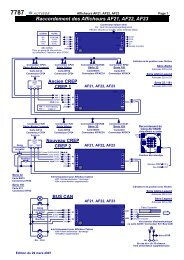
ALPHA LEGEND Installation manual page 19Towards power supply.transformerov l8VTem eratureson&Motor curr<strong>en</strong>tmeasuring deviceVECI 2Serial linkconnector(Ex : Parameter1diagnostic toolLift controllerconnectorTo AC12 boardJ8 connectorovMANCAACABFrom connectorK28 (AC1 2)VENT lCOM3 1FRRovy4F++24 W M A N l +24MAN lNSl OV CAABoII-CCSCBICCL OV CA1
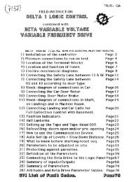
ALPHA LEGEND Installation manual narie 71PROTECTIONSA-250V dim: 5 x 20 TlME LAGFU2, FU3SIGNAL POWER SUPPLY DC CURRENTPROTECTION PROTECTION2A-250 V dim: 5 X 20 TlME LAG (brake, retirin rampelectrovagves j250V dim: 5 X 20TlME LAGFor type 1 or 2transformerTI=5A 1 T2= 2AFUIELECTRONICDRIVE MODEL.FUIEQUIPMENTPOWER SUPPLYPROTECTIONSA-250 V dim: 5 X 20 TlME LAGof the V F Model FU4SAFETY LANEPOWER SUPPLYPROTECTION 1,6A - 250V dim: QUlCK ACTING2A-250 V dim: 5 X 20 TlME LAGfor FUI & FU7FU8 for FU2 & FU3 rfType 1 transformer24R 124s POWER SUPPLY 5A-250V dim: 5x20 TlME LAGBRAKE CONTACTOR PROTECTION2A-250 V dim: 5 X 20 TlME LAGPOWER CONTACTORS3 PHASE NETWORKCURRENT FILTER380 V dim: 6 X 32RED LEDELECTRONICRECTlFlEDCURRENTPRESENT(MAIN BOARD)LI P-L2PCONTROLLERPHASES SP&,& EUSEPROTECTION for FU4 & FU84A380V dim: 8,s x 31,s for FU2 & FU3 8Type 2 transformer L1 PA-L2PA-L3PAL3P ZA-250V dim: 5x20 TlME LAG DOOR 1 & DOOR 2PROTECTION OF PROTECTIONTHE PHASE Nr3 OF THE INPUT PHASESIN CASE OF OPTIONPHASE CONTROL2A-380V dim: 8,5 x 31,sOSA-250 V dim: 5 X 20 QUlCK ACTINGONLY USE PROTISTORS~CAPABLE OF WHITHSTANDING ~OOVAND SPECIALLY CONCEIVED TO PROTECT SEMI-CONDUCTORS.THE USE OF OTHER FUSES IS DANGEROUS AND COULD DAMAGETHE TRANSISTORS IF THERE IS A POWER SURGE OR SHORT CIRCUIT.1MODEL 1 PROTISTOR@ 1
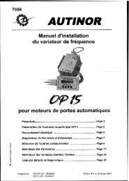
ALPHA LEGEND Installation manual page 22--Controller in Machine Room 1 Print AC12 1GMr RappelI.INot usedS 21 33 PHASES SUPPLY, Input voltage, 400 VL ? TtINCREMENTAL ENCODERs-1 HENGSTLER+24 RED RED 10 to 30 VCCOV BLUE BLACK O VCC-WHITE CHANNEL ACut the wires whlch are not used.Scre<strong>en</strong>in cable do not connect.CA1 and ~ ~Qare direction dep<strong>en</strong>dantand may have to be swapped.A1VECOl onlncrem<strong>en</strong>tal V.F Drive 1<strong>en</strong>coderr-cb",%%flBridgeif not usedSafetythermo-contact "OPTION1 Emerg<strong>en</strong>cy electrical operation )- KT1 - 'LIP L2PPrintBG22MotorThermostatElectromechanical rail 1 FKT;lgv~1 Electromechanical rail1 1
1 ^cCAR PRlORlTY KEYWOR RE-OPEN BUTTONDCOR CLOSE W O N
QCAR PRlORlTY KEYOUT OFSERVICE SWlTCHWOR REOPEN BUTTONDOOR CLOGE BVrrON
CAR PRlORlTY KEYOOUT OFSERVICE SWlTCH 0DOOR REOPW BWON8 DGOR CLOSE WiTON
fWARNINGThe proximity switches (1.L.S)must be placedat least at 20 cmof a magnetic source!The LEDs CA and CBswitch offin pres<strong>en</strong>ce ofthe magnetic stripsproximity switches (1.L.S)must be closedin pres<strong>en</strong>ce ofthe magnetic stripsConnection of proximity switches and extreme contacts
The tape head must be placedat least at 20 cmof a source magnetic !CAA 1 r 'vup contactConnection of tape head 003-1 or 003-2
V> OLIT OFY- z-4-1 SERVICE SWITEH 01 221 a.IRE SERVICE S.WlTcH 0
7m- U> OUT OF0; z::Y- :-
m- fn fn OUT OF8: $2. SERVICE SWITCH 0T-l g,;IFlRESERVICE SWITCH O
ALPHA LEGEND Installation manual page 312 SPEEDSMAGNETIC STRIP = 75 mmMAGNETIC STRIPHIGHESTLEVEL LSLOW SPEEDEMSLOW SPEED DOWNMAGNETIC STRIPDOWN STOPMAGNETIC STRIP" I--1SLOW SPEEDDOWN LEVELLINGZONELEVEL L-1ovPROXlMlTYSWITCHES (1.L.S)UP STOPMAGNETIC STRIPSLOW SPEED UPMAGNETIC STRIP1 SLOW ---. SPEED - ---UP LEVELLINGSLOW SPEED DOWNMAGNETIC STRIP1DOWN STOPMAGNETIC STRIPUP STOPMAGNETIC S'TRIPSLOW SPEED UPMAGNETIC STRIPSLOW SPEEDDOWN LEVELLINGZONELEVEL 1SLOW SPEEDUP LEVELLINGZONESLOW SPEEDDOWN STOPMAGNETIC STRIPPROXlMlTY 9 4 LEVELOSWITCHES (1.L.S) -+mx=IRE-LEVELLINGMAGNETIC STRIPl
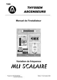
ALPHA LEGEND Installation manual page 32LEGENDAUTREGONG(') 4 USlb14 US2b 2GONG ECREP 4 EIS3b 3, VSU EVSUNSU 4 ~ ~ 1 4 bOVb 2(*) Gong 24RD b 3(Pour un gong de réouverturesur prés<strong>en</strong>ce, l'associer avec POSX).Ex: parameterldiagnostic communicationtool, VEC03, VEC30 or VisuPC (with unit 5383).A A AK26 connector K23lK26 connector KC27 connectorCANHCANL24RovMASSEK26 connectorAloha series Aloha Lea<strong>en</strong>d series 32 series 191 seriesPrint BH12 Print AC12 Print BG15 Print NI0CP24 connector CP24 connector KPIKC24 Connector KPlKC4 ConnectorFor example -CREPAF21, AF23Position indicators with arrows<strong>Alpha</strong> seriesAddresses 028 to 033<strong>Alpha</strong> Lea<strong>en</strong>d seriesAddresses 020 to 03732 1191 seriesAddresses 028 to 037GONG*+EISl b 1POSX - - WEIS2b 2 KIECREP-4 US3 b 3 34EVSUNSU + ElS4 b 1 KB2 24OV b 2 Kz 124RB 332 series-Only for indicator in carPrint BG15E/Sl = lnpui VSUKP23 Connector * ~ 1.~4191 seriesPrint NI1= output vsu AF22 Wirin ofDisplay size : 50 x 112 mmAUTINO~ gongBUS CANAF21, AF23Position indicaton with arrows<strong>Alpha</strong> Leq<strong>en</strong>d seriesAddresses 028 to 033Lea<strong>en</strong>d seriesAddresses 020 to 05FKB1 2 b CANH1 b CANL 73b24~: ->2, ovKB2 1 b MASSE CHASSISTo electromecanichal terminal railor AC09 board / K2 connecfor/ Bus CAN**VSU : only for indicator in carAF22Display size : 50 x 112 mm
Particular Display onAF21. AF22. AF23Example:EControler CREP CodeFExample:
ALPHA LEGEND Installation manual page 34
ALPHA LEGEND Installation manual page 35COMMISSIONINGPROCEDURE
ALPHA LEGEND Installation manual page 37BEFORE STARTING:This levelling adjustm<strong>en</strong>t is done in INSPECTION (INS) mode and notin MAN. For this connect the inspection wire coming -from the car roof toINS, and bridge MAN and OV.Do not put the magnets on the tape, but take them with you, as well as this installationmanual.This automatic relevelling procedure allows you to measure and register directly in thecontroller the landing heights of each corresponding floor. Each level corresponds to analtitude on the slotted tape.The lowest level is 00 00.PROCEDURE TO FOLLOW:1) Turn the switch to INS.2) Switch the ALPHA LEGEND power off and th<strong>en</strong> on again.3) Put at 1 the bit 7 DREGLA at address OFE (VEC30) or 4FE (VisuPC), of the AC12board. To if required adapt an inspection speed slower by ajusting the parameter VI(Add 003) on the communication tool (VEC03) of the VECOI board in order to facilitatepositioning on level of the car.4) Climb ont0 the car roof and take the lift down to the lowest level. Stop exactly at thefloor level!5) Press the « STOP » button on the car roof.6) Press GM and GD at the same time for 5 seconds.You can always correct the last registered height, as long as you have not moved by morethan 20 c<strong>en</strong>timetres.7) Position the ED magnet above the 003 tape-head at a height (D) corresponding to theslow down distance required (see graph on next page).Warninq: In the case of an 003-2 tape-head, position the EM magnet to the same slow downdistance (D) required for the ED magnet, see page 46.Vn : Nominal speed in metres per second.D : Slow down distance in metresExample: If the lift speed is 1.60 mls, the graph page 38 recomm<strong>en</strong>ds a slow down distance(D) betwe<strong>en</strong> 2 m 00 and 3 m 00, in Our example: 2.50 m.
ALPHA LEGEND Installation manual ~aae 38SPEEû IN M ETRES PER SECONDFigure 1 Slow down distance D in relation to the nominal speedFigure 2 Positioning of "ED" magnet
ALPHA LEGEND Installation manual page 398) Release the STOP » button on the car roof and go up to level 1 on inspection, stoppingexactly at floor level!9) Press the STOP » button on the car roof.10)Press GM and GD at the same time for 5 seconds.The software will memorise the height corresponding to level 1.11) Repeat steps 7) to 9) until you reach the highest level.12) Come back down to the lowest level.By passing the ED magnets coming down, you automatically load the slow-down distanceused by al1 levels going up or coming down. Moreover, DREGLA programmed ataddress OFE will reset to 00 to exit the automatic level set-up procedure.13) Move the lift towards the machine room on inspection, and leave the car roof, leavingthe switch still on inspection.14) Turn the ALPHA LEGEND power off and th<strong>en</strong> back on again.If fault code 61 is shown on the communication tool VEC30,a mistake has be<strong>en</strong> made during the level set-up procedure,and the whole procedure needs to be done again ...15) If the fault code 61 does not appear, cut the safety lane.Copy down each floor heinht at addresses 100 to 15C (500 to 55C for VisuPC) in the tableon page 40, so that later on you can check the lift's stopping precision (table 1) andthe slow down distance, ZONPV, read at address ODO (table 2).16) Turn the inspection switch on the car roof to Normal.17) Return to the machine room.18) Read the chapter « What to know before starting of at full speed » page 41 beforereconnecting the safety lane. In this way you can check that the lift carries out correctlyits reset sequ<strong>en</strong>ce.
Table 1 floor heightsFLOOR HEIGHTTable 2 slow down distanceSLOW DOWN DISTANCE IN MlLLlMETRESAddressODOthousands, hundred, t<strong>en</strong>s, unitsCHECK THAT THE SLOW DOWN DISTANCE "D" CORRESPONDS TO THE HEIGHT AT WHlCH YOUHAVE POSlTlONED THE MAGNETS.
ALPHA LEGEND Installation manual page 411)To programme the slow down distance on the vectorial frequ<strong>en</strong>cy drive.a) Slow down distance including relevelling speed VO.Example: you have positioned your magnet at 2.5 m, during the level height set-up phaseand the controller shows at address ODO: 2512.1l, Reduce ,the ODO distance by 150 mm andl programme this value at address 008 on the1l frequ<strong>en</strong>cy drive.These 150 mm repres<strong>en</strong>t the distance travelledin VO and the final stopping distanceprogrammed at addresses OD2 and OD3.In Our example you should programme 2362at address 008 in the frequ<strong>en</strong>cy drive.-1 1In the controller*Address DO, Dl, Ex : 2512mmb) Slow down distance with direct approach.Segm<strong>en</strong>t 5 at address OOE must be ON.Example: you have positioned your magnet at 2.5 m, during the level height set-up phaseand the controller shows at address ODO: 2512.Programme the same value at address 008in the vector drive.1lIn the driveAddress 008, Ex : 2512mmdIn the controller4 tiAddress DO, Dl, Ex : 2512mmlIll
ALPHA LEGEND Installation manual page 422)To programme the Thermal Protection.Read the nominal curr<strong>en</strong>t writt<strong>en</strong> on the motor faceplate and copy the value at addressOOD of the drive.3)Address OOE details (Hardware Option)Segm<strong>en</strong>t 0: Intégrator.Segm<strong>en</strong>t 3: MLi.Segm<strong>en</strong>t 5: Direct approach.Segm<strong>en</strong>t 6: 65"Défault temperature.Segm<strong>en</strong>t 7: Mlift 220V.
About the controller drive:You need to know in which direction the car will go as soon asyou turn on the power! ! !Wh<strong>en</strong> using the tape and 003 tape head, the magnet which was placed at the bottomduring the automatic level set-up plays the role of the special slow-down vane and contactED.This magnet acts upon the bistable ED mounted on the 003 tape head.Wh<strong>en</strong> the contact is op<strong>en</strong>, the car is below the magnet. After power up, theALPHA LEGEND s<strong>en</strong>ds the lift up to cross the magnet which will reset the tape head.The lift will stop at the next floor where it can slow down before returning to the mainfloor. You can check that the ED contact is op<strong>en</strong> by measuring the DC voltage betwe<strong>en</strong> theOV and CAB on the CP22 connector, AC12 board, or betwe<strong>en</strong> the " - " and " b " terminals onthe 003 tape head. The voltage measured should be OV or 24V (dep<strong>en</strong>ding on whetherbeam B is brok<strong>en</strong> or not). The state of ED contact (and EM) is visualised thanks to the ledlocated on the AC12 board.Contact ED is op<strong>en</strong> wh<strong>en</strong> the DC voltagemeasured betwe<strong>en</strong> " - " and " b "is OV or 24V.Wh<strong>en</strong> the contact is closed, the car is above the magnet. After power up, theALPHA LEGEND s<strong>en</strong>ds the car down to cross the magnet which will reset the tape head.The lift will stop at the next floor where it can slow down before returning to the mainfloor. You can check that the ED contact is closed by measuring the DC voltage betwe<strong>en</strong> theOV and CAB on the CP22 connector, AC12 board, or betwe<strong>en</strong> the " - " and " b " terminals onthe 003 tape head. The voltage measured should be 6V or 18V (dep<strong>en</strong>ding on whetherbeam B is brok<strong>en</strong> or not). The state of ED contact (and EM) is visualised thanks to the ledlocated on the AC12 board.00Contact ED is close wh<strong>en</strong> the DC voltagemeasured betwe<strong>en</strong> " - " and " b "is 6V or 18V.If al1 values seem coher<strong>en</strong>t, you can carry out your first full speedtest runs by closing the safety lane.
ALPHA LEGEND Installation manual page 441. Adjustm<strong>en</strong>t of the Synchronous SpeedAt the mom<strong>en</strong>t, V2 and the synchronous speed (VSy) are ,the same value.1) Select address 114 on the frequ<strong>en</strong>cy drive communication device.2) Carry out a full speed movem<strong>en</strong>t, and read the synchronous speed displayed. Copy thisvalue into parameter Vsy, address 006.II. Automatic adjustm<strong>en</strong>t of the up stopping precisionThis procedure only works in the case of a slow down distance including the relevellingspeed VO.1) S<strong>en</strong>d the lift to the lowest level.2) Program REGMO at address OFE on the communication tool VEC30 of the AC12 board.Warninq: OFE will display followed by REGMO.3) S<strong>en</strong>d the car up to the half stroke on normal.Wh<strong>en</strong> the car stops, the bit REGMO programmed at OFE will reset to 00 to exit the automaticadjustm<strong>en</strong>t procedure.Warning: The lift may perhaps not be exactly at floor level !This is normal ... it will be at floor level after the next journey.III.Automatic adjustm<strong>en</strong>t of the down stopping precisionThis procedure only works in the case of a slow down distance including the relevellingspeed VO.1) S<strong>en</strong>d the lift to the highest level.2) Program REGDE at address OFE on the communication tool VEC30 of the AC12 board.Warninq: OFE will display followed by REGDE.3) S<strong>en</strong>d the car down to the half stroke on normal.Wh<strong>en</strong> the car stops, the bit REGDE programmed at OFE will reset to 00 to exit the automaticadjustm<strong>en</strong>t procedure.Warnina: The lift may perhaps not be exactly at floor level.This is normal ..., it will be at floor level after the next journey.The value of stopping precision for each level is giv<strong>en</strong> in millimetres.
ALPHA LEGEND Installation manual ~aae 45IV.Adjustm<strong>en</strong>t of the direct approach precisionAt address OOE, on the frequ<strong>en</strong>cy drive communication device, segm<strong>en</strong>t 5 should be on.1) Select address 250, and s<strong>en</strong>d the lift to the bottom floor. The tape head may show apositive value, example: 18 mm, which means that the car has stopped 18 mm abovefloor level.lncrease the value programmed at address 008 (DV2) by this 18 mm.If the lift stops after floor level, reduce the value programmed at address 008 (DV2) by these18 mm.V.Automatic adjustm<strong>en</strong>t of the hysterisis zoneThis must be done if the lowest level is not the main floor.1) Position the lift above the ED magnets.2) Program REGHYS at address OFE on the communication tool VEC30 of the AC12board.3) S<strong>en</strong>d the car up one floor and th<strong>en</strong> down one floor, so that the tape-head passes the EDmagnets in both directions.VI.Positioning of EM magnet at top floorPosition the EM magnet at the slow-down point for the top floor, this may be useful if thelift does not cross the bottom magnets very oft<strong>en</strong>.To carry out this operation, you will need the following elem<strong>en</strong>ts:An 003-2 tape-head.A pair of magnets to position as shown on page 46.1) During normal operation, wh<strong>en</strong> the lift stops exactly at the desired floor, s<strong>en</strong>d the lift upto the top floor and position the EM magnets to obtain the desired slow-down distance(the position of the EM magnets is roughly the same as that of the ED magnets).2) If afterwards wh<strong>en</strong> coming back to the top floor, the lift does not stop at floor level, movethe EM magnets to the value corresponding to the reset height.
ALPHA LEGEND Installation manual ~aae 46IUP SLOWSPEED ZONEZONARMUP STOPPING ZONE- ZDEVER1 I 1 UP DOOR UNLOCKING ZONEZONE PVUP SLOW SPEED ZONE A?-DOWN SLOWSPEED ZONEFLOOR F-1FLOOR 2ZONE PVDOWN SLOW SPEED ZONEDOWN DOOR UNLOCKING ZONEZONARDDOWN STOPPING ZONEZONARMUP STOPPING ZONEZDEVERUP DOOR UNLOCKING ZONEUP SLOWSPEED ZONE- ZONE PVI I 1 UP SLOW SPEED ZONEDOWN SLOWSPEED ZONE1 DOWN SLOW SPEED ZONEDOWN DOOR UNLOCKING ZONEBOTTOM FLOOR OZONARDDOWN STOPPING ZONE
ALPHA LEGEND Installation manual page 47AddressO00NameVODesignationSet-up speedMinvalues0,005Maxvalues02Factory values1/10 de V2FinalsValuesO01IsoRe-levelling speed0,000< VO0,020 mls002InsInspection speed0,200,600,50 m/s003VIlnt<strong>en</strong>ediary speed0,61< V20,61 mls004006V2VSYFull speedSyncl-ironous speed> VI0,00003,OO9,999C&nfs sp$cificaüOn (ml$cli<strong>en</strong>ts spe&cafion (rds)Brake starting timeVector model01 8Jreglnertia005 %O19GP maxMax Proportional Gain > 12 HzO1 501 AGP minMin Proportional Gain < 12 Hz00401 BGI maxMax integral GainO10O1CGI minMin integral GainO0101 DAFLuDAdditional starting Flux00,O A01 EGI DepStart up integral Gain005O1FGP DepStart up Proportional Gain005020T DemaStart up Voltage006 %021G StabiStabilisation GainO1 5022FTmaxMax Voltage Frequ<strong>en</strong>cy050 Hz023FMinDMin Starting Frequ<strong>en</strong>cy0,10 Hz024NCodeNo Enwder Teeth05002500500 (500 < x < 2500)026027NPoleCountryNo of motor PolesCountry Language0040064 or 6 poles(if 6 poles, NCode=75Omini)a,=,-, a* Opt parameter Detail - OPTion - Address OOE :
036DemNumber of starts(E~P~Y)O000 9999 xxxx0000038Visu1 *VISU no 1 AddressPROGRAMMATIONF912039Visu2 *VISU no 2 AddressOF THE CURVESF91003AVisu3 *VISU no 3 AddressVlSUALlSEDF90403BVisu4 *VISU no 4 AddressON COMPUTERF908040HinT<strong>en</strong>Disable of voltage controlO0I041042TestProgTransistor Test(Program 55 for test)Programme TypeO0VEC, SCA, ARB043TManController TypeNormal, 1 speed, 2 speed044McodeCode no memoryO000046CodeCode no <strong>en</strong>tryO000* You can visualise the parameters, inputs/outputs, variables as well as the function graphson a P.C., using the P313 interface board and the VlSU P.C. programme.To do this, connect the P313 set and push the 2 <strong>en</strong>d buttons of the integrated diagnostic toolVEC03. In order to make READ PARAMETERS » appear on the display.At the <strong>en</strong>d on the P.C. visualisation, push the 2 <strong>en</strong>d buttons.- _ cdl-boagl , +-,"% 1-, P3LI'.-- -'-- 8- - --IAUTINORI - -REAO PARAMETERS---- - .-1- ?e, W ,,.- -.%.=e>YdU4- 3@OC--.- ,- J,, - -SOFTWARE1 \\>il \ Yi7 \If tee diagnostic tool is integrated in the \A(<strong>VF</strong>, V'SUPC(LOCAL'it is ESSENTIAL to press the 2 <strong>en</strong>d buttons.You can visualise:The theoretical graph : ............................................... F912The real graph : .......................................................... F91 OThe capacitor voltage : ............................................... F904The effici<strong>en</strong>t motor curr<strong>en</strong>t : ....................................... F908
ALPHA LEGEND Installation manual page 49Faults displaved bv the vector drive (VECOI Board)The Vector Drive fault code stack is found at Address 28, 29, 2A, 2B, 2C, 2D, 2E, 2F,30 and 31. At Address 28 the most rec<strong>en</strong>t fault and at Address 31 the oldest recorded fault.BEFORE LEAVING THE SITE, SET THE FAULT LIST BACK TO 00.IN THIS WAY YOU CAN KEEP BETTER TRACK OF ANY BREAKDOWNS.Consequ<strong>en</strong>ce of a and b signals changing state at the same time« 10 » cut while in motion.Fault with the 003 tape head.WARNlNG :PLEASE TAKE PRECAUTIONS WHEN YOU SEND US YOUR ELECTRONIC BOARDS(USE ANTI-STATIC BAGS)