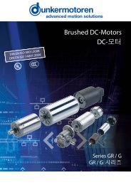
Kollektor-Gleichstrommotoren Baureihe GR/G - Dunkermotoren
Kollektor-Gleichstrommotoren Baureihe GR/G - Dunkermotoren
Kollektor-Gleichstrommotoren Baureihe GR/G - Dunkermotoren
- No tags were found...

Create successful ePaper yourself
Turn your PDF publications into a flip-book with our unique Google optimized e-Paper software.
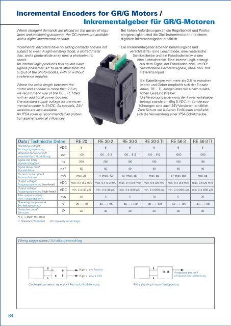
Incremental Encoders for <strong>GR</strong>/G Motors /Inkrementalgeber für <strong>GR</strong>/G-MotorenWhere stringent demands are placed on the quality of regulationand positioning accuracy, the DC-motors are availablewith a digital incremental encoder.Bei hohen Anforderungen an die Regelbarkeit und Positioniergenauigkeitsind die <strong>Gleichstrommotoren</strong> mit einemdigitalen Inkrementalgeber erhältlich.Incremental Encoders for <strong>GR</strong>/G Motors /Inkrementalgeber für <strong>GR</strong>/G-MotorenRE 20 (without cover / ohne Haube) IP 30RE 56 / RE 56 TI (without cover / ohne Haube) IP 3020±0.5Ø56±0.5Incremental encoders have no sliding contacts and are notsubject to wear. A light-emitting diode, a slotted metaldisc, and a photo-diode array form a photoelectriccircuit.An internal logic produces two square-wavesignals phased at 90° to each other from theoutput of the photo-diodes, with or withouta reference impulse.Where the cable length between themotor and encoder is more than 2.5 m,we recommend use of the RE .. TI, fittedwith an additional power booster.The standard supply voltage for the incrementalencoder is 5 VDC. As specials, 24Vversions are also available.An IP54 cover is recommended as protectionagainst external influences.Die Inkrementalgeber arbeiten berührungslos undverschleißfrei. Eine Leuchtdiode, eine metallischeSchlitzscheibe und ein Fotodiodenarray bildeneine Lichtschranke. Eine interne Logik erzeugtaus dem Signal der Fotodioden zwei um 90°verschobene Rechtecksignale, ohne bzw. mitReferenzimpuls.Bei Kabellängen von mehr als 2,5 m zwischenMotor und Geber empfiehlt sich der Einsatzeines RE .. TI, ausgerüstet mit einem zusätzlichenLeistungstreiber.Die Versorgungsspannung der Inkrementalgeberbeträgt standardmäßig 5 VDC. In Sonderausführungensind auch 24V-Versionen erhältlich.Zum Schutz vor äußeren Einflüssen empfiehltsich die Verwendung einer IP54-Schutzhaube.18.5±0.5 Ø44rotPin RE 20161 GND 0V2 -3 A4 Vcc 5V5 BRE 30 / RE 30 TI (without cover / ohne Haube) IP 30schwarz35°3041±0.5ca. 631±0.5Pin RE 56-XPin RE 56-X TI1 GND 0V1 n.c.2 I (56-3)2 Vcc 5V3 A3 GND 0V4 Vcc 5V4 n.c.5 B5 /A22.5°Pin RE 56-X TI6 A7 /B8 B9 /I (56-3)10 I (56-3)<strong>GR</strong> 63 + RE 30 / RE 30 TI (+E90) (with cover / mit Haube) IP 54Data / Technische Daten RE 20 RE 30-2 RE 30-3 RE 30-3 TI RE 56-3 RE 56-3 TIOperating voltage/Versorgungsspannung VDC 5 5 5 5 5 5Impulses per revolution/Impulszahl pro Umdrehung ppr 100 100 ... 512 100 ... 512 100 ... 512 1000 1000Signal rise time/Signalanstiegszeit ns 200 200 180 180 180 180Signal decay time/Signalabfallzeit ns* 50 50 40 40 40 40Current consumption/Stromaufnahme mA max. 25 17 (max. 40) 57 (max. 85) max. 85 57 (max. 85) max. 85Output voltage/Ausgangsspannung (low--level) VDC max. 0.4 (3.2 mA) max. 0.4 (3.2 mA) max. 0.4 (3.9 mA) max. 0.5 (20 mA) max. 0.4 (3.9 mA) max. 0.5 (20 mA)Output voltage/Ausgangsspannung (high--level) VDC min. 2.4 (40 µA) min. 2.4 (40 µA) min. 2.4 (200 µA) min. 2.4 (200 µA) min. 2.4 (200 µA) min. 2.4 (200 µA)Max. output current/max. Ausgangsstrom mA 20 5 5 70 5 70Operating temperature/Betriebstemperatur °C - 20 ... + 85 - 40 ... + 100 - 40 ... + 100 - 40 ... + 100 - 40 ... + 100 - 40 ... + 100Protection class/Schutzart IP 30 30 30 30 30 30*) C L= 25pF; R= 11kΩn Standard / Standard n On request / auf Anfrage43.51521.8±0.52.5Pin RE 30-XPin RE 30-X TI1 GND 0V1 n.c.2 I (30-3)2 Vcc 5V3 A3 GND 0V4 Vcc 5V4 n.c.5 B5 /A<strong>GR</strong> 80 + RE 30 / RE 30 TI (+E90) (with cover / mit Haube) IP 5430±0.545°Pin RE 30-X TI6 A7 /B8 B9 /I (30-3)10 I (30-3)Ø63ca. 42LIEC 130 - 9 Binder Series 723/423 8pin4pin DIN 43650Pin 30-3TI Pin 30-3TI Pin <strong>GR</strong>/E901 A 5 I 1 Motor (-)2 B 6 /A 2 Motor (+)RE 30 RE 30 + E 90 3 Vcc 5V 7 /B 3 Asto E (+)40 L 79 L4 GND 0V 8 /I 4 Asto E (-)RE 30-3 (Connection example / Beschaltungsvorschlag)ca. 35L30+5VWiring suggestions / SchaltungsvorschlagRE 30R R R2K72K72K7Ø80+154B3ABADQ-QHigh = cw. / rechtsHigh = ccw. / linksBAEX - OR4 impulses per rev /4 Impulse pro Umdrehung4pin DIN 43650Binder Typ 723 DIN 45328 8pin21IndexClockwise/counter-cw. detection / Rechts-/Links-ErkennungPulse doubling / Impuls-VerdoppelungRE 30 RE 30 + E 9055 L 77.5 LPin 30-3TI1 A2 B3 Vcc 5V4 GND 0VPin 30-3TI5 I6 /A7 /B8 /IPin <strong>GR</strong>/E901 Motor (-)2 Motor (+)3 Asto E (+)4 Asto E (-)GND84• Dimension drawings of complete drives (motor and gear) are available at www.dunkermotoren.com (Products -> direct selection)• Maßzeichnungen von kompletten Antrieben (Motor-Getriebe-Kombinationen) erhalten Sie auf unserer Homepage: www.dunkermotoren.de (Produkte -> direkte Produktauswahl)85