Kollektor-Gleichstrommotoren Baureihe GR/G - Dunkermotoren
Kollektor-Gleichstrommotoren Baureihe GR/G - Dunkermotoren
Kollektor-Gleichstrommotoren Baureihe GR/G - Dunkermotoren
- No tags were found...

You also want an ePaper? Increase the reach of your titles
YUMPU automatically turns print PDFs into web optimized ePapers that Google loves.
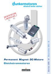
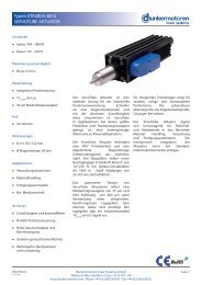
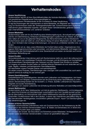
BGE 3515/6010BGE 3515/6010• External controller for DC motors from <strong>Dunkermotoren</strong>• Very compact 4-quadrant controller to controlbrush-type and brushless DC-motors (BGE 3515/6010)• Optionally as freely programmable version with integralMotion Process Unit. Allows stand-alone-operation orrepresentation of stand-alone-networks (BGE 3515/6010)• CAN interface (DSP402)• With comfortable PC-software (Drive Assistant).An attached incremental encoder RE 30-3-500 at the motoris necessary (see page 82).• The controller is protected against over-voltage,low-voltage and over-temperature cut-off• With display “ready”, “status” and “error”• The controller can be fixed by a hut-rail (35 mm) orfixing clips• Three connection plugs are included in delivery• Externe Regler für DC-Motoren von <strong>Dunkermotoren</strong>• Sehr kompakter 4-Quandranten-Regler zur Ansteuerung vonbürstenlosen oder bürstenbehafteten DC-Motoren(BGE 3515/6010)• Optional als frei programmierbare Variante mit integrierterMotion Process Unit. Diese Ausführung ermöglicht auchStand-alone-Betrieb oder die Darstellung von Stand-alone-Netzwerken (BGE 3515/6010)• Mit CAN-Schnittstelle (Geräteprofil DSP402, Protokoll DS301)• Mit komfortabler Bediensoftware (Drive Assistant).Voraussetzung ist ein angebauter Inkrementalgeber RE 30-3-500am Motor (s. S. 82).• Die Elektronik verfügt über Überspannungs-, UnterspannungsundÜbertemperaturabschaltung• Mit Anzeige “Ready”, “Status” and “Error”• Die Befestigung der Elektronik kann über eineHuttrageschiene (35 mm) oder Befestigungsklipps erfolgen• Die 3 Anschlussstecker sind im Lieferumfang enthaltenDimensions in mm / Maßzeichnung in mmFor further technical data and informationon terminal assignment, please see the operating manual atwww.dunkermotoren.com (downloads).Weitere technische Daten sowie Informationenzur Anschlussbelegung finden Sie in der Betriebsanleitung beiwww.dunkermotoren.de (downloads).Pin assignment / PinbelegungX1.1 PE earth / SchutzerdeX1.2 +U Ppower supply +10 .. +30VDC/Spannungsversorgung Leistung +10 .. +30VDCPin assignment / Pinbelegungpower supply electronic +24V/X3.1 +U 0 24V Spannungsversorgung Elektronik +24VX3.2 +AIN 0 + analog input / + analoger EingangX1.3 GND ground 0V for power supply / Masse LeistungX3.3 DIN 0 digital input 0 / digitaler Eingang 0X1.4 Ma motor phase A / Motoranschluss AX3.4 DIN 1 digital input 1 / digitaler Eingang 1X1.5 Mb motor phase B / Motoranschluss BX3.5 DIN 2 digital input 2 / digitaler Eingang 2X1.6 Mc motor phase C / Motoranschluss CX3.6 DIN 3 digital input 3 / digitaler Eingang 3X2.1 H1 hall sensor 1 / Hallsensorsignal 1X3.7 GNDground 0V for power supply electronic/Masse ElektronikData / Technische Daten BGE 3515 BGE 6010external / externexternal / externMaster functionality (MPU integrated)/Masterfunktionalität (MPU integriert)yes / jayes / jaNominal voltage electronic supply/Versorgungsspannung Elektronik VDC 10 ... 30 10 ... 30Nominal voltage power supply/Versorgungsspannung Leistung VDC 10 ... 30 10 ... 60Current consumption/Stromaufnahme mA typ. 40 @ 24V typ. 40 @ 24VPeak output current/Maximaler Ausgangsstrom A 15 15Continuous output current/Zulässiger Dauerausgangsstrom A 14 9Digital input/Digitale Eingänge 4 4Digital output/Digitale Ausgänge 1 1Analog input/Analoge Eingänge 1 (0 ... +10V) 1 (0 ... +10V)Protection class/Schutzart IP 20 20Ambient temperature/Umgebungstemperatur °C 0 ... +70 0 ... +70Rel. humidity/Umgebungsfeuchtigkeit % 20 ... 80 20 ... 80Weight/Gewicht kg 0.11 0.11X2.2 H2 hall sensor 2 / Hallsensorsignal 2X2.3 H3 hall sensor 3 / Hallsensorsignal 3X2.4 A inc. encoder channel A / Inc. Encoder-Spur AX2.5 B inc. encoder channel B / Inc. Encoder-Spur BX2.6 INX inc. encoder index channel / Inc. Encoder-Indexpower supply hall/encoder +5V/X2.7 +U 5V Spannungsversorgung für Hall/Enc +5Vhall sensor 1 inverted/X2.8 /H1 Negiertes Hallsensorsignal 1hall sensor 2 inverted/X2.9 /H2 Negiertes Hallsensorsignal 2hall sensor 3 inverted/X2.10 /H3 Negiertes Hallsensorsignal 3Iinc. encoder channel A inverted/X2.11 /A Inc- Encoder - Negierte Spur AIinc. encoder channel B inverted/X2.12 /B Inc- Encoder - Negierte Spur Binc. encoder index channel inverted/X2.13 /INX Inc- Encoder - Negierter Indexground 0V for power supply hall/encoder/X2.14 GND Masse für Hall/EncX3.8 -AIN 0 - analog input / - analoger EingangX3.9 DOUT 0 digital output 0 / digitaler Ausgang 0X3.10 CAN_HI CAN high / CAN HighX3.11 CAN_LO CAN low / CAN LowX3.12 CAN_GND CAN ground / CAN Masse9091