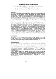
THE YEAR-BOOK OF THE COKE OVEN - Coke Oven Managers ...
THE YEAR-BOOK OF THE COKE OVEN - Coke Oven Managers ...
THE YEAR-BOOK OF THE COKE OVEN - Coke Oven Managers ...

Create successful ePaper yourself
Turn your PDF publications into a flip-book with our unique Google optimized e-Paper software.
Main types of refractory repairThe main types of refractory repair at SBCO are:• Sole flooding• Patch and peel• Quoin repairs• Firebrick Patch• Ceramic Welding• End wall rebuild• Throughwall & Regenerator repairsSome of the above repairs you may be aware of, possibly under differentnames, some you may have seen or taken part in; each though has itsown purpose, but ultimately major rebuilds will be required.Sole floodingSoles wear especially from the middle of the oven to the coke side as allthe coke mass passes over it. Powders containing aggregates are mixedto a watery suspension and layer on layer is applied; Sol is used atSBCO. Time must be given for the aggregate to set in between layers.This process is necessary though as pushing difficulties can be evidentand, if excessive wear is present, there may be a danger of the ram shoepushing the frame out.Many methods of flooding soles have been tried and reaching the centreis difficult while still keeping the mix in suspension. We’ve adopted apractice of mixing and throwing from a bucket; this is not ideal butsimple. This sometimes gets an oven pushing easier as long as it isdone correctly, i.e. adequate time is allowed between layers.Patch and PeelThis is a quick technique, which will keep an oven in service for a fewcycles. Invariably a bigger repair is required, but this technique buys timeto plan a more permanent repair. This technique is suitable for smallholes that are forming. A lump of darb is applied by a ‘spatula’ andpressed into the repair area, then smoothed over, a bit like applyingPolycell.2
Ceramic WeldingThis technique is a lifeline to coke makers with deteriorating batteries,and provides a good repair with a long life. If left too late extensivewelding will be an ongoing requirement for the rest of the battery’s life aseach repair will eventually fail due to the differential expansion betweenthe weld and the parent brick and the next repair needs to be deeper.However, if used in the early stages of spalling, this technique willensure brickwork life is lengthened considerably, for example Redcar<strong>Coke</strong> <strong>Oven</strong>’s brickwork could survive much longer if the small areas ofspalling now arising are welded now. If left until the brickwork is in poorcondition then it will be a long road just to keep chambers in service.However it may forestall rebuilds allowing for more effective planning ofmajor silica repairs. Ceramic welding is not cheap but judging by SBCO’sexperience this method is certainly well worth its weight in gold.The ceramic welding process1. Preparation – The brickwork is scrabbled until good brickwork isfound.2. Ceramic Powder - The powder is graded to similar chemical andphysical properties of the refractory to be adhered to.Fig 1: Silica welding from a platform – note insulation pads to retain heat4
3. Conveying – The powder is mixed in a vessel with compressed airand oxygen and transported through a lance to the repair area,which needs to be at a minimum 800 o C. The lance is usuallysupported on a roller and to reach further into the oven sometimes aframe is hung from the charge hole to support the lance (at thatstage normally a water cooled lance). (Figs 1 and 2.)Fig. 2: Silica welding lance support on roller. Reaction at lance head aspowder and oxygen are ‘ignited’4. Exothermic reaction – The powder ignites when it comes into contactwith the hot surface and the exothermic reaction raises thetemperature to around 2,000 o C.5. Fluxing – The temperature is sufficient to flux the material and fuseto the partially melted substrate (host refractory). The ceramic weldis deposited until a correct profile is achieved. (Fig 3) For largerholes, zero expansion ceramic tiles are inserted with the weld builtaround. In addition to walls, chamber roofs can be repaired.5
Fig 3: Finished wall – note quoin end needs a peelEnd wall rebuildUltimately the condition of a wall deteriorates to such an extent that noneof the above repair techniques is adequate to repair the brickwork and itis necessary to replace the refractory. This commences with ends of awall having to be replaced to a depth necessary to tie in to soundbrickwork. You are basically wasting your time if this is not done andonce started it is important not to disturb good brickwork. During therepair ‘rotten’ midfeathers may be found further into the oven wall thanexpected and a 6-flue repair may become an 8 or even a 10-flue repair.It follows that the next time a wall has to undergo an end repair, it isnecessary to replace further into the oven to tie-in to suitable brickwork.Consequently once started on an end wall programme, you can expectbigger repairs for years to come. In the case of South Bank, which isover 40 years old, some of the events of the past have been lost in timeand surprises occur. In some end repairs firebrick was found substitutedfor silica, and during number one oven wall end flue repair this wasfound melted.6
The end wall rebuild processFigure 4 shows a typical set up for a single end flue repair. Four ovensare left empty for this type of repair. The stoppers must be adjacent to amidfeather to prevent movement at that point. Bracing stoppers will alsobe put into the buffer ovens; this is also described below with throughwallrepairs.Fig 4: End wall Set upInsulating blankets are made on site using a suitable insulation wool,sandwiching aluminised glass cloth and held together inside a ‘cage’.Obviously these are required to ensure acceptable working conditionsbut also to protect the adjacent walls from cooling and stop prematureexpansion of the new brickwork. They are suspended through ascensionpipe and chargehole openings (fig 5).7
Fig 5: End Wall BlanketsOnce fitted, flue temperatures directly behind the curtain are controlledbetween 800 – 850 o C. Temperatures are taken on a shift basis and highor low temperatures adjusted as required. Close temperature control ofwhere the old and new flues join is critical, as should this temperature falltoo low, then a 6-flue repair may become an 8. If the temperaturebecomes too hot, new brickwork may spall when laid. The chargedovens flue temperatures are set up and operated at extended 24 hourscarbonisation times. The temperature of the remaining part of the goodwall is profiled down to prevent unwanted expansion and aid theenvironment. The end flues are then disconnected as required from thecellars area and wrecking of the end flues can commence.8
Fig 6: Roof Support techniqueRoof supports are required for a small repair, but for larger repairsgreater than six flues, roof removal is the norm. Whatever the decision,the safety of the bricklayers is paramount and as near as comfortableworking conditions possible are required. Figure 6 shows how the roof issupported. A hole is made through the top of wall and a support channellaid across the adjacent walls. A screwed rod is inserted through thesupport channel and roof and secures a bottom channel by a nut. Thenuts on the screwed rod are tightened to clamp brickwork and oncesecure you move in to next flue and repeat till the roof above the repairlength is supported. It is usual to install a sheet from it to prevent anyfalling debris from roof and shelter the bricklayers.9
Fig 7:: Roof ShelterFigure 7 shows a roof ‘shelter’ after wrecking complete. Note the shapeof the wall; there is a need to tie new brickwork into it and maintain aprofile. The chances are that this wall will have a larger repair in a fewyears’ time.Flues are wrecked from the outermost moving towards the centre of theoven. On completion of the wrecking the following procedure takesplace:1. <strong>Oven</strong> soles are repaired as required.2. The 29th course of bricks is dug out and replaced as required toestablish a firm base to rebuild the oven wall.3. Rubble is rodded from within the flues from the cellars area of thebattery.4. A camera is lowered down each flue to inspect for damage.10
5. If excessive damage is seen gas bottles are repaired from within theregenerator area.6. A dummy riser/valve is fitted from the cellars area and each flue is inturn flooded with grout to seal any cracks. After a few minutes, oncethe grout has settled and found it’s level, the valve is cracked open andthe excessive grout is then drained from the flue.7. The rebuilding of the wall then commences.Fig 8: Expansion AllowanceTo allow for expansion a slip joint of glass cloth and graphite is laid ontothe 29th course and expansion joints are packed with insulation wool,(Fig 8) After the warm up of the new wall, the expansion joints arewelded. We don’t fit expansion joints anymore as we let the wall move toits hot setting. The problem is that we are laying unexpanded bricks ontoan already expanded floor.11
Figure 9 shows that, at the roof area, firebrick is used with wool packingfor expansion. Note the poor roof condition present on this oven;nowadays we nearly always remove the roof when carrying out end fluerepairs.Fig 9: Roof Tie-inWhen the oven wall is rebuilt, a stopper is fitted where the door sits; thisstopper has an opening to allow access to the second stopper. Thetraditional practice shown in figure 10 was for the oven to be left to heatsoak for a few days, and then a hole punched through the inner stopperto accelerate warm up. The hole would be increased in size as time goeson, but this method tended to warm up the end wall inconsistently withthe top outside area being last to reach temperature. Consequently allexpansion was pushed to that point and although a trial of leavingexpansion joints was carried out, a bulge was generally always seenafterwards in the brickwork. This method was lengthy and not very goodto control but cost nothing.12
Fig 10: Traditional Warm-up PracticeNowadays hotwork burners are set up via apertures in the full-facestoppers. (Fig 11) These are clamped to the steelwork so as to preventmovement. High-pressure coke oven gas and air are ignited at theburner and the combusted gases enter the chamber via the burner athigh velocity. The oven chamber is pressurised and turbulence of the hotwaste gases takes place heating the new brickwork uniformly. Thecombustion gases are vented via the blanks fitted to the ascension pipebase rings. The flues are reconnected and ignited after four days whentemperatures within the chamber reach 800 o C.This method is carried out by specialist contractors and incurs additionalcost, but as mentioned above, the warm up is completed in four daysand is a proven technique avoiding damage due to uneven expansion. Iunderstand that this technique was originally devised by the gas boardand used for glass furnaces.13
Fig 11: High Velocity burner Warm upThroughwall & Regenerator repairsUltimately even end flue repairs are insufficient to return an oven toservice and due to extensive deterioration of the end flues, or damage atthe centre of the oven wall (or roof), or because of excessive deflectionof a wall, the only course of action left open is to replace the whole wallthroughout by a throughwall replacement. As figure 12 demonstrates,sometimes there is no choice! Invariably when conditions havedeteriorated to this extent it is the case that the regenerator region of thebattery is also in need of extensive repair although this is usuallyconfined to the outer regions.14
Since 1984 most of theoven walls have beenreplaced at SBCO includingfour walls more than once.During the interveningperiod, techniques havebeen developed to improvethe repair methods,resulting is strongerrefractory repairs than theoriginal design. In additionrepairs to the regeneratorshave been devised, asdescribed above, andmultiple wall replacementsevolved from doubles toquadruple. The remainderof this paper describesSBCO experience inthroughwall replacement.Fig 12: No Choice!The Throughwall and Regenerator Repair ProcessFor a single throughwall repair 4 ovens are left empty; for a double 5 leftempty; and for a triple 6 left empty, (i.e. no. of empty ovens = no. of walls+ 3). We have recently completed a quadruple throughwall repair; 7ovens were left empty for this repair. The buffer ovens remaining inservice are pushed and charged on 24 hours carbonisation time.When more than one wall is being replaced, strongbacks are boltedacross the buckstay of the wall to be repaired and the two adjacent walls(p/s & c/s) (Fig 13). Tie bars will be renewed, so this is done to preventoutward movement of steelwork and, as there will be no brickworkinside, therefore also preventing inward movement.15
Fig 13: Strongbacks fitted: A-pipes and elbows removedFig 14: Charger Bridge Beam16
To support the filled charge car, which weighs over 100 tonnes, travellingacross the gap due to missing walls, it is necessary to install a bridge.Figure 14 shows a double wall replacement arrangement and a bridgesupporting the running rail with ascension pipes and elbows removed atthis stage. To prevent operators driving the charge car over the bridge atexcessive speed, the slowdown of the charger is automatic (Fig 15). Thisensures less vibration and so prevents damage to the support walls anddebris falling onto the bricklayers. The slowdown needs to be well awayfrom the replacement walls to prevent sideways force on slowing.Operators hate it!Fig 15: Charger ‘Slow-Down’ Magnets visible before the BeamFigure 16 shows the rail support arrangement for a triple throughwallwith the main support beams. The position and cradle are demonstrated.17
Fig 16: Rail Support arrangement for a triple throughwall replacementTo insulate the heated walls and protect the bricklayers during therebuild, curtains are installed. The technique now used of fitting acomplete curtain rail into the oven has not only improved safety but hasreduced the time taken to complete the throughwall repairs. The rail isrolled in (Fig 17) and laid on the chamber floor and support rods lined upwith chargeholes. Slings are then dropped through the ascension pipeholes and secured to the ends of the rail. It is then raised using pull liftsand the charger davits until the support rods poke through the chargeholes. The rail is then secured at all 5 points (2 x ascension pipes and 3xcharge holes) in position.The blanket is made of 2 x 25mm supermag wool sandwiched betweenglass cloth & wire mesh, then fitted with runners. See figure 18. Once therail is in position then the blanket is hoisted up and slotted into runner. Itis then just rolled in, followed by another and so on.18
Fig 17: Rolling the curtain rail inFig 18: Cross-section of Blanket support rail and runner19
A designated person now takes crosswall temperatures on both curtainwalls; these are taken twice a day. Aim temperatures on flues are usuallybetween 800 – 850 o C but these may be altered by managementdepending on what work is being undertaken at that particular time(regenerator repairs being an example of differing aim temps).Fig 19: Doorframe supportsDoorframe supports shown in figure 19 are required and are fitted to stopthe frames falling inward. Frames could be removed if required, butleaving them in position tends to prevent quoins collapsing into thebench as the wrecking starts from top. Figure 20 shows a view fromwithin the chamber; note the charger rail support beams and also thatthe tie bars have been burnt off as the wreck proceeds, hence the needfor strongback supports.The set up for a throughwall is much the same as for end wall repairswith the exception that there is no old-new area to monitor. Chargedovens adjacent to buffer walls are on 24 hours carbonisation time andtemperatures are lowered as required on associated walls. Note the20
Fig 20: Triple throughwall during wreckingposition of insulation blankets in figures 19 and 20. Bracing stoppers arefitted to buffer ovens; these must be adjacent to a midfeather thereforepreventing movement at that point.Gas is isolated to all the flues on the wall to be wrecked. A new initiativenow being trialled at SBCO is to insert a long rod up each flue up to thesole area. Attached to the end of the rod is a 2 ¾ inch brush. The idea offitting these brushes is to minimise the effort required when clearingrubble from within the heating flues. We are now taking this trial to thenext stage whereby riser pipes will only be disconnected when required.Pipework cleaning and/or renewal continue throughout the rebuild.Figure 21 shows how the wrecking progresses from pusher side only,due to the plant machines. Note the Acrow props in position as thewrecking moves back to support the walls and blankets. When thewrecking is complete the oven soles are cleaned off. Figure 22 showsthe blankets are still in a reasonable condition and just need tidying up.21
Fig 21: Wrecking in progressFig 22: Wreck complete and blankets secured22
Blankets are lashed back at the bottom and tightened to the wall tooptimise insulation and maximise room for the bricklayers.Next, the flues are all rodded clear and an inspection of the flues iscarried out using a camera. Then work starts on the regenerators; endbottles are renewed or inserts fitted as required. Grouting is done fromthe top to fill at raft level, then flues are again rodded and pressureplates fitted. The regenerator chequers will need replacing as well ascorbels. We have used stove chequers as a substitute at SBCO due toavailability and cost. Because of the design this has resulted incombustion improvements due to larger passageways with about a 10%loss in heat recovery. Damaged corbels are replaced by arches, whichare stronger. See figures 23, 24, and 25.Fig 23: Good CorbelsFig 24: Corbel andChequer damage23
Fig 25: Corbels replaced by ArchesFigure 26 shows the dividing wall between the outer and innerregenerators is removed to access the inner regenerators, which usuallyhave better condition chequers and corbels. The inner regenerator repairwill now be progressed as required; again arches will be fitted if required,airports cleaned out and chequers replaced. Venturi ports will also becleaned out during the repair. Because wall leaks generally occur at theend of the oven wall, there is less damage through overheating to theinners.In some cases the bus flues below the regenerators are found withexcessive damage with the inner & outer dividing tiles collapsed. Thisdamage causes a restriction for the air and waste gas passage.Extensive bleeds are usually the cause of this damage. A stainless steelinsert has been designed and these are fitted as required from the cellararea of the battery. They extend to just above the bus flue area withinthe pillar wall, the total length of insert being 234 cm.Sidewall damage and leaking gas bottle flues will result in cross leakagecausing gas / air to combust in the regenerators. Before the pillar wall isremoved to expose the gas bottles, the flues are disconnected asrequired from the cellars area of the battery. The flue wall is then24
Fig 26: Regenerator dividing wall removed to access the innerregenerator. Note the corbels in the inner have been replaced by archesin the outer.Fig 27: Flue wall of Regenrator removed to reveal damaged brickwork25
emoved to reveal the brickwork needing repair as shown in figure 27. Atthis stage cracked and damaged burning bottles are also renewed asrequired. No. 62 wall was a rare case where all 7 of the coke side outergas bottles were so damaged that gas was tracking via the side of theupper bottles, located to the rear of the corbels, into the regeneratorarea. Stainless steel inserts were fitted into this region but these burntaway after approximately 2 months. These were later replaced with ahigher temperature rated stainless inserts in April 2007, and to date all ofthese flues are still burning satisfactorily. At this stage of a throughwallairports are checked and cleared if found blocked with brick.Fig 28: Completed high burner showing stainless tie-in bandsDuring the heating wall construction, a stainless steel band is used onhigh burners to prevent toppling as the wall moves on expansion asshown in figure 28. Due to the weight of the bricks it is possible to buildonly a few courses at a time due to the compression of cement before itsets. Figure 29 shows the facia plates are set by the small springs tocontrol the firebrick expansion (which is less than the silica).Thermocouples are fitted into flues 6, 13, 22 & 28 of the heating wallfrom the cellars area for the warm up. The warm up contractors then fitthree thermocouples into each oven chamber and all the thermocouples26
Fig 29: Fascia Plates and Tie bars at <strong>Oven</strong> topFig30:HighVelocityBurners inpositionarewired up to a recorder. Figure 30 shows the high velocity burners inposition. The large pipe is for air and small for coke oven gas.Combustion occurs in the burner chamber and venturi ensures hotproducts of combustion are exhausted into the oven at high velocity and27
turbulence, giving uniform heat distribution. The securing bar across theburner ensures new walls are not affected by heat impingement.Fig 31: Typical expansion curve of dense Silica brick (OCL India)Figure 31 shows the typical expansion of dense silica, which from 117 o Cis a linear expansion of 0.15% (volumetric expansion of 0.45%). Over 1.5metres this equates to 2.25 mm. Up to 165 o C expansion is relativelysmall, but at 220 – 250 o C linear expansion of 1.05% occurs when thesilica is most susceptible to spalling due to major change/volumetricexpansion of 3.15%. Over 1.5 metres, this equates to 15.75 mm. Above573 o C, linear expansion reduces to 0.45% (volumetric expansion of1.35%), which over 1.5 metres equates to 6.75 mm. The total effect ofthe above silica phase changes equates to a linear expansion of 1.65%,which is actually 1.4% because of the small amount of quartz present inthe silica. Over 1.5 metres, this would be equivalent to a change indimension of 25mm but given the minimal amount of quartz present, thisreduces to 21mm. For the length of a full wall of approximately 1528
metres, this equates to around 200mm and a 5.4m tall oven would bearound 75mm.Ambient to 150 deg C in 3 hrs150 to 180 deg C at 5 deg C/hr180 to 360 deg C at 3 deg C/hr360 to 600 deg C at 5 deg C/hr600 to 680 deg C at 8 deg C/hr680 to 850 deg C at 10deg C/hrTotal time = 8 daysFig 32: Warm up scheduleThe time taken to heat up a wall is shown in figure 32. During the heatingup it is necessary to continually adjust tie bar springs and pressure platebolts (especially during expansion stages) to allow wall to move. If thewall were not allowed to move the compression force would shatter thebricks. The pressure plate bolt shown in figure 33 is checked throughoutand always set at ¼ turn off tight. During the eight-day warming upperiod, the flues are rodded, airports checked, and waste gas cycle setup (dampers). Ignition of the heating wall burners (“strike up”) is ataround 750 o C to 800 o C. The heating wall burning conditions are checkedand when confirmed, the start-up burner is pulled out and the ovenallowed to heat soak for 24 hours at 1000 o C. The final act in the heatingup is to pull the blankets. Subsequent to the strike up, the tie barscontinually maintained at their design length as expansion still occurs.Pressure plate bolts also monitored.29
Fig 33: Pressure Plate BoltThe final actions to complete a throughwall repair are to complete theroof build, fit chargehole rings and lids, fit ascension pipes, concretequoins, reset or renew door frames, remove bracing stoppers from bufferovens, and complete any necessary remedial work to the buffer ovens.The oven re-commissioning programme comprises of the followingsteps:1. Crosswall temperature and set flue temperature profile of the walls2. Clean the soles of ovens3. Note the chamber conditions4. Decide the charging sequence of all the ovens to be returned toservice5. Bring walls to temperature6. Charge ovens7. Monitor first push and again note the chamber condition30
Closing RemarksApart from the maintenance practices I have described, there are manyother factors that come into play to determine what refractory repairsactually take place. For example, there are times when coke price is highand we need maximise production and consequently a short-term repairis the preferred business option to a more extensive long-term repair.Another factor to consider is that too many ovens out of service wouldincrease damage to battery, especially if we tried to maintain scheduleas that puts extra strain on the working ovens. So again a short-termrepair can be preferred to maintain more ovens in service.It would be probably more economic in the long term to go straight tothroughwall repairs knowing you will end up there eventually, but wenever have a bottomless pot of money, and often the repair programmeis determined by what we can afford, not what needs to be done. Leadtimes for bricks and castings means we need to plan well in advance andit is impracticable to accelerate a repair programme because of this aswe don’t carry high stocks.Finally there are the human resource issues. Nowadays there are hardlyany bricklayers left in this country, who will do hot repairs, as buildingsites pay more and offer better working conditions.Furthermore some of the work is highly specialised and few bricklayershave the knowledge and skills required. We are fortunate at SBCO inhaving a team of bricklayers who are dedicated to their work and it isthrough their efforts and everyone else associated with SBCO that wehave kept the plant operating into its fifth decade.31