OL_P1254 Model (1) - TECO-Westinghouse Motor Company
OL_P1254 Model (1) - TECO-Westinghouse Motor Company
OL_P1254 Model (1) - TECO-Westinghouse Motor Company
You also want an ePaper? Increase the reach of your titles
YUMPU automatically turns print PDFs into web optimized ePapers that Google loves.
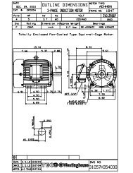
3.6.4The rotation direction of the motor will be as shown by either a nameplate on the motor or theoutline drawing. The required phase rotation of the incoming power for this motor rotation mayalso be stated. If either is unknown, the correct sequence can be determined in the followingmanner: While the motor is uncoupled from the load, start the motor and observe the direction ofrotation. Allow the motor to achieve full speed before disconnecting it from the power source.Refer to the operation section of these instructions for information concerning initial start-up. Ifresulting rotation is incorrect, it can be reversed by interchanging any two (2) incoming cables.3.6.5 Auxiliary devicesAuxiliary devices such as resistance temperature detectors, thermocouples, thermoguards, etc.,will generally terminate on terminal blocks located in the auxiliary terminal box on the motor.Other devices may terminate in their own enclosures elsewhere on the motor. Such informationcan be obtained by referring to the outline drawing. Information regarding terminal designationand the connection of auxiliary devices can be obtained from auxiliary drawings or attachednameplates.If the motor is provided with internal space heaters, the incoming voltage supplied to them mustbe exactly as shown by either a nameplate on the motor or the outline drawing for proper heateroperation.Caution must be exercised anytime contact is made with the incoming spaceheater circuit as space heater voltage is often automatically applied when themotor is shutdown.4. OPERATION4.1 Examination before start4.1.1When motors are installed in good manner, ensure the wiring is according to the diagram. Also,the following points should be noted:(a) Make sure all wiring is correct.(b) Ensure the sizes of cable wires are appropriate and all connections are well made for thecurrents they will carry.(c) Ensure all connections are properly insulated for the voltage and temperature they willexperience.(d) Ensure the capacity of fuses, switches, magnetic switches and thermo relays etc. areappropriate and the contactors are in good condition.(e) Make sure the frame and terminal box are grounded.(f) Make sure that the starting method is correct.(g) Make sure switches and starters are set at their right positions.(h) <strong>Motor</strong> heaters must be switched off when the motor is running.4.1.2 Measurement of insulation resistanceDuring and immediately after measuring, the terminals must not be touched as theymay carry residual dangerous voltages. Furthermore, if power cables areconnected, make sure that the power supplies are clearly disconnected and thereare no moving parts.12


