Service Manual Number 11 Removal Installation And Adjustments
Service Manual Number 11 Removal Installation And Adjustments
Service Manual Number 11 Removal Installation And Adjustments

You also want an ePaper? Increase the reach of your titles
YUMPU automatically turns print PDFs into web optimized ePapers that Google loves.
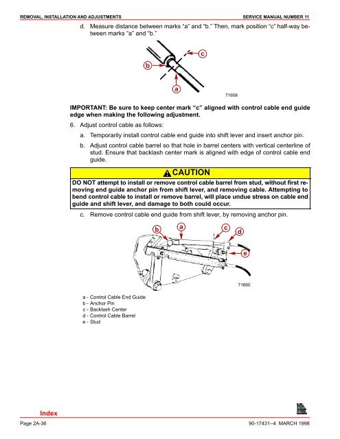
REMOVAL, INSTALLATION AND ADJUSTMENTS SERVICE MANUAL NUMBER <strong>11</strong>d. Measure distance between marks “a” and “b.” Then, mark position “c” half-way betweenmarks “a” and “b.”bca71656IMPORTANT: Be sure to keep center mark “c” aligned with control cable end guideedge when making the following adjustment.6. Adjust control cable as follows:a. Temporarily install control cable end guide into shift lever and insert anchor pin.b. Adjust control cable barrel so that hole in barrel centers with vertical centerline ofstud. Ensure that backlash center mark is aligned with edge of control cable endguide.CAUTIONDO NOT attempt to install or remove control cable barrel from stud, without first removingend guide anchor pin from shift lever, and removing cable. Attempting tobend control cable to install or remove barrel, will place undue stress on cable endguide and shift lever, and damage to both could occur.c. Remove control cable end guide from shift lever, by removing anchor pin.bacde71660a - Control Cable End Guideb - Anchor Pinc - Backlash Centerd - Control Cable Barrele - StudPage 2A-36 90-17431--4 MARCH 1998