2.3 â Electro Technical Specifications - Sør-Norge Aluminium AS
2.3 â Electro Technical Specifications - Sør-Norge Aluminium AS
2.3 â Electro Technical Specifications - Sør-Norge Aluminium AS

You also want an ePaper? Increase the reach of your titles
YUMPU automatically turns print PDFs into web optimized ePapers that Google loves.
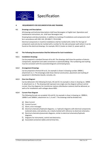
Specification4. REQUIREMENTS FOR DOCUMENTATION AND TRAINING4.1 Drawings and DescriptionsAll drawings and technical descriptions shall have Norwegian or English text. Operations andmaintenance instructions, etc. shall have Norwegian text.Drawing basis and documentation, in addition to marking of installations and components shallbe in accordance with NEK 144. (EN 60617 / EN 61346)Electrical components in machine installations shall be marked with a letter for the type ofcomponent used and also be marked with a number for the side and power path where it can befound on the electrical drawings. For example, M12.2 (motor on sheet 12, power path 2).4.2 The Following Documentation Shall Be Delivered for Each Installation:4.2.1 Installation DrawingsCan be prepared in standard formats A3 to A0. The drawings shall show the position of electriccomponents, equipment and cable connections in plants/buildings. The numbering and markingmust be consistent with the associated diagrams and drawing basis.4.2.2 Arrangement DrawingsCan be prepared in format A4 to A1. An example is shown in drawing number 18908-2,attachment no. 3. The drawing(s) shall show internal construction, placement and marking ofequipment in distribution boards, consoles, etc.4.<strong>2.3</strong> One-Line DiagramCan be delivered in the following formats; A4 and A3. An example is show in drawing no. 18908-3, attachment no. 4. The drawing shall represent one single one-line diagram without controlcurrent. One-line diagrams for transformer stations (distribution stations) shall be delivered, aswell as for installations with voltages above 400V.4.2.4 Current Flow DiagramThe following formats are accepted: A4 and A3. An example is show in drawing no. 18908-4,18908-5 and 18908-6, attachment no. 5, 6 and 7. The drawings shall be divided into:a) Main Currentb) Control Currentc) Alarm, error messagesd) Electrical schematics/hydraulic diagrams, i.e. hydraulic diagrams with electrical components(solenoid valves, end switches, etc.) clearly marked with reference to electrical schematics.e) Electrical schematics/pneumatic diagrams, similar to electrical schematics/hydraulicdiagrams.f) Diagrams for instruments, control and electronics.g) Associated connection tables and terminal lists.<strong>2.3</strong> <strong>Electro</strong> technical specification rev 8.2.doc Side 13 av 24