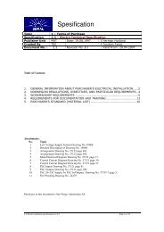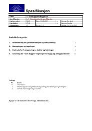
2.3 â Electro Technical Specifications - Sør-Norge Aluminium AS
2.3 â Electro Technical Specifications - Sør-Norge Aluminium AS
2.3 â Electro Technical Specifications - Sør-Norge Aluminium AS

You also want an ePaper? Increase the reach of your titles
YUMPU automatically turns print PDFs into web optimized ePapers that Google loves.
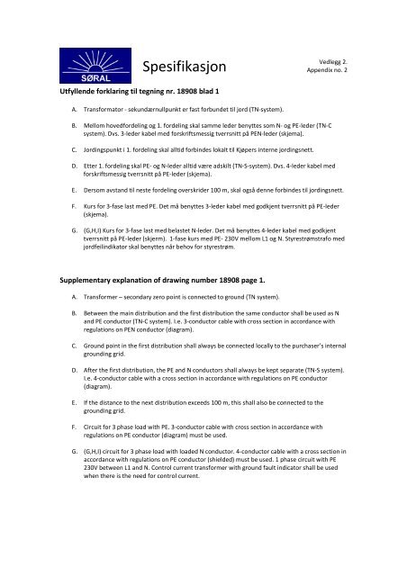
SpesifikasjonVedlegg 2.Appendix no. 2Utfyllende forklaring til tegning nr. 18908 blad 1A. Transformator - sekundærnullpunkt er fast forbundet til jord (TN-system).B. Mellom hovedfordeling og 1. fordeling skal samme leder benyttes som N- og PE-leder (TN-Csystem). Dvs. 3-leder kabel med forskriftsmessig tverrsnitt på PEN-leder (skjema).C. Jordingspunkt i 1. fordeling skal alltid forbindes lokalt til Kjøpers interne jordingsnett.D. Etter 1. fordeling skal PE- og N-leder alltid være adskilt (TN-S-system). Dvs. 4-leder kabel medforskriftsmessig tverrsnitt på PE-leder (skjema).E. Dersom avstand til neste fordeling overskrider 100 m, skal også denne forbindes til jordingsnett.F. Kurs for 3-fase last med PE. Det må benyttes 3-leder kabel med godkjent tverrsnitt på PE-leder(skjema).G. (G,H,I) Kurs for 3-fase last med belastet N-leder. Det må benyttes 4-leder kabel med godkjenttverrsnitt på PE-leder (skjerm). 1-fase kurs med PE- 230V mellom L1 og N. Styrestrømstrafo medjordfeilindikator skal benyttes når behov for styrestrøm.Supplementary explanation of drawing number 18908 page 1.A. Transformer – secondary zero point is connected to ground (TN system).B. Between the main distribution and the first distribution the same conductor shall be used as Nand PE conductor (TN-C system). I.e. 3-conductor cable with cross section in accordance withregulations on PEN conductor (diagram).C. Ground point in the first distribution shall always be connected locally to the purchaser’s internalgrounding grid.D. After the first distribution, the PE and N conductors shall always be kept separate (TN-S system).I.e. 4-conductor cable with a cross section in accordance with regulations on PE conductor(diagram).E. If the distance to the next distribution exceeds 100 m, this shall also be connected to thegrounding grid.F. Circuit for 3 phase load with PE. 3-conductor cable with cross section in accordance withregulations on PE conductor (diagram) must be used.G. (G,H,I) circuit for 3 phase load with loaded N conductor. 4-conductor cable with a cross section inaccordance with regulations on PE conductor (shielded) must be used. 1 phase circuit with PE230V between L1 and N. Control current transformer with ground fault indicator shall be usedwhen there is the need for control current.