Comprehensive System Identification of Ducted Fan UAVs - Cal Poly
Comprehensive System Identification of Ducted Fan UAVs - Cal Poly
Comprehensive System Identification of Ducted Fan UAVs - Cal Poly
You also want an ePaper? Increase the reach of your titles
YUMPU automatically turns print PDFs into web optimized ePapers that Google loves.
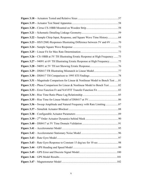
Figure 3.18 – Actuators Tested and Relative Sizes ..........................................................57Figure 3.19 – Actuator Test Stand Apparatus...................................................................58Figure 3.20 – Cirrus CS-10BB Mounted on Wooden Strip..............................................58Figure 3.21 – Schematic Detailing Linkage Geometry.....................................................59Figure 3.22 – Sample Chirp Input, Response, and Square Wave Time History...............64Figure 3.23 – HS512MG Responses Illustrating Difference between 5V and 6V ...........70Figure 3.24 – Sample Square Wave Response .................................................................72Figure 3.25 – Linear Fit for Max Rate Determination......................................................73Figure 3.26 – CS-10BB at 5V TH Illustrating Erratic Response at High Frequency.......75Figure 3.27 – 94091 at 6V TH Illustrating Erratic Response at High Frequency.............75Figure 3.28 – 94091 at 5V TH not Showing Erratic Response.........................................76Figure 3.29 – DS8417 FR Illustrating Mismatch in Linear Model...................................77Figure 3.30 – DS8417 TH Comparison to 1995 STI Findings .........................................78Figure 3.31 – Magnitude Comparison for Linear & Nonlinear Model to Bench Test .....81Figure 3.32 – Phase Comparison for Linear & Nonlinear Model to Bench Test .............82Figure 3.33 – Error Function Fr and NAVFIT Transfer Function Fit ..............................83Figure 3.34 – Rise Time Ratio Phase Lag Relationship ...................................................85Figure 3.35 – Rise Time for Linear Model <strong>of</strong> DS8417 at 5V...........................................86Figure 3.36 – Sweep Amplitude and Natural Frequency with Rate Limiting ..................87Figure 3.37 – Simulink Actuator Blockset .......................................................................88Figure 3.38 – Configurable Actuator Parameters .............................................................89Figure 3.39 – 2 nd Order Actuator Dynamics behind Mask ...............................................90Figure 3.40 – DS8417 at 5V Time Domain Validation ....................................................91Figure 3.41 – Accelerometer Model .................................................................................95Figure 3.42 – Accelerometer Stationary Noise Model .....................................................96Figure 3.43 – Rate Gyro Model ........................................................................................97Figure 3.43 – Rate Gyro Response to Constant 15 deg/sec for 10 sec .............................98Figure 3.44 – GPS Heading and Speed Model .................................................................99Figure 3.45 – GPS Error and Discrete Signal Model......................................................100Figure 3.46 – GPS Model Results...................................................................................101Figure 3.47 – Magnetometer Model ...............................................................................102x


