

Vendetta Final Proposal Part 2 - Cal Poly
Vendetta Final Proposal Part 2 - Cal Poly
Vendetta Final Proposal Part 2 - Cal Poly

Create successful ePaper yourself
Turn your PDF publications into a flip-book with our unique Google optimized e-Paper software.
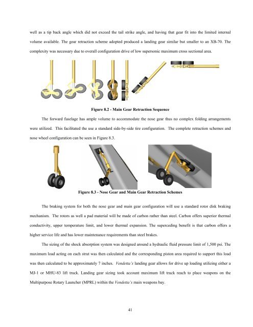
well as a tip back angle which did not exceed the tail strike angle, and having that gear fit into the limited internal<br />
volume available. The gear retraction scheme adopted produced a landing gear similar but smaller to an XB-70. The<br />
complexity was necessary due to overall configuration drive of low supersonic maximum cross sectional area.<br />
Figure 8.2 - Main Gear Retraction Sequence<br />
The forward fuselage has ample volume to accommodate the nose gear thus no complex folding arrangements<br />
were utilized. This facilitated the use a standard side-by-side tire configuration. The complete retraction schemes and<br />
nose wheel configuration can be seen in Figure 8.3.<br />
Figure 8.3 - Nose Gear and Main Gear Retraction Schemes<br />
The braking system for both the nose gear and main gear configuration will use a standard rotor disk braking<br />
mechanism. The rotors as well a pad material will be made of carbon rather than steel. Carbon offers superior thermal<br />
conductivity, upper temperature limit, and lower thermal expansion. The superceding benefit is that carbon offers a<br />
higher service life and has lower maintenance requirements than steel brakes.<br />
The sizing of the shock absorption system was designed around a hydraulic fluid pressure limit of 1,500 psi. The<br />
maximum load acting on each strut was then calculated and the corresponding piston area required to support this load<br />
was then calculated to be approximately 7 inches. <strong>Vendetta</strong>’s landing gear allows for drive up loading utilizing either a<br />
MJ-1 or MHU-83 lift truck. Landing gear sizing took account maximum lift truck reach to place weapons on the<br />
Multipurpose Rotary Launcher (MPRL) within the <strong>Vendetta</strong>’s main weapons bay.<br />
41
9 Weight & Balance<br />
Weight and balance has proven to be a challenge in designing the <strong>Vendetta</strong> for both subsonic and supersonic<br />
flight conditions. After having sized the aircraft using a weight fraction method, and after having developed an initial<br />
configuration, the next step was to develop a more accurate, class II weight buildup of the aircraft. The class II method<br />
used in the design of the <strong>Vendetta</strong> was developed from those methods found in the Nicolai, Raymer, and Roskam texts in<br />
order to obtain a collaborative and unbiased perspective. These methods involved defining several physical and<br />
geometric parameters of the aircraft. These parameters were inputs into a series of equations developed from historical<br />
weight trends. The weight estimations for various components as well as the level of agreement between authors are<br />
shown below in Table 9.I.<br />
Table 9.I - Initial Component Weight Buildup<br />
Weight (lb)<br />
Accuracy<br />
Component Roskam Nicolai Raymer Average Roskam Nicolai Raymer<br />
Structures<br />
Wing Group 9,687 11,466 7,870 9,674 0% -31% 26%<br />
Horizontal Tail 1,135 1,694 958 1,262 14% -62% 32%<br />
Vertical Tail 801 1,538 1,497 1,279 47% -34% -28%<br />
Fuselage 10,681 16,031 10,398 12,370 19% -52% 22%<br />
Main Landing Gear 2,742 2,969 1,156 2,289 -33% -52% 60%<br />
Nose Landing Gear 387 405 408 400 5% -2% -3%<br />
Propulsions 10,636 10,878 11,199 11,209 4% 0% -4%<br />
Systems 18,649 14,506 14,350 20,574 -29% 12% 13%<br />
Payload 9,280 9,280 9,280 9,280 0% 0% 0%<br />
Fuel 58,974 58,974 58,974 58,974 0% 0% 0%<br />
TOGW 123,433 128,215 128,215 127,778 4% -2% -2%<br />
The detailed weight buildup of the structures, control surfaces, systems, payload, and fuel groups has been<br />
compacted in order to save space and can be viewed in its entirety in Foldout 1. The table indicates that all three authors<br />
tend to disagree to some extent in their weight estimates of certain components, and for other components, one author<br />
may have no way of estimating that components weight at all. A more accurate and detailed component weight buildup<br />
was developed by considering all three methods and taking the average shared between them. One author’s estimation<br />
was discarded if it did not agree to within ±30% of the average of the other authors’ estimations. The remaining weights<br />
were averaged in order to develop a weight buildup for the entire aircraft. The class II weight buildup for the <strong>Vendetta</strong><br />
after the elimination process is shown in Table 9.II<br />
42
Table 9.II - <strong>Final</strong> Component Weight Buildup<br />
Weight (lb)<br />
Component Roskam Nicolai Raymer Average<br />
Structures<br />
Wing Group 9,687 XXXXXX 7,870 8,779<br />
Horizontal Tail 1,135 1,694 958 1,262<br />
Vertical Tail 801 1,538 1,497 1,279<br />
Fuselage 10,681 XXXXXX 10,398 10,540<br />
Main Landing Gear 2,742 2,969 1,156 2,289<br />
Nose Landing Gear 387 405 408 400<br />
Propulsions 11,098 11,352 11,662 11,675<br />
Systems 18,649 14,506 14,350 20,574<br />
Payload 9,280 9,280 9,280 9,280<br />
Fuel 58,974 58,974 58,974 58,974<br />
TOGW 125,051<br />
Inertias were calculated using guidelines outlined by the Society of Allied Weight Engineers (SAWE). Each<br />
component mass and location in reference to the aircraft center-of-gravity was used to calculate that components inertia.<br />
The sums of these inertias were then used to calculate the total moments<br />
of inertia about the <strong>Vendetta</strong>’s principal axes shown in Figure 9.1. In<br />
order to determine whether or not these values were accurate, the<br />
moments of inertia were transformed into non-dimensional radii of<br />
gyration coefficients. These coefficients were then compared to typical<br />
values for a jet bomber provided by SAWE. The inertias are shown in<br />
Table 9.IV and the non-dimensional radii of gyration coefficients as<br />
Figure 9.1- Principle Axes<br />
compared to the SAWE predicted coefficients are shown in Table 9.III.<br />
Table 9.III indicates that the inertias are well within the typical values for a jet bomber except about the roll axis.<br />
This is because the <strong>Vendetta</strong> is similar to a typical jet bomber in length; however, it has a much shorter wingspan. This<br />
would constitute a smaller moment of inertia about the roll axis.<br />
After having developed an initial configuration and a more detailed class II weight buildup, the next step was to<br />
balance the aircraft. This was done for two types of payload, the first being fixed equipment and the second being nonfixed<br />
equipment, fuel, and payload.<br />
43
<strong>Vendetta</strong>’s configuration was<br />
created by placing components about<br />
a predetermined CG location. The<br />
components were arranged to create<br />
the smallest airframe possible while<br />
leaving room for the fuel and<br />
payload. The heaviest fixed<br />
equipment items were placed first<br />
Table 9.III - Inertia Estimation<br />
Inertias (slug ft 2 )<br />
Ix Iy Iz Ixy Ixz Iyz<br />
69,547 1,165,870 1,228,330 0 -6,478 0<br />
Table 9.IV – SAWE Inertia Validation<br />
Non-dimensional Radii of Gyration<br />
Rx Ry Rz<br />
<strong>Vendetta</strong> 0.16 0.35 0.46<br />
SAWE 0.31 0.33 0.47<br />
Accuracy 49% 5% 1%<br />
followed by the smaller and lighter systems. Once the aircraft balanced empty, the payload was placed. This caused a<br />
slight rearrangement of items until the aircraft balanced both empty and with the payload. This process was repeated for<br />
the fuel loadout.<br />
In order to minimize the trim drag on the aircraft, it was opted that the aircraft’s center-of-gravity location stay as<br />
close to the aerodynamic center as possible. This was a difficult task because of the dramatic shift in the location of the<br />
aerodynamic center when transitioning from subsonic to supersonic flight conditions. A trim tank was considered in<br />
order to allow the center-of-gravity to follow the aerodynamic center during this dramatic shift in order to maintain a<br />
neutrally stable condition at both subsonic and supersonic flight conditions; however, this idea was discarded because the<br />
trim tank would require additional fuel volume in an already congested aircraft. To minimize trim drag without the use<br />
of a trim tank, the aircraft would have to fly with an unstable static margin, subsonically, and with a stable static margin,<br />
supersonically until enough fuel could be consumed to trim the aircraft.<br />
A center-of-gravity monitor makes use of fuel burn control in order to keep the aircraft as close as possible to a<br />
neutrally stable flight condition. Furthermore at both TOGW and empty weight the aircraft is balanced such that it<br />
provides for a 5% unstable static margin. With an aerodynamic shift of 12%, the aircraft transition to a 7% stable static<br />
margin as it accelerates to supersonic flight. The center-of-gravity monitor then controls the fuel burn in such that the<br />
<strong>Vendetta</strong>s center-of-gravity follows the aerodynamic center and thus maintains neutral stability.<br />
A computer code was developed in order to simulate the center-of-gravity monitor. The first step in developing<br />
this code was to obtain the best solution to balance the fuel and payload throughout the mission. The code required four<br />
inputs including; the locations and weights of <strong>Vendetta</strong>’s fixed equipment, the location and weight of the fuel at any<br />
given time, the amount of fuel burned at intervals throughout the mission profile, and the desired center-of-gravity<br />
location at that interval. With these inputs, the code can then determine which tank to burn fuel from in order to obtain<br />
44
the center-of-gravity location closest to that corresponding to the desired static margin. The code then outputs the<br />
center-of-gravity location and the remaining fuel payload. This is done at 10-second intervals throughout the 5-hour<br />
mission. Using this data, the center-of-gravity path can then be plotted against corresponding to the desired static<br />
margin.<br />
The next step was to balance the weapons payload. Because the weapons payload was placed in a rotary<br />
launcher, the center-of-gravity of the payload was concentrated in one location. If it had been placed in a more<br />
conventional arrangement spread across the belly of the aircraft, the center-of-gravity of the weapons would have also<br />
been spread across the belly of the aircraft. By concentrating the center-of-gravity of the weapons payload in one<br />
location and placing the weapons payload on top of the aircraft’s empty weight center-of-gravity location, deployment of<br />
the weapons payload did not generate any problems in balancing the aircraft or in disturbing the static margin. The<br />
center-of-gravity is shown tracking along the path of the desired static margin by means of fuel monitoring and pumping<br />
in Figure 9.2.<br />
Figure 9.2 - Center-of-Gravity Excursion<br />
The figure indicates that the center-of-gravity location at takeoff gross weight is slightly aft of the neutral point;<br />
however, the center-of-gravity tracks the desired static margin shortly after the aircraft has transitioned to supercruise.<br />
Notice the path of the aerodynamic center as it shifts during the transition from subsonic to supersonic flight. It is clear<br />
that the aircraft flies supersonically shortly after takeoff, or when the aircraft’s gross weight is just below takeoff gross<br />
45
weight. Furthermore, near the zero fuel weight, the aircraft flies subsonic for the remainder of the flight. The figure also<br />
indicates that with the current fuel tank arrangement, the desired static margin cannot be tracked during the final portion<br />
of the supercruise because there is not enough fuel available to properly trim the aircraft. At this point, the center-ofgravity<br />
is influenced by only the fixed weight of the aircraft and again the aircraft remains at a 5% unstable static margin<br />
during landing. This plot indicates that the center-of-gravity monitor works together with the control system in order to<br />
minimize trim drag while at the same time maintaining the aircraft’s controllability.<br />
46
10 Stability and Control<br />
To initially size the horizontal tail, tail volume coefficients from historical aircraft were analyzed. This was done<br />
in an attempt to determine the rough size of the horizontal and vertical tail surfaces prior to addressing stability and<br />
control issues. The tail volume coefficients are unitless parameters defined by geometric values relating the size of the<br />
empennage surface to the aircraft. The horizontal and vertical tail volume coefficients are defined in the following<br />
equations.<br />
V<br />
H<br />
SHTL<br />
=<br />
c S<br />
W<br />
HT<br />
W<br />
V<br />
V<br />
SVT<br />
L<br />
=<br />
b S<br />
W<br />
VT<br />
W<br />
Because the demands for most supersonic cruising aircraft are considered similar to a certain extent, the historical<br />
values of tail volume coefficients are used to back out the planform areas for the horizontal and vertical surfaces.<br />
Similar aircraft and their tail volume coefficients are presented in Table 10.I.<br />
Table 10.I - Historical Aircraft Tail Volume Coefficients<br />
Tail Volume Coefficients<br />
Aircraft<br />
V H<br />
Boeing SST (2707-300) 0.36 0.049<br />
Concorde n/a 0.080<br />
GD F-111A 1.28 0.064<br />
Rockwell B-1B 0.80 0.039<br />
TU-22M 1.11 0.087<br />
TU-144 n/a 0.081<br />
Average 0.58 0.067<br />
Using the average tail volume coefficient for these similar aircraft yielded a horizontal stabilizer area of 386 ft 2 .<br />
This is rather large and may be attributed to the fact that these vehicles require large robustness in CG travel without the<br />
use of a flight control augmentation system (CAS). Likewise, the vertical tail would require 196 ft 2 of area. This<br />
number is driven slightly larger due to the fact that some of the larger historical tail volumes are inflated because these<br />
aircrafts’ verticals are mounted on booms which extend aft. These booms allow for greater moment arms and make the<br />
vertical more effective.<br />
The effects of horizontal tail area on longitudinal static stability were looked at in an attempt to determine what<br />
the driving factors for horizontal tail area are. A Roskam class II method was used to see how the increased weight of a<br />
bigger horizontal affects the longitudinal static margin. It became apparent that as the tail grows, the CG of the entire<br />
configuration shifts aft. This also shifts the effective neutral point (center of pressure) of the aircraft aft at a faster rate<br />
than the CG shifts aft. At approximately 108 ft 2 of horizontal area the <strong>Vendetta</strong> has a neutrally stable static margin at<br />
V V<br />
47
Mach 0.3. A horizontal that is bigger than 108 ft 2 yields a stable aircraft but will pay the price in trim drag if the aircraft<br />
is too stable. This size will certainly increase due to other constraints.<br />
A stable static margin is necessary in flight without the use of a digital flight control system. The RFP mandates<br />
an unaugmented static margin between -30% and 10% as well as adherence to MIL-8785C, the military specification for<br />
handling qualities of aircraft. A statically unstable aircraft would have a tendency to pitch up in a static level condition.<br />
The purpose of the horizontal tail is to apply a force which counteracts this offending moment. This comes at the price<br />
of trim drag, however. As the elevator is deflected, drag is created and this hurts the overall aircraft performance in<br />
cruise. It is because of this drag that a neutrally stable or marginally stable (1-3%) aircraft is desired in cruise where the<br />
aircraft does not need to maneuver much.<br />
The aerodynamic center (center of pressure) on the wing and most surfaces propagates aft as the Mach number<br />
passes the transonic regime. This shift effectively leaves the difference in neutral point and center-of-gravity greater.<br />
The difference means the aircraft is actually more stable in a supersonic cruise. The fact that the center-of-gravity is so<br />
far forward in relation to the neutral point causes the aircraft to pitch down. More trim is required which causes more<br />
drag. This phenomenon is known as Mach tuck. It is because of this that the weight and balance of the aircraft must be<br />
closely in synch with the control system. Trim drag will be minimized and controllability will be enhanced with<br />
completely integrated systems.<br />
The trim drag created could be avoided by shifting the CG, by altering the neutral point, or designing the aircraft<br />
to be unstable subsonic and stable supersonic. The use of a trim tank was investigated to pump fuel aft and shift the CG<br />
closer to the neutral point in supersonic cruise. This notion was dismissed because the tank would be a waste of space<br />
and would complicate ground procedures where refueling would have to leave the tank partially empty. A canard could<br />
be used to destabilize the aircraft by moving the neutral point forward and closer to the CG but it would make the<br />
<strong>Vendetta</strong> less controllable in the subsonic landing and takeoff conditions. This extra control surface would add to the<br />
cost and complexity. A fuel management system could be used to burn fuel from certain tanks to keep the CG travel in<br />
check. After analyzing the abrupt shift in the neutral point when the <strong>Vendetta</strong> climbs to its cruise condition, it was<br />
decided that the fuel management system could not pump fuel fast enough to trim the aircraft (Section 7), with the same<br />
being true when decelerating. Use of a digital flight control system (DFCS) which is provided as Government Furnished<br />
Equipment (GFE) would allow the aircraft to fly unstable subsonic. The DFCS could easily allow a 0% - 7% unstable<br />
aircraft takeoff and land. The wing was placed and the empennage sized for the <strong>Vendetta</strong> to be 5% unstable in the<br />
subsonic regime and 7% stable in the supersonic regime without CG modification due to the 12% shift. The fuel<br />
48
management system could then be used to enhance cruise performance by pumping fuel in a way which results in neutral<br />
or marginal static stability. Canting the horizontals in a V-tail configuration was investigated in an attempt to shape the<br />
empennage in a stealthy manner. The effective area of the vertical and horizontal are functions of the square of the<br />
cosine of the cant angle. These effects are reflected in Figure 10.1.<br />
Figure 10.1 - Horizontal Area Required for Static Stability with Cant Angle<br />
It can be seen from the plot that as cant angle increases, total planform area of the horizontal must increase to<br />
maintain the nominally desired static stability of 5%. Five percent was chosen because at this stage in the sizing it was<br />
uncertain what the dynamic characteristics of the aircraft would be. Attempting to maintain a minimally statically stable<br />
aircraft eases the job of control system design. Angles up to 30° were looked at because it would be unwise from an<br />
RCS point of view to approach a 90° angle created by larger cants near 45°. Beyond 45° the trend would be the same;<br />
however the horizontal would drive the area instead of the vertical.<br />
This plot shows that only 118 ft 2 of horizontal area is required to maintain the desired static margin. This is far<br />
off from the historical class I method and by initial inspection appears small. The area required maintaining static<br />
stability is not the driving factor in the size of the horizontal. Control power required to rotate the aircraft, dynamic<br />
considerations, and high angle-of-attack recovery will most likely drive this size.<br />
A similar study was conducted on the vertical stabilizer to see what area would required for varying cant angles to<br />
maintain 0.001 (1/degree) lateral weathercock stability. This is illustrated in Figure 10.2.<br />
49
Figure 10.2 - Vertical Area Required for Static Stability with Cant Angle<br />
From Figure 6.3 it can be seen that at 30°, 165 ft 2 of vertical area is required to maintain 0.001 (1/degree) of<br />
lateral weathercock stability. Although the 30° cant angle on the verticals was initially selected to match the bottom<br />
fuselage facets for RCS considerations, lowering that angle to 20° would allow other advantages. Shallower cant angles<br />
are easier to manufacture, require less structure, weigh less, and have less coupling with pitch modes. For these reasons,<br />
the impact on RCS was investigated for the 20° cant angle as well as the pitch coupling term for rudder deflection, C<br />
δ<br />
.<br />
The RCS code was run on two aircraft configurations. The same wing, fuselage, and horizontal were modeled<br />
with the vertical planforms mounted at both 20° and 30°. The results of that study are shown as Figure 10.3 for 5 GHz<br />
monostatic radar sweeping a full 360° azimuth.<br />
m r<br />
50
40<br />
30<br />
20<br />
10<br />
0<br />
-10<br />
-20<br />
-30<br />
-40<br />
-50<br />
20° Canted Vertical<br />
30° Canted Vertical<br />
Figure 10.3 - Radar Cross Section Impact of 20° vs. 30° Vertical Cant Angle<br />
Figure 10.3 clearly shows that there is an impact on the RCS for changing the cant angle. The RFP required -13<br />
dBm 2 return is shown in red for those azimuth angles it is fulfilled. As mentioned in the RCS section, this requirement is<br />
only mandated for the frontal 0° azimuth angle. Going to a 20° cant does not violate this requirement and yields the<br />
aforementioned benefits.<br />
The effective area of a rudder sized to 27% mean aerodynamic chord of the vertical was calculated in the<br />
horizontal plane of the aircraft. In normal non-canted configurations,<br />
for this coupling term and various cants.<br />
Cm<br />
δ r<br />
is nonexistent. Table 10.II shows the values<br />
Table 10.II - Pitching Moment Coupling with<br />
Rudder Deflection for Various Vertical Cant Angles<br />
Vertical Cant Angle C<br />
(165 ft 2 m r<br />
27% m.a.c. Rudder) δ<br />
0° 0.0000<br />
10° 0.0004<br />
20° 0.0009<br />
30° 0.0021<br />
The extra 10° cant resulted in a substantially larger pitch coupling term. In addition to the complications of<br />
canting more, a 30° angle would mean that a more complex mixer and control system would be required. This would<br />
add to the cost and is avoided.<br />
51
It is important to note that the previous static methods do not take into account the dynamic characteristics or<br />
modes of this aircraft. With such a large amount of the fuselage in front of the center of pressure, the <strong>Vendetta</strong> may<br />
require a complex yaw damper or larger vertical to compensate. Use of flight simulation and dynamic analysis tools are<br />
utilized for these concerns.<br />
The size of the vertical could potentially be driven by the one<br />
engine inoperative (OEI) control power requirements. Because the<br />
engine nozzle centerlines are mounted considerably offset from the<br />
centerline at 3 feet, a large yawing moment will be created if the<br />
135,000 ft-lbs<br />
<strong>Vendetta</strong> loses an engine during takeoff. The engines produce roughly<br />
45,000 pounds of thrust and would generate a 135,000 foot-pound<br />
moment. Table 10.III shows the results of the rudder control power<br />
analysis for this critical OEI condition at a takeoff speed of 1.2 times<br />
the stall speed at sea level. In this configuration the <strong>Vendetta</strong> can<br />
45,000 lbs off<br />
center<br />
maintain a 953 fpm climb at military power and 3,435 fpm at<br />
maximum afterburning thrust. This performance is overkill, but is<br />
Figure 10.4 - OEI Forces and Moments<br />
driven by the RFP requirement for zero foot per second specific excess power at a load factor of two.<br />
Table 10.III - Rudder Control Power Results for OEI Condition<br />
Parameter Notation Value<br />
Side Force due to Rudder C yδr 0.0105<br />
Rolling Moment due to Rudder C lδr 0.0072<br />
Rudder Effectiveness C nδr -0.0070<br />
OEI Critical Yawing Moment<br />
135,000 ft lb<br />
Rudder Deflection Required in OEI Condition at Takeoff 13.6°<br />
With a rudder effectiveness of -0.0070 (1/deg), a 13.6° rudder deflection is required to keep the aircraft flying<br />
straight in the OEI condition on takeoff. This is not too large, and would suffice by allowing approximately another 10°<br />
of rudder deflection for the pilot to yaw the aircraft beyond the straight condition for controllability. In this condition,<br />
the aircraft would be susceptible to large amounts of sideslip, β.<br />
This rudder deflection would be substantially higher if a higher cant angle were used. In these critical situations<br />
where the aircraft is in danger, the added drag created by the mixing is desired to be as little as possible.<br />
A separate 4-surface empennage was now made necessary because V-tail was shown to be ill-advised. If a pure<br />
v-tail was chosen, it would have to be full-flying due to the demand placed on the surface and hinge lines in supersonic<br />
52
flight. This would require a large actuator and large structural members in the aft portion of the aircraft. This would<br />
considerably drive the configuration away from initial RCS-friendly layouts as well as increasing complexity and cost.<br />
The <strong>Vendetta</strong> configuration utilizes a 20° cant on the<br />
verticals and a separate full-flying horizontal as seen in Figure<br />
10.5. It was mentioned earlier that one of the reasons the<br />
horizontal tail volume coefficient was larger in the historical<br />
aircraft was because those aircraft did not utilize control<br />
augmentation systems or digital fly-by-wire control systems.<br />
Figure 10.5 - <strong>Vendetta</strong> Empennage Configuration<br />
Not only did they have to account for wide shifts in CG, they<br />
also had to combat the muck tuck problem associated with<br />
breaking the sound barrier.<br />
Figure 10.6 shows that as the aircraft<br />
exceeds the critical Mach number, the center<br />
Mach trim<br />
of pressure of the wing and other control<br />
surfaces travels aft. In the case of the<br />
<strong>Vendetta</strong>, this leaves the CG an extra 12%<br />
m.a.c. in front of the neutral point; this<br />
makes it 12% more stable. This 12% shift<br />
mg<br />
Figure 10.6 - Mach Tuck Illustrated<br />
12% m.a.c.<br />
was calculated with the Air Force’s Data Compendium (DATCOM) methods. The <strong>Vendetta</strong> cannot maintain trimmed<br />
flight with the CG any further forward than 9% stable configuration. The aircraft would not have enough control power.<br />
The use of a fuel monitor and a DFCS will be used to control the <strong>Vendetta</strong> throughout the flight envelope.<br />
A DFCS will not impact the design too much because complex navigation and autopilot systems will already<br />
have to be incorporated into the design. In addition to this, the DCFS will be used to enhance the dynamic modes of the<br />
aircraft. This is required due to the large fore body and unstable pitch break exhibited by the <strong>Vendetta</strong>. Also, the 2010<br />
delivery date will mean that next generation control laws and hardware could be implemented. All modern advanced<br />
fighters being designed today utilize such systems. The DFCS along with the fuel management system would maintain<br />
the static and dynamic stability.<br />
DATCOM and the compiled Digital DATCOM Fortran code proved to be useful tools in calculating many of the<br />
aerodynamic stability and control derivatives for the <strong>Vendetta</strong>. This was done in an attempt to identify problematic<br />
53
ehaviors and to adhere to MIL-8785C. It was calculated that the <strong>Vendetta</strong>’s fuselage forebody will destabilize the<br />
aircraft an additional 3.1% in subsonic cruise and 5.0% in supersonic cruise. The wing was placed to account for this.<br />
This is much improved over previous configurations where the fuselage destabilized the aircraft up to 16%. This is due<br />
to the fact that so fuselage with a large mean width was in front of the CG and NP. Figure 10.7 shows the <strong>Vendetta</strong>’s<br />
pitch break characteristics in the subsonic low speed and supercruise regimes given a CG location that would yield a<br />
statically stable aircraft.<br />
-0.6<br />
Lift Coefficient (C L )<br />
-0.4<br />
UNSTABLE<br />
NEUTRAL<br />
-0.2<br />
-0.25 -0.2 -0.15 -0.1 -0.05 0 0.05 0.1 0.15 0.2 0.25<br />
0<br />
0.2<br />
M = 0.2<br />
M = 1.6<br />
0.4<br />
0.6<br />
0.8<br />
Moment Coefficient (C m )<br />
Figure 10.7 - Pitch Break Characteristics<br />
This figure shows that as the <strong>Vendetta</strong> rotates and has some angle-of-attack in the low speed subsonic (Mach 0.2)<br />
regime, it will want to continue to rotate and break away. In the supercruise, the aircraft behaves much more linearly.<br />
The subsonic characteristics are of some concern, but even simple feedback schemes in the DFCS solve this problem.<br />
The supersonic characteristics are actually more desirable because the maneuvering required is very light and the control<br />
system will not be oscillating or fluttering the control surfaces, which creates unnecessary drag, to keep the aircraft<br />
flying straight.<br />
A full state-space based model for the aircraft driven by a Taylor expansion and fit into equations of motion was<br />
developed for flight simulator validation. These forms are too complex for simple dynamic analysis, so the literal factor<br />
forms of the dynamics modes were used to determine conformity with MIL-8785C.<br />
The literal factors are nothing more than simplifications of the transfer function forms for longitudinal and lateral<br />
modes of interest. These forms omit insensitive stability derivatives. The conformity with the military specifications for<br />
handling quality is shown in Table 10.IV.<br />
54
Table 10.IV - Longitudinal and Lateral Dynamic Mode Conformity with MIL-8785C<br />
Damping ratio (ζ) Natural Frequency (ω n )<br />
Mode <strong>Vendetta</strong> MIL-8785C <strong>Vendetta</strong> MIL-8785C MIL-8785C Level<br />
Phugoid 0.094 > 0.04 0.091 - I<br />
Short Period 0.921 0.35 – 1.3 4.721 - I<br />
Dutch Roll 0.103 > 0.08 1.960 > 0.4 I<br />
Table 10.IV shows that the <strong>Vendetta</strong> satisfies all of the military specifications for these three important modes<br />
while in a subsonic cruise with the CG monitor. The only thing of concern regarding these results is high value for<br />
undamped natural frequency in the Dutch Roll mode. It is not uncommon for aircraft of this size and type to incorporate<br />
fairly simple yaw dampers operating on the yaw rate. With the use of the DFCS, the <strong>Vendetta</strong> has no problem keeping<br />
that mode in control. Because there is a large amount of robustness available with CG excursion and the DFCS, the<br />
longitudinal modes are well within the Type I military specifications and remain there in the supercruise.<br />
From inertia computations illustrated in the weights and balance section (Section 7), it became apparent that the<br />
<strong>Vendetta</strong> has a very small inertia that would need to be overcome to roll. This is due to the wings being the only<br />
significant structure located off the centerline. This makes for very favorable roll damping and allows for the flaperon<br />
and aileron configurations to be driven by the sizes required for high lift augmentation as presented in the aerodynamics<br />
section. The final sizes and parameters for the empennage and roll control are presented in Table 10.V.<br />
Table 10.V – Empennage Surfaces<br />
Surface Area (ft 2 ) Control Surface<br />
Horizontal<br />
Stabilator<br />
270.0 Full-Flying<br />
Vertical<br />
Stabilizer<br />
165.0<br />
Rudder<br />
@ 27% m.a.c.<br />
10.1 Simulation<br />
Validation of a large supersonic aircraft like <strong>Vendetta</strong> is difficult due to limitations in experimental tools.<br />
Subsonic wind tunnel models would be limited to testing takeoff and landing aerodynamics and would be inaccurate due<br />
to Reynolds number discrepancies. Because of this, flight simulation was utilized to test the design of the aircraft. The<br />
<strong>Cal</strong> <strong>Poly</strong> Flight Simulator was used to evaluate handling qualities, ground handling, up-and-away tasks, and low speed<br />
performance. The flight simulator consists of a flight cab and instrument panel as shown in Figure 10.8 and Figure 10.9.<br />
55
Figure 10.8 - Pheagle Simulator<br />
Figure 10.9 - Flight Cab and Instruments<br />
Desktop computers running a Windows operating system and two analog computers control the instrumentation,<br />
force- feedback, and control inputs. The simulation architecture is built using Simulink, though most of the<br />
computationally intensive components such as the six-degrees-of-freedom (6DOF) model are written in C++ as S-<br />
Functions. The equations of motion used in the 6DOF are based on NASA Dryden equations of motion.<br />
A non-linear aerodynamics model was created for <strong>Vendetta</strong> and implemented in the simulator using a table<br />
lookup system. This system allows aerodynamic force and moment coefficients to be looked up using a series of user<br />
defined tables. The force coefficients for each of <strong>Vendetta</strong>’s flying surfaces were defined as functions of Mach number,<br />
relative airflow angle, and control surface deflections. Moment coefficients were calculated based on the forces and<br />
moment arms of each surface. The longitudinal moment arms varied with CG and neutral point locations. Drag build up<br />
data was used to accurately model the variation of zero-lift drag coefficient with Mach number and altitude (due to<br />
Reynolds number variation). Additional fuselage force and moment contributions as well as linear dynamic stability<br />
derivatives and downwash at the horizontal tail were calculated using DATCOM and incorporated into the model. A<br />
total of 10 control surfaces were modeled in the simulation: left and right elevator, rudder, aileron, leading edge flaps,<br />
and trailing edge flaps. Center-of-gravity location and landing gear extension were also modeled using control inputs.<br />
The simulation model was built from an aerodynamic point of view to avoid building predefined stability and<br />
control performance into the simulation. For example, rather than defining a stick-fixed neutral point location for the<br />
configuration, the aerodynamic forces and moments that define the neutral point were modeled. The resulting simulation<br />
is only limited by the accuracy of the aerodynamic data. Because no experimental methods could be used to obtain data,<br />
the data is most likely inaccurate in extreme conditions such as high angles-of-attack or sideslip angles or under highly<br />
dynamic flight conditions.<br />
56
Additional components were integrated into the simulation model or modified from existing components to meet<br />
<strong>Vendetta</strong>’s exact specifications. The engine deck included in this report was integrated into the flight simulator by<br />
implementing code to lookup, uncorrect, and output the thrust and fuel flow values for the current flying condition and<br />
throttle setting. Fuel flow was integrated during the simulation to accurately model the consumption of fuel during a<br />
flight and its effect on the weight and moment of inertias of the aircraft. The landing gear model calculates the external<br />
forces produced by each landing gear leg based on its position and properties. Friction, braking, and steering are<br />
modeled allowing the ground handling qualities of <strong>Vendetta</strong> to be simulated and evaluated. Additional systems such as a<br />
thrust reverser model, crash detector, and nonlinear actuators were utilized in the simulator. The simulator uses 3DLinx,<br />
an OpenGL based graphics package as shown in Figure 10.10. It provides pilot feedback and situational awareness by<br />
modeling of terrain, runways, and other aircraft in addition to a heads-up-display (HUD) (Figure 10.11).<br />
Figure 10.10 - Graphics and Environment<br />
Figure 10.11 - Heads up Display<br />
The results of the flight simulation indicate that the unaugmented <strong>Vendetta</strong> is a difficult aircraft to fly. The<br />
aerodynamic model shows that the aircraft is statically unstable in subsonic conditions, however due to the high<br />
moments of inertia, the time to double is large enough that it can be controlled by an experienced pilot. The addition of<br />
simple pitch and yaw rate feedback greatly improved the handling qualities and reduced the workload on the pilot while<br />
the control surfaces remained unsaturated. Clearly, sophisticated outer loop controls including an altitude hold, heading<br />
hold, and a waypoint navigator would be required to complete the design mission. This result confirms the need to<br />
include a DFCS on <strong>Vendetta</strong>. The results of simulated takeoffs and landings indicate that <strong>Vendetta</strong> can easily meet the<br />
required RFP takeoff and landing runway lengths. The thrust reversers provide enough stopping power to bring the<br />
aircraft to a stop without the use of wheel brakes on the NATO 8,000 ft runway modeled in the simulator at 3,000 ft<br />
above sea-level. Takeoff is best achieved with only partial trailing edge flaps (15°), because the higher takeoff speed<br />
57
allows <strong>Vendetta</strong> to remain on the front-side of the power curve. The additional angle-of-attack provided by the leading<br />
edge flaps provides a margin for error during takeoff and landing, and is useful during slow speed turns.<br />
Ground handling tasks performed with the second revision made it apparent that the loading on the nose gear was<br />
too small. Because of this, the nose gear on the final <strong>Vendetta</strong> configuration was moved back 8.5 ft to take 8% of the<br />
weight. This enhanced the ground handling qualities substantially.<br />
Initial sizing of the vertical stabilizer for static stability yielded a rather small area. After flying this<br />
configuration, it became very apparent that the lateral stability was inadequate. The vertical area was increased a 35 ft 2 .<br />
This greatly increased lateral stability. As shown in Table 10.IV, <strong>Vendetta</strong>’s high frequency Dutch roll mode still<br />
required attention. The addition of a rate-feedback yaw damper in the form of a washout compensator added damping<br />
and made the <strong>Vendetta</strong> receive higher pilot ratings from the test pilots who flew the simulator.<br />
58
11 Performance<br />
11.1 Specific Excess Power Requirements<br />
Compliance with RFP specific excess power requirements is best shown using specific excess power envelopes<br />
including those required as measures of merit. Figure 11.1 shows the 1-g military specific excess power envelope. The<br />
RFP requirement of 0 ft/s at Mach 1.6 and 50,000 ft is met with 33.7 ft/s specific excess power. The 1-g maximum<br />
(afterburner) specific excess power envelope, in Figure 11.2, shows that the RFP requirement of 200 ft/s is met with a<br />
value of 212.5 ft/s. This envelope also shows that the maximum Mach number at 36,000 ft measure of merit is 2.18.<br />
The 2-g maximum specific excess power envelope, in Figure 11.3, shows that the RFP requirement of 0 ft/s is met with a<br />
value of 8.0 ft/s. This requirement is design driver for the thrust produced by the propulsion system. The 5-g maximum<br />
specific excess power envelope and maximum sustained load factor envelope required as measures of merit are shown in<br />
Figure 11.4 and Figure 11.5 respectively.<br />
70,000<br />
60,000<br />
RFP Requirement 0<br />
50,000<br />
P s = 0 ft/s<br />
Altitude (ft)<br />
40,000<br />
30,000<br />
Stall Limit<br />
50<br />
100<br />
150<br />
150<br />
200<br />
20,000<br />
10,000<br />
Flaps<br />
200<br />
300<br />
400<br />
q Limit<br />
0<br />
0 0.5 1 1.5 2 2.5<br />
Mach<br />
Figure 11.1 - 1-g Military Specific Excess Power Envelope at Maneuver Weight<br />
59
70,000<br />
60,000<br />
50,000<br />
RFP Requirement<br />
200 ft/s<br />
Stall Limit<br />
P s = 0 ft/s<br />
100<br />
200<br />
Altitude (ft)<br />
40,000<br />
30,000<br />
20,000<br />
10,000<br />
Flaps<br />
300<br />
400<br />
500<br />
600<br />
700<br />
700<br />
600<br />
q Limit<br />
36,000 ft<br />
Mach 2.18<br />
0<br />
0 0.5 1 1.5 2 2.5<br />
Mach<br />
Figure 11.2 - 1-g Maximum Specific Excess Power Envelope at Maneuver Weight<br />
70,000<br />
Altitude (ft)<br />
60,000<br />
50,000<br />
40,000<br />
30,000<br />
20,000<br />
10,000<br />
RFP Requirement 0 ft/s<br />
Stall Limit<br />
100<br />
200<br />
300<br />
400<br />
500<br />
600<br />
700<br />
P s = 0 ft/s<br />
600<br />
q Limit<br />
0<br />
0 0.5 1 1.5 2 2.5<br />
Mach<br />
Figure 11.3 - 2-g Maximum Specific Excess Power Envelope at Maneuver Weight<br />
60
70,000<br />
60,000<br />
50,000<br />
Altitude (ft)<br />
40,000<br />
30,000<br />
20,000<br />
10,000<br />
Stall Limit<br />
500<br />
400<br />
200<br />
300<br />
P s = 0 ft/s<br />
100<br />
200<br />
q Limit<br />
0<br />
0 0.5 1 1.5 2 2.5<br />
Mach<br />
Figure 11.4 - 5-g Maximum Specific Excess Power Envelope at Maneuver Weight<br />
70,000<br />
n = 1<br />
60,000<br />
Altitude (ft)<br />
50,000<br />
40,000<br />
30,000<br />
Stall Limits<br />
2<br />
3<br />
4<br />
5<br />
20,000<br />
10,000<br />
7<br />
6<br />
q Limit<br />
0<br />
0 0.5 1 1.5 2 2.5<br />
Mach<br />
Figure 11.5 - Maximum Sustained Load Factor Envelope at Maneuver Weight<br />
61
11.2 Turn Rate Requirement<br />
The maximum instantaneous turn rate requirement of 8.0 deg/s at 15,000 ft and Mach 0.9 is shown in the<br />
maneuverability diagram in Figure 11.6. The maneuverability diagram shows that the required turn rate can be sustained<br />
with military power. The maximum sustainable turn rate using afterburner is 11.8 deg/s. The maneuverability diagram<br />
at sea-level required as a measure of merit is shown in Figure 11.7.<br />
30<br />
n 2<br />
3<br />
4 5 6 7<br />
r = 2,000 ft<br />
25<br />
4,000 ft<br />
Turn Rate (deg/s)<br />
20<br />
15<br />
10<br />
AB P s = 0<br />
Mil. P s = 0<br />
RFP Requirement<br />
8 deg/s<br />
Stall Limit<br />
6,000 ft<br />
8,000 ft<br />
10,000 ft<br />
5<br />
q Limit<br />
0<br />
0 0.5 1 1.5 2<br />
Mach<br />
Figure 11.6 - Maneuverability Diagram at 15,000 ft and Maneuver Weight<br />
30<br />
n 2<br />
3<br />
4 5 6 7<br />
r = 2,000 ft<br />
25<br />
4,000 ft<br />
Turn Rate (deg/s)<br />
20<br />
15<br />
10<br />
AB P s = 0<br />
Mil. P s = 0<br />
Stall Limit<br />
6,000 ft<br />
8,000 ft<br />
10,000 ft<br />
5<br />
q Limit<br />
0<br />
0 0.5 1 1.5 2<br />
Mach<br />
Figure 11.7 - Maneuverability Diagram at Sea-Level and Maneuver Weight<br />
62
11.3 Mission Requirements<br />
The RFP design mission explicitly defines some aspects of the required mission, while other aspects of the<br />
mission such as cruise altitudes and loiter speed are arbitrary. Within the constraints of the design mission, a detailed<br />
mission was created and optimized to minimize fuel consumption. The main aspects of the mission that were optimized<br />
were the initial climb sequence, the cruise and dash altitudes (dash altitude must be greater than 50,000 ft), and the loiter<br />
speed. The optimum climb sequence was found by creating a flight envelope with lines of constant climb rate to fuel<br />
flow ratio (dh/dW F ) at the average climb weight of the aircraft. The climb profile that minimizes the fuel required to<br />
climb the aircraft to a given initial cruise condition is then found by drawing a flight path to the initial cruise conditions<br />
that follows the maximum climb rate to fuel flow ratio. The resulting flight path and fuel consumption envelope are<br />
shown in Figure 11.8.<br />
55,000<br />
50,000<br />
45,000<br />
40,000<br />
Stall Limit<br />
Initial Cruise Condition<br />
dh/dW F = 0 ft/lb<br />
10<br />
20<br />
Altitude (ft)<br />
35,000<br />
30,000<br />
25,000<br />
20,000<br />
30<br />
40<br />
50<br />
20<br />
30<br />
15,000<br />
10,000<br />
q Limit<br />
5,000<br />
0<br />
0 0.2 0.4 0.6 0.8 1 1.2 1.4 1.6 1.8 2<br />
Mach<br />
Figure 11.8 - Fuel Consumption Envelope at Average Climb Weight<br />
The optimum cruise and dash altitudes were found by running a series of missions at different altitudes and<br />
finding the mission with the lowest fuel consumption. Because the aircraft weight decreases as fuel is burned, the<br />
optimum cruise altitude increases over the mission profile. It was found that the optimum sequence of cruise altitudes<br />
began at 49,000 ft for the initial cruise and increased by 3,000 ft for each successive cruise or dash segment resulting in a<br />
final cruise altitude of 58,000 ft. The two dash segments occur at 52,000 ft and 55,000 ft both meeting the RFP<br />
requirement to dash above 50,000 ft. The optimum loiter speed for maximum endurance was determined to be Mach<br />
63
0.35 or 390 ft/s by finding the minimum total drag on the aircraft at sea-level and loiter weight. The resulting mission is<br />
listed in Table 11.I including the fuel consumption by mission segment and the corresponding RFP mission segments.<br />
By completing the design mission, the requirements for a supercruise Mach number of 1.6 and mission radius of<br />
1,750 nm are met. To determine the fuel capacity required to perform the design mission, the mission was simulated by<br />
numerically integrating the fuel burn rates over the mission profile. The mission simulation was also used to optimize<br />
certain aspects of the mission such as cruise altitudes. Table 11.II lists the results of the mission simulation and Figure<br />
11.9 shows a breakdown of fuel consumption by mission segment<br />
Table 11.I - Design Mission<br />
Detailed Mission Segment<br />
Fuel<br />
RFP Mission<br />
Segment<br />
Warm-up 2 min at idle thrust 89 lb 1a 89 lb<br />
Takeoff – Accelerate to takeoff speed 270 ft/s<br />
170 lb<br />
Accelerate to Mach 0.80 at maximum military thrust<br />
609 lb<br />
1b 779 lb<br />
Climb to 17,500 ft and accelerate to Mach 0.88<br />
807 lb<br />
Climb to 32,000 ft and accelerate to Mach 1.59<br />
3,715 lb<br />
Climb to 37,500 ft and accelerate to Mach 1.66<br />
626 lb 2 6,128 lb<br />
Climb to 47,000 ft at Mach 1.66<br />
948 lb<br />
Climb to 49,000 ft and decelerate to Mach 1.6<br />
32 lb<br />
Cruise 1,000 nm at 49,000 ft and Mach 1.6 16,139 lb 3 16,139 lb<br />
Climb to 52,000 ft at Mach 1.6 774 lb 4 774 lb<br />
Dash 750 nm at 52,000 ft at Mach 1.6 10,613 lb 5 10,613 lb<br />
Descend to 50,000 ft at Mach 1.6<br />
39 lb<br />
Turn 180º at n = 1.25<br />
867 lb<br />
Drop 4 × 2,000 lb JDAMs<br />
0 lb<br />
6 1,425 lb<br />
Climb to 55,000 ft at Mach 1.6<br />
519 lb<br />
Dash 750 nm at 55,000 ft and Mach 1.6 8,814 lb 7 8,814 lb<br />
Climb to 58,000 ft at Mach 1.6<br />
401 lb<br />
Cruise 1,000 nm at 58,000 ft and Mach 1.6<br />
10,268 lb<br />
9 10,669 lb<br />
Descend to Sea-Level and decelerate to loiter speed 391 ft/s 885 lb 10 0 lb *<br />
Loiter 30 min at Sea-level and 390 ft/s 2,453 lb 11 2,453 lb<br />
Decelerate to landing speed 270 ft/s 174 lb – –<br />
Land – Decelerate to zero speed 27 lb – –<br />
Unload non-fixed equipment (2 × AMRAAMs and crew 1,280lb) 0 lb – –<br />
* The RFP specifies no fuel used in descent 58,968 lb 57,882 lb<br />
Table 11.II - Mission Results<br />
Total fuel consumption<br />
58,968 lb<br />
Mission radius<br />
1,750 nm<br />
Total distance traveled over mission 4,100 nm<br />
Total mission duration<br />
5 hr. 6 min.<br />
Takeoff weight<br />
125,051 lb<br />
Empty weight<br />
56,797 lb<br />
Fuel weight (total fuel onboard) 58,974 lb<br />
Maneuver weight<br />
95,624 lb<br />
Landing weight<br />
58,077 lb<br />
Average cruise lift to drag ratio 6.55<br />
Cruise Back<br />
17%<br />
Reserve<br />
4%<br />
Dash Back<br />
15%<br />
Misc.<br />
7%<br />
Dash Out<br />
18%<br />
Accelerate<br />
& Climb<br />
11%<br />
Cruise Out<br />
28%<br />
Figure 11.9 - Fuel Consumption over Mission<br />
64
11.4 Takeoff & Landing<br />
The RFP requires that the aircraft be able to takeoff and land on an icy standard NATO runway 8,000 ft long.<br />
Takeoff and landing calculations were done according to MIL-C5011A. Takeoff and landing were simulated by<br />
numerically integrating velocity and rate of climb to determine distances and altitudes over a standard flight profile.<br />
Additional drag due to flaps and landing gear was taken into account for takeoff and landing as well as -25% military<br />
thrust from the thrust reverser during landing. The takeoff and landing profiles used in the simulation are shown in<br />
Figure 11.10 and Figure 11.11.<br />
Altitude (ft)<br />
60<br />
50<br />
40<br />
30<br />
20<br />
10<br />
0<br />
V stall = 146 knots<br />
Max. Tire Speed = 210 knots<br />
µ roll = 0.025<br />
Roll<br />
V TO = 160 knots<br />
V 50 = 196 knots<br />
Climb<br />
V 50 > 175 knots<br />
Pull-up<br />
n = 1.15<br />
Rotate 3 sec.<br />
0 500 1,000 1,500 2,000 2,500 3,000 3,500 4,000 4,500 5,000<br />
Distance (ft)<br />
Figure 11.10 - Takeoff Profile<br />
Altitude (ft)<br />
60<br />
50<br />
40<br />
30<br />
20<br />
10<br />
0<br />
7,000<br />
Approach<br />
Flare<br />
n = 1.15 V TD = 160 knots<br />
Roll 3 sec.<br />
6,000<br />
V 50 = 177 knots<br />
V 50 > 175 knots<br />
5,000<br />
4,000 3,000<br />
Distance (ft)<br />
Figure 11.11 - Landing Profile<br />
V stall = 146 knots<br />
Max. Tire Speed = 210 knots<br />
Brake<br />
2,000<br />
µ brake = 0.3 Dry<br />
µ brake = 0.1 Ice<br />
- 25% Mil. Thrust<br />
1,000<br />
0<br />
MIL-C5011A defines field length to be the distance required to takeoff and clear a 50 ft obstacle or the distance<br />
to land from a 50 ft obstacle. Takeoff and touchdown speed are defined as 1.1 times the aircraft’s stall speed, and the<br />
speed over the 50 ft obstacle must be greater or equal to 1.2 times the stall speed for both takeoff and landing. The<br />
takeoff gross weight for the design mission of 125,051 lb was used for the aircraft weight for both takeoff and landing<br />
calculations. This allows the aircraft to land immediately after takeoff without the need to jettison fuel or weapons.<br />
Takeoff and touchdown speeds were always greater than the required 1.1 times the stall speed because of the<br />
acceleration during the 3 second rotation and roll periods. During takeoff, due to the high speeds of the aircraft, the 50 ft<br />
obstacle was cleared before the climb angle was reached, so the climb segment of the profile was ignored. Also, to<br />
65
simplify the calculations, the landing simulation was run backward so that the touchdown point could be found without<br />
having to calculate the altitude and speed at the beginning of the flare necessary to have the touchdown occur at the<br />
correct altitude and speed. The results of the takeoff and landing simulations listed in Table 11.III and Table 11.IV show<br />
that the RFP requirements for takeoff and landing on an icy 8,000 ft runway are met.<br />
Table 11.III - Takeoff Results<br />
Table 11.IV - Landing Results<br />
Weight 125,100 lb Weight 125,100 lb<br />
Maximum lift coefficient 1.16 Maximum lift coefficient 1.16<br />
Stall speed 246 ft/s Stall speed 246 ft/s<br />
Takeoff speed 271 ft/s Takeoff speed 271 ft/s<br />
50 ft obstacle speed ≥ 290 ft/s 395 ft/s 50 ft obstacle speed ≥ 290 ft/s 395 ft/s<br />
Rolling friction coefficient 0.025 Dry braking friction coefficient 0.3<br />
Runway length 4,000 ft Icy braking friction coefficient 0.1<br />
Field length over 50 ft obstacle 5,460 ft Thrust reverser effectiveness 25% Mil.<br />
Dry runway length<br />
4,030 ft<br />
Dry field length over 50 ft obstacle 5,450 ft<br />
Icy runway length<br />
5,890 ft<br />
Icy field length over 50 ft obstacle 7,310 ft<br />
66
12 Payload<br />
Weapon internal layout was a design<br />
driver for the <strong>Vendetta</strong>. For small CG excursion<br />
due to weapons deployment all stores were<br />
initially positioned as close to the CG as<br />
possible. As shown in Figure 12.1, three<br />
configurations were produced. Configuration<br />
one utilizes a standard weapons bay<br />
configuration. The large weapons bay drove the<br />
configuration to over 120 ft in length after room<br />
Figure 12.1 - L to R configurations 1, 2, 3<br />
for landing gear and weapons targeting systems were integrated. In an effort to decrease overall size a small rotary<br />
launcher was designed and integrated into a second configuration. This revision increased the maximum cross sectional<br />
area by 5ft 2 and shortened the length of the aircraft to 95ft.<br />
The next iteration of the design utilized the existing 180in MPRL out of the B-1B and shown in Figure 12.2. This<br />
caused the final configuration to grow to 103ft in length and maximum cross sectional area of 88ft 2 utilizing the proven<br />
rotary launcher would decrease development costs and time. It also allows <strong>Vendetta</strong> to perform several alternate<br />
missions outlined in the next section.<br />
In an effort to ascertain the feasibility of RFP<br />
delineated weapons as supersonic deployment candidates,<br />
each weapon system was analyzed. Foldout 5 shows that only<br />
one of the weapons has been wind tunnel tested for supersonic<br />
Figure 12.2 - 180 inch MPRL<br />
deployment. Retrofitting the weapon systems with a ballute and sabot, shown in Figure 12.3, would aide in supersonic<br />
stability. The use of a weapons bay supersonic flow deflector, an acoustical<br />
resonance damping system, and a flow modification system may be needed to aid<br />
in weapons deployment.<br />
Figure 12.3 - Ballute and Sabot<br />
67
Standard ten degree fall clearance is maintained for all weapons. The weapons bay doors were designed to rotate<br />
into the bomb bay and not into the free stream. This is illustrated in Foldout 2 – FS 688.9. Rotating the bomb bay doors<br />
into the fuselage has no detrimental effects on lateral stability, allows for the usage of lighter bomb bay doors, and<br />
lowers the radar cross-section of the aircraft when the bomb bay is open.<br />
In an effort to minimize undesirable underbody flow the entire underside of<br />
the aircraft was kept as flat as possible. The MPRL chosen allows the use of 30in<br />
ejector racks illustrated in Figure 12.4. The rack has electrically fired impulse<br />
cartridges, a gas operated mechanism, and is designed to forcibly eject<br />
Figure 12.4 - 30in Ejector Rack<br />
conventional or nuclear weapons in the 4000 lb weight class. The LAU-142A<br />
ejector is used with the AIM-120C shown in Figure 12.5.<br />
Weapons guidance is accomplished with<br />
the RFP GFE ICNIA providing GPS/INS<br />
guidance data (all weapons), an AN/APG-77<br />
RADAR system (for the AIM-120), as well as<br />
an on-board second generation Tessa Infrared<br />
Search and Track System (IRSTS) system (for<br />
the GBU-27). The IRSTS can only be utilized in<br />
alternate subsonic mission due to line of sight<br />
Figure 12.5 - LAU-142A Ejection Sequence<br />
and range limitations. More detailed information on weapons can be found in Folodout 5.<br />
12.1 Alternate Missions<br />
In addition to the design mission, the <strong>Vendetta</strong> can perform alternate missions. The MPRL, shown in Figure 12.6,<br />
carried by the <strong>Vendetta</strong> allows it to carry a total of 8 × 2,000 lb bombs (Figure 12.6) compared to the 4 required for the<br />
design mission (no AMRAAMs can be carried in this configuration.) The weapons bay designed for the MPRL is only<br />
4 inches greater in diameter than a previous custom design that carried only the RFP loadout. The extra cross-sectional<br />
area of to the MPRL results in an extra 1,300 lb of fuel consumption over the design mission; however, the added<br />
weapons capability and the fact that the MPRL is proven equipment, justify its use. The performance of the <strong>Vendetta</strong><br />
over four alternate missions was calculated. Fully loaded missions and subsonic missions flown at Mach 0.85 and an<br />
altitude of approximately 30,000 ft were considered. The results shown in Table 12.I indicate that only a small loss of<br />
68
ange occurs due to the additional weight of 8 × 2,000 lb bomb loadout, and the range of the aircraft can be greatly<br />
extended by flying subsonic (although it extends the mission duration to 11 hours.) A subsonic ferry mission was also<br />
considered using the storage space in the MPRL for additional fuel capacity. If 16,000 lb of additional fuel are carried in<br />
the weapons bay, the total ferry range of the <strong>Vendetta</strong> can be extended to 6,200 nm allowing it to be quickly and easily<br />
transported anywhere in the world without the need for tanker aircraft or multiple refueling stops.<br />
The use of the RFP unspecified AGM-158A (JASSM), which would require no modification of the MPRL, offers<br />
an extension of combat mission radius by over 100nm. This low observable weapon is seen as the future of ALCM’s<br />
(Figure 12.7)<br />
Figure 12.6 - MPRL with 8 × 2,000 lb JDAMs<br />
Table 12.I – Alternate Mission Results<br />
Design Mission<br />
Mission Radius<br />
1,750 nm<br />
Takeoff Weight<br />
125,100 lb<br />
Mission Time<br />
5 hr. 6 min.<br />
8 × 2,000 lb bombs – Supersonic<br />
Mission Radius<br />
1,590 nm<br />
Takeoff Weight<br />
133,100 lb<br />
Mission Time<br />
4 hr. 47 min.<br />
4 × 2,000 lb bombs – Subsonic<br />
Mission Radius<br />
2,500 nm<br />
Takeoff Weight<br />
125,100 lb<br />
Mission Time<br />
11 hr. 13 min.<br />
8 × 2,000 lb bombs – Subsonic<br />
Mission Radius<br />
2,400 nm<br />
Takeoff Weight<br />
133,100 lb<br />
Mission Time<br />
10 hr. 52 min.<br />
Subsonic Ferry – 16,000 lb additional fuel<br />
Total Range<br />
6,200 nm<br />
Takeoff Weight<br />
133,100 lb<br />
Mission Time<br />
13 hr. 40 min.<br />
Figure 12.7 – MPRL with 8 × AGM-158A (JASSM)<br />
69
(4) Mk-84 LDGP + (2) AIM-120<br />
(4) GBU-27 + (2) AIM-120<br />
(4) 2000lb JDAM +(2) AIM-120<br />
(4) AGM-154 JSOW + (2) AIM-120<br />
(16) 250 lb Small Smart Bomb<br />
AIM-120 C AMRAAM<br />
Weapon Weight<br />
1967 lb<br />
Weapon Weight<br />
2165 lb<br />
Weapon Weight<br />
2100 lb<br />
Weapon Weight<br />
1064 lb<br />
Weapon Weight<br />
250 lb<br />
Weapon Weight<br />
327 lb<br />
Installed Configuration Weight<br />
10222 lb<br />
Installed Configuration Weight<br />
11014 lb<br />
Installed Configuration Weight<br />
10754 lb<br />
Installed Configuration Weight<br />
6610 lb<br />
Installed Configuration Weight<br />
5500 lb<br />
Installed Configuration Weight<br />
5500 lb<br />
Weapon Length<br />
Weapon Diameter<br />
Tail Span<br />
Max Drop Height<br />
Max Tested Drop Velocity<br />
Guidance<br />
Weapon Information:<br />
12.6 ft<br />
18 in<br />
2 ft<br />
Unlimited<br />
M=1.3<br />
Ballistic<br />
Development of the Mk 84 Low Drag General Purpose Bomb<br />
for use by the United States armed forces began in the 1950's.<br />
The Mk 84 bomb, which is fitted with 30 in (0.762m) spaced<br />
suspension lugs, is packed with 942 lb (426 kg) of Tritonal or<br />
H-6. The known inventory of Mk 81, 82, and 84 bombs is 1.13<br />
million.<br />
Weapon Length<br />
Weapon Diameter<br />
Tail Span<br />
Max Drop Height<br />
Max Tested Drop Velocity<br />
Guidance<br />
Weapon Information:<br />
13.9 ft<br />
14.6 in<br />
2 ft<br />
Unlimited<br />
Unknown<br />
Semi-Active<br />
Laser<br />
The GBU-27 is a modified GBU-24 Paveway III designed for<br />
internal carriage in the F-117A. This LGB carries the<br />
designation GBU-27 /B and uses a BLU-109 /B penetrator bomb<br />
for its warhead. The main modifications made to the GBU-24<br />
were to have shorter adaptor rings and to use the GBU-10's rear<br />
wing unit to decrease the bomb's length, and to clip the canards<br />
in order to make the weapon fit into the small F-117A Bomb<br />
Bay. The other major difference was the use of radar absorbing<br />
materials in order to prevent the bombs from being picked up by<br />
enemy radar once the aircraft's bomb doors were opened. As a<br />
result of these modifications, the GBU-27 has a shorter range<br />
than the GBU-24, which can also be launched at lower altitudes.<br />
Guidance is by semi-active laser, the scanning detector assembly<br />
and laser energy receiver being mounted in the front of the<br />
canister behind the glass dome. After the bomb is released the<br />
laser error detector measures the angle between the bomb's<br />
velocity vector and the line between the bomb and target.<br />
Steering corrections are made by moving the nose mounted<br />
canard control fins to adjust the bomb's trajectory to line up with<br />
the target. The tail fins/wings are for stabilization purposes only.<br />
Target illumination for the system may be either by an<br />
aircraft-mounted laser marker (not necessarily the parent<br />
aircraft) or a ground-based laser transmitter.<br />
Weapon Length<br />
Weapon Diameter<br />
Tail Span<br />
Max Drop Height<br />
Max Drop Velocity<br />
Guidance<br />
Weapon Information:<br />
13.2 ft<br />
18 in<br />
2 ft<br />
Unlimited<br />
M=1.3 tested<br />
GPS / INS<br />
A parallel program to the AGM-154 JSOW the GBU-31 JDAM<br />
program began in the late 1980's. The goal of the program was to<br />
produce a low cost guided munition. Interesting to note is the<br />
GBU-31 is soon to be replaced by the GBU-32/35. This new<br />
weapon, will utilize a I-1000 (1000lb)(452.5kg) penetrator<br />
warhead and is intended for future use in the F-22 raptor. This<br />
weapon, the GBU-32/35 is being used to size the raptor's bomb<br />
bay's.<br />
The GBU-31 utilizes both the Mk 84 and BLU-109 warheads.<br />
Due to the Mk 84's low cost, and commonality, it was chosen for<br />
the solid model seen above. The GBU-31 consists of three major<br />
subassemblies. The warhead (Mk 84), Saddleback stub wing<br />
assembly (attaches at hardpoints, three components), and a bolt<br />
on tail cone guidance kit.<br />
The guidance kit, contained within the replacement bolt-on tail<br />
cone consists of the following key elements: combined inertial<br />
measuring unit and GPS receiver; flight control computer;<br />
battery and power distribution unit; tail actuators and four<br />
movable clipped delta fins in a cruciform configuration. In<br />
keeping with other GPS guided weapons, the unit is believed to<br />
be fitted with two GPS antennas, one on top of the unit for initial<br />
flight and one in the tail for good reception during terminal<br />
maneuvering.<br />
Prior to bomb release the guidance unit will be fed with aircraft<br />
position, velocity and target coordinates through the aircraft to<br />
bomb interface. After release the bomb will guide itself to the<br />
target by means of rear fin deflection which are driven by<br />
commands from an onboard computer that is constantly being<br />
updated by the GPS. The combination of the INS/GPS is<br />
expected to allow the bombs to hit within 10m (32.8ft) to 15m<br />
(49.2ft) of their targets. Wind tunnel tests in 1996 are reported to<br />
have cleared JDAM for release at up to M 1.3.<br />
Weapon Length<br />
Weapon Diameter<br />
Tail Span<br />
Max Drop Height<br />
Max Drop Velocity<br />
Guidance<br />
Weapon Information:<br />
14 ft<br />
21 in<br />
24 in<br />
Unlimited<br />
Subsonic<br />
GPS / INS<br />
In the late 1980's the US Navy began a review of conventional<br />
weapons with the intention of reducing the number of weapon<br />
types. New systems were selected for future development:<br />
JDAM, TSSAM, JASSM, and the advanced interdiction weapon<br />
system to be later named Joint Standoff Weapon (JSOW).<br />
The JSOW program is intended to replace six existing weapons:<br />
the AGM-65 Maverick, AGM-123 Skipper, AGM-62A Walleye,<br />
Rockeye and APAM (Anti-Personnel/Anti-Material)<br />
submunition dispensers, and laser- and TV- guided bombs.<br />
Of particular attention on the previous list is:<br />
1) All weapons are air to ground.<br />
2) This weapon is designed to replace the GBU-27,<br />
one of the weapons on the RFP attachment 3 list.<br />
The JSOW is an aerodynamically shaped, unpowered glide<br />
dispenser with a rectangular cross-section body shape. It is made<br />
up of three major sections: a streamlined nose fairing that houses<br />
the guidance and control system, a rectangular center section<br />
payload container for holding the bomblets (this is fitted with<br />
two folding high aspect ratio wings on its upper surface, and two<br />
standard 30 in (0.762 m) spaced suspension lugs); and the tail<br />
section which has six fixed, sweptback rectangular fins<br />
positioned radially on the boat tail and contains the flight control<br />
system.<br />
Weapon Length<br />
Weapon Diameter<br />
Max Drop Height<br />
Max Drop Velocity<br />
Guidance<br />
Weapon Information:<br />
8.2 ft<br />
6 in<br />
Unlimited<br />
Unknown<br />
GPS / INS<br />
The Small Smart Bomb is a 250 lb (113 kg) weapon that has the<br />
same penetration capabilities as a 2000lb (905 kg) BLU-109, but<br />
with only 50 lbs (22.6 kg) of explosive. With the INS/GPS<br />
guidance in conjunction with differential GPS (using all 12<br />
channel receivers, instead of only 5) corrections provided by<br />
GPS SPO Accuracy Improvement Initiative (AII) and improved<br />
Target Location Error (TLE), it can achieve a 5-8m (16.4 to 26.3<br />
ft) CEP. The submunition, with a smart fuze, has been<br />
extensively tested against multi-layered targets by Wright<br />
Laboratory under the Hard Target Ordnance Program and<br />
Miniature Munitions Technology Program. The length to<br />
diameter ratio and nose shape are designed to optimize<br />
penetration for a 50lb (22.6 kg) charge. This weapon is also a<br />
potential payload for standoff carrier vehicles such as<br />
Tomahawk, JSOW, JASSM, Conventional ICBM, etc. The<br />
Swing Wing Adapter Kit (SWAK) is added to give the SSB<br />
standoff of greater than 25 nm (48.6 km) from high altitude<br />
release. The wing kit is jettisoned at a midcourse way point if<br />
penetration is required so that velocity can be increased after<br />
wing release. For soft targets the wing kit continues to extend<br />
the glide range until small arms threat altitude is reached. At this<br />
point the wings are released. With INS/GPS guidance, coupled<br />
with AII, a 6-8 m (19.7 to 26.3 ft) CEP can be achieved. This<br />
wing kit allows the SSB to be directly attached to the aircraft at<br />
any 300 lb (135.75 kg) store station. The major advantage to the<br />
250 lb (113.125 kg) small smart bomb is an improved number of<br />
targets per pass capability.<br />
Weapon Information:<br />
The Advanced Medium-Range Air to Air Missile (AMRAAM)<br />
AIM-120 development program was started in 1975. It was<br />
designed to follow on and better the performance of the Aim-7<br />
Sparrow and be carried on the F-14, F-15, F-16 and F/A-18<br />
aircraft. In the late 90's a modified(smaller) version of the<br />
missile, the AIM-120C was developed to be fitted to the F-22<br />
Raptor. This newer version also incorporates a dual mode active<br />
and passive radar seeker. The AIM-120C is deigned to be rail,<br />
ejector or trapeze launched. On the F-22 the AIM-120C is<br />
launched using an EDO corp. LAU-142/A hydraulic / pneumatic<br />
ejector.<br />
In a typical engagement the missile is launched and first guided<br />
by on-missile inertial navigation, with command guidance<br />
updates from the launch aircraft. The missile then goes into the<br />
mid-course autonomous mode and continues to guide by by<br />
inertial navigation only. <strong>Final</strong>ly, the terminal mode is<br />
automatically initiated by the missile itself when the target is<br />
within rage of the missile's active monopulse radar seeker, which<br />
then guides the missile onto the target aircraft.<br />
<strong>Vendetta</strong><br />
Chris Droney<br />
Nate Schnaible<br />
Rev. 3<br />
Weapon Length<br />
Weapon Diameter<br />
Fin Span<br />
Max Drop Height<br />
Max Drop Velocity<br />
Guidance<br />
Kolby Keiser<br />
Chris Maglio<br />
12 ft<br />
7 in<br />
INS<br />
High Rollers<br />
1 ft 6 in<br />
Unlimited<br />
Supersonic<br />
Command<br />
from Launch<br />
Aircraft<br />
Monopulse<br />
Radar Seeker<br />
Foldout 5<br />
Weapon Systems<br />
Chris Atkinson<br />
Dan Salluce<br />
5/23/02
13 Cockpit<br />
Cockpit design began with the RFP requirement for a crew of two. A comparison of tandem versus side-by-side<br />
seating arrangement, and its affect on cross sectional area, was conducted. A solid model was constructed with room<br />
provided for instrumentation, controls, circuit breakers and military aft pilot vision requirements (MIL-STD-850B)<br />
allowing the frontal cross-sectional area of each configuration to be determined. The results are shown in Figure 13.1.<br />
Figure 13.1 - Cockpit Width Trade Study<br />
The results show that the configuration has very little effect on frontal area of<br />
the cockpit. For this reason, other factors were taken into account before a<br />
final decision on pilot configuration was made. The use of the 180 in MPRL,<br />
favored the side-by-side seating arrangement because the width of the<br />
fuselage was already driven to be large. This arrangement allowed greater<br />
pilot communication as well as the elimination of many redundant circuit<br />
Figure 13.2 – Fuselage Comparison<br />
breakers and instruments; however, preliminary stability and control analysis<br />
revealed a need to narrow the forward fuselage due to the undesirable C mα characteristics of a wide nose section.<br />
Therefore the decision was made to utilize a tandem seating configuration. This configuration offered a better<br />
field of vision for the primary pilot and decreased the width of the forward fuselage as shown in Figure 13.2. Utilizing<br />
this information the detailed virtual cockpit model, shown in Figure 13.3, was generated. The solid model also took into<br />
account the use of an ejection seat, room for instrumentation, controls, switch placement as well as the military vision<br />
specifications outlined in Table 13.I.<br />
71
Table 13.I - Military Vision Specifications<br />
5.1.1 Forward Pilot Vision<br />
azimuth (°) up (°) down (°)<br />
0 10 11<br />
20 20<br />
30 25<br />
90 40<br />
135 20<br />
5.1.2 Aft Pilot Position<br />
0 5<br />
11°<br />
5°<br />
Figure 13.3 - Virtual Cockpit Model<br />
Further vision refinement produced a rectilinear vision plot shown in Figure 13.4. Canopy reinforcing structure<br />
was placed such that the view angles between 25 and 40 degrees up were unobstructed thus allowing vision for in-flight<br />
refueling. Every effort was made to increase downward vision to aid in ground handling, takeoff, and landing.<br />
Takeoff and Landing<br />
vision is inherently limited<br />
in supersonic aircraft due<br />
the required low forward<br />
fuselage angles. In an effort<br />
to reduce pilot workload,<br />
multifunction<br />
displays<br />
(MFD) can be used to<br />
enhance pilot vision. The<br />
vendetta display layout is<br />
Figure 13.4 - Rectilinear Vision Plot of Forward Cockpit Position<br />
illustrated in Figure 13.5. MFD 1 incorporated into the glare shield and upper instrument panel will be used in takeoff<br />
and landing to increase downward vision, meshing seamlessly with the actual cockpit over nose view. It would also<br />
utilize infrared or night vision to enhance visibility during night and poor weather<br />
operation, thus increasing the all weather capability of the <strong>Vendetta</strong>. MFD’s 2, 3,<br />
and 4 display moving map imagery, flight critical data, and mission critical<br />
information. The standard dash mounted HUD was replaced by a current helmet<br />
mounted HUD system thus increasing the pilot’s situational awareness.<br />
Figure 13.5 - Cockpit Displays<br />
72
Due to RFP requirements the majority of the <strong>Vendetta</strong>’s mission will occur above the military specified ceiling<br />
for flight without a full pressure suit (50,000ft). Further research revealed the reasoning behind the specification. NASA<br />
studies have shown that and human life functions become critically affected by the lower pressure and oxygen content of<br />
the upper atmosphere. These studies outline how physiological effects such as<br />
the bends and hypoxia are accelerated by the extremely low temperatures of<br />
high altitudes. These effects will render a human unconscious in seconds, and<br />
dead in minutes. Balancing these effects against the economics and long<br />
preparation and turn around times associated with full pressure suits, the<br />
decision was made to utilize a partial pressure suit. The advanced fighter<br />
crew protection system shown in Figure 13.6 was specifically developed for<br />
missions in this altitude range. It offers low unit cost in comparison to full<br />
pressure suits in addition to low turn around time by alleviating the necessity<br />
for a suiting procedure similar that used in the U-2. Pilot oxygen is provided<br />
by the RFP GFE OBOGS.<br />
Figure 13.6 - Advanced Fighter<br />
Crew Protection System<br />
The K-36D ejection seat was chosen because its ejection<br />
envelope (Figure 13.7) encompasses that of the <strong>Vendetta</strong>. The seat<br />
is manufactured by Boeing North American who subcontracts<br />
Zvezda, the seats original designer, for further development. A<br />
shaped charge cutting system was chosen over a canopy ejection<br />
for high safety throughout the RFP mission.<br />
Figure 13.7 - K-36D Performance Envelope<br />
73
14 Systems<br />
The systems of the <strong>Vendetta</strong> will closely follow the design architecture of the F-22; however, technology<br />
advances by 2020 will render most of the electronics aboard the F-22 antiquated, thus the next generation of this system<br />
should be implemented. Design trades on communications, processor I/O (such as unified vs. federated), system<br />
redundancy, and actuation will have to be performed on the new system.<br />
14.1 Auxiliary Power Generation System<br />
The auxiliary power generation<br />
system consists of two components: an<br />
auxiliary power unit (APU) and a selfcontained<br />
energy storage system (SES). The<br />
RFP lists a GFE APU but the cost, volume,<br />
and weight listed suggests that it is actually a<br />
Ram Air Turbine (RAT). The RAT was<br />
Table 14.I – APU Selection Table<br />
Company Model<br />
Startup<br />
Ceiling<br />
Dry<br />
Weight Rating Power/Weight<br />
ft lb Hp Hp/lb<br />
Honeywell 131-9A 41000 350 460 1.31<br />
Honeywell 36-300 35000 300 390 1.3<br />
Honeywell 331-200 43000 500 579 1.16<br />
Pratt and<br />
Whitney PW901 25000 835 1535 1.84<br />
Sundstrand APS2100 37000 270 504 1.87<br />
Sundstrand APS3200 39000 305 603 1.98<br />
eliminated due to the need for ground power (RFP specifies the aircraft must operate with minimal ground support) and<br />
previous service experience showing the unreliability of RATs in supersonic aircraft. APU selection involved examining<br />
a number of mid-sized gas turbine generators with output exceeding the estimated minimum 350 Hp required by the<br />
<strong>Vendetta</strong>. A shortened list of APU candidates appears in Table 14.I.<br />
Due to common unreliability of in-flight APU startup, startup ceiling was not seen as a major driver in APU<br />
selection. Overall high power to weight ratio as well as a rating above 350 Hp and small size was seen as the main APU<br />
selection criteria. With this in mind the Sundstrand APS<br />
3200 was selected. By the RFP 2010 cutoff data a new<br />
APU may become available; therefore the Sundstrand is<br />
mainly used for sizing considerations rather than a<br />
definite APU for the vendetta. Placement of the APU<br />
can be seen in Figure 14.1 and Foldout 4.<br />
Modern designs utilize a SES for power backup<br />
Figure 14.1 - APU Placement<br />
due to its high reliability, invulnerability to aircraft<br />
attitude and airspeed. The SES is a design point to be focused on in the next level of design. Current hypergolically<br />
74
fuelled systems offer high power to weigh ratio but fuels are hazardous and expensive. Next generation systems should<br />
be available by 2010.<br />
14.2 Vehicle Management System<br />
The vehicle management system (VMS) manages following systems: control stick, throttle lever, rudder pedals,<br />
air data probes, accelerometers, and actuators.<br />
Four separate actuator systems were initially considered.<br />
1) Electrohydrostatic<br />
2) Electric<br />
3) Pneumatic<br />
4) Hydraulic<br />
Pneumatic systems were eliminated due to low power-to-weight ratios, large comparative size, and low power<br />
transmission efficiencies. Electrohydrostatic actuators offer many benefits such as a line replaceable units, optimized per<br />
service dynamic impedance shaping, and optimized K factor; Electrohydrostatic actuators create low observability and<br />
weight problems as a consequence of the need for electric power transmission and the loss of the heat sink capabilities of<br />
hydraulic lines. An all electric actuator system has the same low observability problems as the electrohydrostatic system<br />
as well as a comparatively large and heavy actuator.<br />
Thus the decision was made to utilize an all hydraulic system with digital fly-by-wire control. The F119 engine<br />
utilized in the F-22 has a PTO driving two 72 gpm pumps for a total of four pumps that supply two independent 4000 psi<br />
systems. The high pressure system was chosen because of weight and volume considerations. Peak hydraulic system<br />
demand will be satisfied via an air pressurized hydraulic reservoir allowing for a constant energy bleed from the engines.<br />
A schematic of the hydraulic system is shown in Foldout 4.<br />
The Smiths Industries 270 volt, direct current (DC) electrical system was chosen identical to that used in the F-22.<br />
It uses two PTO driven 65 kilowatt generators as shown in Foldout 4. Next level design trade studies need to be<br />
completed on the redundancy level of the electrical and flight control systems. Flight control system design should be<br />
aimed at a Fail Op/Fail Op/Fail Safe or better level of redundancy. GPS/INS and other navigational systems should be<br />
examined and a proper redundancy levels chosen.<br />
14.3 Fuel System<br />
Initial fuel system design began with the placement of fuel tanks symmetrically about the CG. The final<br />
configuration provides 58,974 lb of fuel capacity. 80% of the fuselage tank volume and 70% of wing tank volume was<br />
75
utilized for fuel capacity. The remaining fuel tank volume was left for self sealing linings, structure, and fuel expansion<br />
(See Foldout 2). All tanks in the aircraft are pressurized with nitrogen gas from the onboard inert gas generating system<br />
(OBIGGS). Pressurization is minimal due to structural constraints and the low vapor pressure of JP-8. Nitrogen reduces<br />
the concentration of fuel vapor and thus the chance of an explosion. All tanks on the aircraft are self sealing and feature<br />
flame resistant overflow and exhaust venting.<br />
Single point fueling and de-fueling can be performed from a port on the starboard side of the forward fuselage<br />
(Foldout 4). This fueling point shares common lines with the AAR retractable fueling boom port located on the upper<br />
portion of the forward fuselage. Both ports offer fueling rates as high as 1,100 gpm, which is the maximum KC-10 fuel<br />
probe refueling rate (Table 14.II). Fuel is directed to the forward fuselage tank and then power transferred to the<br />
remaining three tanks. A gravity feed system can be utilized in flight in case of a failure of the power feed system. All<br />
major thermal transfer within the aircraft is performed by the fuel system. The air cooled fuel cooler utilizes inlet duct<br />
boundary layer and flow control diversion air to dissipate all kinetic heating experienced by the airframe as well as heat<br />
generated by onboard systems. Dual heat exchangers are utilized for combat survivability. Fuel flow rate requirements<br />
(Table 14.II) will be used to size fuel lines and pumps. All fuel lines are redundant to provide for fuel circulation and<br />
system combat survivability. <strong>Vendetta</strong> is fitted with a halon fire suppression system.<br />
Table 14.II - Fuel System Sizing Requirements<br />
Fuel System Sizing Requirement<br />
Fuel Flow Rate<br />
GPM<br />
CG Shift Requirement Between #3 and #4 Fuel Tanks 100<br />
KC-10 Probe Maximum Refueling Rate 1100<br />
(2) F-119 Turbofan @ Max Thrust With Reheat 294<br />
Air Cooled Fuel Cooler (ACFC) 400<br />
76
14.4 Government Furnished Equipment<br />
Table 14.IIIprovides a list of GFE and identifies weither or not the equipment was utilized. Some GFE was not<br />
used because it was not applicable to the design. A brief description of the reasoning is also provided<br />
Table 14.III - List of Government Furnished Equipment<br />
Government Furnished Equipment Application Utilized<br />
ICNIA INS/GPS guidance and weapons targeting YES<br />
3 x MFD Crew situation awareness enhancement YES<br />
Heads-Up Display Replaced by Helmet Mounted Display NO<br />
Data Bus New System Architecture Replaces Data Bus with VMS NO<br />
Vehicle Management System Manages Aircraft Systems YES<br />
IRSTS (Tessa Derivative) Low Speed and Altitude Targeting for GBU-27 YES<br />
Active Array Radar Use the AN/APG-77 LPI System Due to LO Requirement NO<br />
LANTIRN Navigation System Not a Low Altitude Night Aircraft NO<br />
LANTIRN Targeting System Not a Low Altitude Night Aircraft NO<br />
HARM Targeting System Does Not Carry HARM Missiles Because of LO Design NO<br />
Electrical System Engine Control YES<br />
Auxiliary Power Unit (APU) Description in RFP is of a Ram Air Turbine NO<br />
Ejection Seat Standard Seat Will Not Cover Flight Envelope. Use K-36D NO<br />
OBOGS Oxygen Generation for Pilot YES<br />
OBIGGS Nitrogen Generation for Fuel System YES<br />
AIM-120 AMRAAM Advanced Medium Range Air to Air Missile YES<br />
M61A1 20 mm Cannon Supercruise Mission Eliminates Viability of Cannon NO<br />
14.5 Maintenance and Servicing Plan<br />
<strong>Vendetta</strong> is optimized for lowest possible integrated combat turnaround times focusing on open maintenance<br />
access for all major components and fast weapon, fuel, and crew refurbishment. Maintenance panels are located<br />
regularly across the bottom and top sides of main fuselage sections for easy open access to all serviceable equipment.<br />
RCS considerations are taken into account for placement and geometry of access paneling. Major component placement<br />
allows field servicing without major overhaul equipment jigs and specialized oversized tooling.<br />
Utilizing a hydrant pressurized fueling rate of 1100 gallons per minute fueling time is only 7.9 minutes. More<br />
common fueling rates of 100 gallons per minute drive fueling time to 87 minutes. Combat weapon refurbishment takes<br />
approximately 10 minutes per weapon or one hour for the RFP mission loading. Therefore with RFP weapons loadout,<br />
turnaround times between 60 and 87 minutes, depending upon the available refueling rate, are possible. Due to the<br />
choice of partial pressure suit, crew suiting and preparation is far below this time.<br />
77
15 Manufacturing<br />
Ease of manufacturing was a design criterion for the<br />
<strong>Vendetta</strong>. <strong>Part</strong> commonality will reduce the total number of<br />
separate parts that must be manufactured, thereby lowering<br />
manufacturing costs. The <strong>Vendetta</strong> is symmetrical in that<br />
both left and right wings, landing gear, horizontal and vertical<br />
stabilizers, etc. will be manufactured almost exactly the same.<br />
Furthermore, all control surfaces are symmetrical and would<br />
provide an additional improvement in manufacturing costs.<br />
The design has also taken into consideration the<br />
routing of electrical lines, hydraulic lines, etc. These systems<br />
Figure 15.1 - Routing Tunnel<br />
would be interconnected through two separate routing tunnels in the fuselage of the aircraft. This would reduce<br />
installation complexity and system redundancy and therefore reduce the amount of labor involved in the installation<br />
process. The routing tunnel is shown in Figure 15.1.<br />
Manufacturing breaks include the wings,<br />
empennage, forward, center, and aft portions of the<br />
fuselage, as well as the landing gear itself. These<br />
breaks are shown in Figure 15.2 and Foldout 1.<br />
The entire propulsion system is capable of<br />
being dropped out the bottom of the aircraft which<br />
provides for easy installation and maintenance.<br />
Figure 15.2 - Manufacturing Breaks<br />
Computer-aided manufacturing will enable more<br />
complex parts to be machined by computernumerically-controlled<br />
machining tools. Large items such as bulkheads can be machined from a single piece of metal.<br />
Inspection and maintenance panels will be placed wherever possible throughout the aircraft without compromising the<br />
low observability requirements. Furthermore, access panels will be built as structural doors able to carry through the<br />
skin loads that will be required to meet the stringent structural load limits. These access panels will ease maintenance<br />
and reduce maintenance hours required per flight hour.<br />
78
The assembly line would allow for major components, such as the wing, fuselage, and empennage to be prefabricated<br />
at other site locations and brought in to a central assembly line as shown below in Figure 15.3.<br />
Figure 15.3 - Assembly Line<br />
79
16 Cost Analysis<br />
The final and most important issue in the purposed development of the <strong>Vendetta</strong> is the cost analysis. Before any<br />
aircraft can win a contract it must be reasonably priced. The methodologies used in developing this analysis were found<br />
in the Raymer and Nicolai texts. Despite the fact that the Nicolai text was written in 1974, when adjusted for inflation,<br />
the method was accurate to within 5% of that method found in the 1999 Raymer text. Both of these analyses are<br />
adjusted for inflation to 2000 dollars. The methods used in the cost analysis were based on the DAPCA IV model<br />
developed by the RAND Corporation. This model provided a means of calculating the operating cost, life cycle cost,<br />
flyaway cost, and the cost required for research, development, test, and evaluation (RDT&E). The RDT&E cost was<br />
predicted to be approximately $6.5 billion; whereas, the flyaway cost for a 200 unit buy was calculated to be $128.5<br />
million. This cost approximately 15% under that cost required by the AIAA RFP set at $150 million dollars per 200 unit<br />
buy. The cost per aircraft based on the number of aircraft purchased is shown below in Figure 16.1.<br />
Figure 16.1 - Cost Analysis<br />
The figure indicates that the cost per aircraft at a 600 unit buy is significantly less at $80.5 million. Note the cost<br />
of engineering, development, manufacturing, and materials in the cost breakdown per unit at a 600 unit buy in<br />
comparison to the cost breakdown per unit at a 200 unit buy; the percentages associated with development and<br />
engineering decreases while the manufacturing and materials percentages increase. This is due to the fact that at a 600<br />
unit buy, there are more aircraft available to help pay the $6.5 billion cost associated with RDT&E. Furthermore, there<br />
80
is a learning curve associated with the development of a large quantity of aircraft and the airplane become even less<br />
costly to produce.<br />
Four factors were considered when determining the operating cost of the<br />
<strong>Vendetta</strong>. These factors included the cost of the fuel and pilots, as well as the<br />
cost of parts and maintenance personal. Raymer estimates that a bomber flies<br />
approximately 400 hours per year and requires 40 maintenance man hours per<br />
flight hour. In addition, because the <strong>Vendetta</strong> is designed to fly very fast at high<br />
altitudes, the fuel cost is a large percentage of the total operating cost. The<br />
operating cost of the <strong>Vendetta</strong> is calculated to be $13,000 per flight hour. This<br />
cost breakdown is shown below in Figure 16.2<br />
Figure 16.2 - Operating Cost<br />
One final cost that must be considered beyond the cost of<br />
RDT&E, flyaway, and operations is the lifecycle cost. This cost<br />
considers the cost of RDT&E, flyaway, and operations over a 30 year<br />
period at 400 flight hours per year, as well as the cost of disposal.<br />
This cost is totaled at $293 million per aircraft at a 200 unit buy. A<br />
breakdown of the lifecycle cost is shown in Figure 16.3 - Lifecycle<br />
Cost.<br />
Figure 16.3 - Lifecycle Cost<br />
81
17 Conclusion<br />
The <strong>Vendetta</strong> presented by The High Rollers from <strong>Cal</strong>ifornia <strong>Poly</strong>technic State University, San Luis Obispo is the<br />
optimum solution to the AIAA 2001/2002 Undergraduate Team Aircraft Design Request for <strong>Proposal</strong>. The <strong>Vendetta</strong> is<br />
designed to replace the stealthy F-117 Nighthawk and B-2 Spirit as well as the supersonic F-15E Strike Eagle and B-1<br />
Lancer as a supersonic stealth interdictor. The configuration of <strong>Vendetta</strong> was created through the use of design<br />
philosophies such as simple low observable shaping, weight and balance centered design, detailed mission and<br />
performance simulation, and realistic systems integration. <strong>Vendetta</strong> utilizes current and future technologies to provide<br />
the best possible performance with at minimum cost. The use of RadBase 2 software throughout the design process<br />
allowed the creation of a stealth frontal aspect. The use of a solid modeling program throughout the design process<br />
allowed for faster design iterations to be performed while evaluating the RCS. The use of the <strong>Cal</strong> <strong>Poly</strong> Flight Simulator<br />
aided in the design process allowing for problem areas to be quickly identified and fixed. As shown in Table 17.I, it<br />
meets or exceeds all the design requirements.<br />
82
Table 17.I - RFP Compliance Checklist<br />
RFP Requirement Met Page# RFP Requirement Met Page#<br />
Crew Performance Requirements<br />
• Two pilot cockpit design 71 • 0 ft/sec specific excess power at 1-g mil. Thrust (1.6 M/50,000 ft) 59<br />
Maintenance • 200 ft/sec specific excess power at 1-g max. thrust (1.6 M/50,000 ft) 60<br />
• Easy access to and removal of major systems 78,79 • 0 ft/sec specific excess power at 2-g max. Thrust (1.6 M/50,000 ft) 60<br />
Structure • 8.0 deg/sec instantaneous turn rate (0.9 M/15,000 ft) 62<br />
• +7, -3 vertical g’s (clean, 50% fuel) 38 Weapons Carriage<br />
• 2,133 psf max. dynamic pressure (Mach 0.2, sea-level) 38 • (4) Mk-84 LDGB 67,FO5<br />
• 1.5 factor of safety on all design ultimate loads 36 • (4) GBU-27 + (2) AIM-120 67,FO5<br />
• 12,000 hour service life 80-81 • (4) 2,000 lb JDAM + (2) AIM-120 67,FO5<br />
Fuel/Fuel Tanks • (4) AGM-154 JSOW + (2) AIM-120 67,FO5<br />
• Design fuel is JP-8 (6.8 lb/gal) FO2,75 Measures of Merit<br />
• All fuel tanks self-sealing and retained throughout mission 75 • Weight Summary (TOGW, W e , W f , W/S, T/W, W f /W) 7<br />
Stability • Aircraft Geometry<br />
• Closed loop static/dynamic stability meets MIL-F-8785B 47-57 ◦ Wing/control surface area 19<br />
• Static margin within +10% and -30% limits 42-45 ◦ Fuselage size and volume FO1<br />
• Digital control system for longitudinally unstable designs 47-57 ◦ Frontal cross sectional area distribution 24-25<br />
Balanced Observables ◦ Wetted area 25<br />
• Balanced radar, IR, visual, acoustical, and electromagnetic signatures 13, FO3 ◦ Inlet and diffuser 31-34<br />
• Front aspect RCS less than 0.05 m 2 against 1-10 GHz radar 13, FO3 • Systems integration<br />
• All stores carried internally 67,FO5 ◦ Landing gear 40-41<br />
Operation ◦ Weapons carriage 67-69,FO5<br />
• All weather operations and weapons delivery from NATO runways,<br />
◦ Sensor and avionics locations FO1, FO2<br />
65,72<br />
shelters, facilities<br />
◦ Cockpit 71-73<br />
Cost • Mission duration, radius, fuel burn by mission segment 64<br />
• Flyaway cost less than 150 million (200 unit buy) 80 • Takeoff and landing distance (standard and icy conditions) 65<br />
• Minimize life cycle costs 80 • Performance at 50% internal fuel<br />
Engine Deck ◦ Max. Mach at 36,000 ft 60<br />
• Include an engine data package 26-35, 84 ◦ 1-g max. thrust specific excess power envelope 60<br />
Mission Performance ◦ 2-g max. thrust specific excess power envelope 60<br />
• Weapons Load – (2) AIM-120 + (4) 2,000 lb JDAM 67-69,FO5 ◦ 5-g max. thrust specific excess power envelope 61<br />
• Takeoff fuel for warm-up and acceleration (sea level, 59°F) 64 ◦ Max. thrust sustained load factor envelope 61<br />
• Climb from sea level to optimum supercruise altitude 64 ◦ Max. thrust maneuvering performance diagrams at sea-level 62<br />
• Supercruise out 1,000 nm at M=1.6 and optimum altitude 64 ◦ Max. thrust maneuvering performance diagrams at 15,000 ft 62<br />
• Climb and Dash out 750 nm above 50,000 ft at M=1.6 64 • Fly away and life cycle costs (cost trades 100 to 1,000 units) 80-81<br />
• Drop (4) 2,000 lb JDAM’s, turn 180° at M=1.6 at 50,000 ft 64 • Design Drawings<br />
• Dash back 750 nm above 50,000 ft at M=1.6 64 ◦ Detailed three view FO1<br />
• Supercruise back 1000 nm at M=1.6 and optimum altitude 64 ◦ 3-D perspective FO1<br />
• Descend to sea level (no distance or fuel credit) 64 ◦ Internal layouts FO2<br />
• Reserve fuel for 30 min. at sea level and maximum endurance speed 64 ◦ Materials selection FO4<br />
83
Appendix A – Engine Deck<br />
<strong>Part</strong> Power Data Idle Maximum Military<br />
Altitude Mach -5,691 -2,846 0 2,846 5,691 8,537 11,383 14,228 17,074 19,920 22,765 25,611 28,457 31,302 Thrust Fuel Flow Thrust Fuel Flow<br />
0 0 -1,460 -327 806 1,939 3,072 4,216 5,386 6,590 7,854 9,216 10,674 12,203 13,936 16,006 1,312 1,329 30,000 15,008<br />
0 0.2 -1,888 -520 847 2,214 3,581 4,838 6,062 7,358 8,736 10,244 11,835 13,457 15,353 16,698 1,792 1,707 28,925 15,634<br />
0 0.32 -1,723 -323 1,078 2,478 3,879 5,168 6,442 7,803 9,267 10,867 12,502 14,249 16,360 18,473 1,529 1,830 27,334 15,554<br />
0 0.45 -1,350 31 1,411 2,790 4,170 5,503 6,872 8,333 9,909 11,585 13,287 15,232 17,508 19,783 1,274 2,029 25,938 15,495<br />
0 0.6 -567 694 2,013 3,215 4,475 5,812 7,200 8,762 10,825 12,666 14,681 17,026 19,371 21,716 354 2,165 22,563 14,528<br />
0 0.75 216 1,357 2,616 3,640 4,781 6,121 7,528 9,192 11,742 13,747 16,074 18,819 21,234 23,650 -566 2,302 19,188 13,561<br />
0 0.9 999 2,020 3,219 4,065 5,086 6,430 7,856 9,621 12,658 14,829 17,468 20,613 23,097 25,583 -1,485 2,438 15,813 12,593<br />
0 1.1 2,042 2,903 4,022 4,632 5,493 6,842 8,293 10,194 13,880 16,270 19,327 23,005 25,581 28,161 -2,712 2,620 11,313 11,303<br />
0 1.3 3,086 3,787 4,826 5,198 5,900 7,254 8,731 10,767 15,101 17,711 21,185 25,396 28,066 30,738 -3,938 2,803 6,813 10,013<br />
1,500 0 -1,454 -322 811 1,944 3,078 4,221 5,390 6,594 7,858 9,220 10,678 12,206 13,939 16,009 1,285 1,323 29,990 15,003<br />
1,500 0.2 -1,817 -455 907 2,269 3,631 4,883 6,102 7,393 8,765 10,268 11,855 13,470 15,362 16,702 868 1,323 28,919 15,638<br />
1,500 0.32 -1,640 -246 1,148 2,542 3,936 5,219 6,486 7,840 9,297 10,891 12,519 14,259 16,366 18,472 357 1,323 27,323 15,553<br />
1,500 0.45 -1,286 89 1,464 2,839 4,214 5,541 6,904 8,360 9,931 11,602 13,299 15,239 17,510 19,781 -293 1,323 25,926 15,492<br />
1,500 0.6 -552 708 2,026 3,227 4,487 5,823 7,209 8,771 10,833 12,672 14,686 17,030 19,374 21,719 -1,526 1,323 22,553 14,526<br />
1,500 0.75 -378 879 2,194 3,392 4,648 5,980 7,356 8,921 10,986 12,804 14,851 17,207 19,562 21,917 -1,890 1,323 23,460 15,409<br />
1,500 0.9 -204 1,050 2,362 3,557 4,809 6,137 7,504 9,071 11,138 12,935 15,015 17,383 19,749 22,115 -2,253 1,323 19,181 16,292<br />
1,500 1.1 28 1,278 2,586 3,777 5,023 6,347 7,700 9,272 11,342 13,110 15,235 17,618 20,000 22,380 -2,737 1,323 13,476 17,469<br />
1,500 1.3 260 1,506 2,810 3,996 5,238 6,556 7,896 9,472 11,545 13,285 15,455 17,853 20,250 22,644 -3,221 1,323 7,771 18,646<br />
5,000 0 -1,447 -314 820 1,954 3,087 4,231 5,400 6,605 7,870 9,232 10,690 12,219 13,952 16,022 1,310 1,342 29,969 15,002<br />
5,000 0.2 -1,873 -505 861 2,229 3,596 4,853 6,078 7,374 8,752 10,260 11,852 13,473 15,369 16,715 1,789 1,721 28,895 15,633<br />
5,000 0.32 -1,714 -313 1,089 2,491 3,893 5,183 6,458 7,819 9,285 10,886 12,522 14,271 16,384 18,497 1,526 1,840 27,299 15,550<br />
5,000 0.45 -1,344 37 1,419 2,801 4,183 5,518 6,888 8,351 9,930 11,607 13,311 15,259 17,536 19,814 1,273 2,037 25,902 15,493<br />
5,000 0.6 -562 697 2,022 3,217 4,477 5,812 7,199 8,760 10,822 12,662 14,675 17,019 19,363 21,708 351 2,173 22,494 14,471<br />
5,000 0.75 216 1,416 2,680 3,817 5,016 6,293 7,612 9,121 11,129 12,891 14,882 17,181 19,481 21,780 -1,323 2,097 23,438 15,409<br />
5,000 0.9 887 2,137 3,472 4,636 5,887 7,226 8,640 10,209 11,977 13,768 15,763 18,105 20,448 22,790 -3,127 2,006 22,303 15,419<br />
5,000 1.1 1,782 3,098 4,528 5,729 7,048 8,470 10,012 11,660 13,109 14,938 16,938 19,337 21,736 24,137 -5,532 2,150 20,790 15,432<br />
5,000 1.3 2,678 4,060 5,584 6,821 8,208 9,714 11,383 13,110 14,240 16,108 18,113 20,569 23,025 25,483 -7,938 2,294 19,277 15,445<br />
5,000 1.5 3,573 5,021 6,640 7,914 9,369 10,958 12,754 14,561 15,371 17,278 19,288 21,801 24,314 26,830 -10,343 2,438 17,764 15,459<br />
10,000 0.2 -2,046 -622 800 2,222 3,645 4,902 6,105 7,395 8,758 10,272 11,844 13,438 15,424 17,412 1,132 1,624 31,603 17,702<br />
10,000 0.32 -1,702 -299 1,104 2,506 3,909 5,203 6,483 7,848 9,315 10,913 12,555 14,326 16,457 18,589 1,524 1,855 27,269 15,547<br />
10,000 0.45 -1,330 51 1,433 2,814 4,195 5,530 6,892 8,340 9,918 11,608 13,325 15,289 17,577 19,865 1,271 2,050 25,870 15,488<br />
10,000 0.6 -546 714 2,034 3,236 4,496 5,831 7,206 8,762 10,852 12,692 14,697 17,004 19,310 21,616 348 2,184 22,464 14,473<br />
10,000 0.75 60 1,387 2,714 3,873 5,115 6,448 7,867 9,429 11,188 12,962 14,894 17,151 19,408 21,664 -1,327 2,106 23,361 15,350<br />
10,000 0.9 1,046 2,118 3,190 4,366 5,644 7,017 8,487 10,083 11,810 13,654 15,802 17,950 20,098 22,246 -3,127 2,014 22,267 15,417<br />
10,000 1.1 2,535 3,626 4,710 5,882 7,158 8,550 10,044 11,763 13,696 15,677 17,658 19,639 21,620 23,602 -7,450 1,817 18,845 14,927<br />
10,000 1.3 2,766 3,831 4,883 6,001 7,239 8,616 10,103 11,865 13,919 16,030 18,141 20,253 22,133 23,898 -8,735 1,518 15,159 12,516<br />
10,000 1.5 2,489 3,620 4,729 5,884 7,173 8,629 10,197 12,093 14,359 16,690 19,022 21,355 23,687 26,019 -8,413 1,323 10,943 9,938<br />
20,000 0.32 -1,653 -252 1,148 2,548 3,948 5,241 6,521 7,886 9,348 10,931 12,572 14,362 16,512 18,661 1,521 1,897 27,195 15,537<br />
20,000 0.45 -1,280 98 1,475 2,853 4,231 5,563 6,927 8,376 9,943 11,620 13,349 15,334 17,632 19,930 1,267 2,088 25,793 15,475<br />
20,000 0.6 -511 748 2,071 3,268 4,527 5,863 7,240 8,800 10,883 12,719 14,744 17,075 19,405 21,735 346 2,219 22,399 14,468<br />
20,000 0.75 180 1,422 2,748 3,905 5,146 6,477 7,887 9,446 11,214 13,001 14,945 17,204 19,463 21,722 -1,328 2,128 23,293 15,350<br />
84
20,000 0.9 581 2,164 3,231 4,407 5,682 7,042 8,502 10,114 11,850 13,696 15,828 17,961 20,094 22,226 -3,130 2,039 22,153 15,359<br />
20,000 1.1 2,644 3,960 5,277 6,593 7,758 9,033 10,426 12,025 13,826 15,730 17,635 19,540 21,444 23,348 -7,399 1,855 19,459 15,419<br />
20,000 1.3 2,819 4,052 5,285 6,518 7,612 8,840 10,206 11,824 13,708 15,721 17,735 19,748 21,242 22,476 -8,456 1,622 18,502 14,710<br />
20,000 1.5 2,406 3,485 4,552 5,666 6,890 8,271 9,811 11,649 13,815 16,138 18,460 20,783 23,106 25,429 -8,158 1,415 14,426 11,790<br />
20,000 1.6 1,585 2,730 3,875 5,020 6,393 7,718 9,284 11,166 13,297 15,745 18,193 20,641 23,089 25,536 -6,624 1,209 14,060 11,047<br />
20,000 1.8 878 2,133 3,389 4,644 6,036 7,415 8,984 10,967 13,170 15,615 18,060 20,504 22,949 25,394 -4,683 1,323 11,658 9,161<br />
25,000 0.32 -1,540 -146 1,247 2,641 4,034 5,320 6,593 7,951 9,406 10,982 12,616 14,401 16,542 18,684 156 1,323 27,157 15,542<br />
25,000 0.45 -1,190 183 1,556 2,928 4,301 5,629 6,987 8,431 9,993 11,664 13,388 15,368 17,661 19,954 -483 1,323 25,754 15,479<br />
25,000 0.6 -473 785 2,106 3,302 4,560 5,895 7,270 8,829 10,910 12,746 14,770 17,098 19,427 21,756 -1,694 1,323 22,353 14,460<br />
25,000 0.75 241 1,386 2,683 3,851 5,105 6,448 7,868 9,440 11,219 13,017 14,974 17,245 19,516 21,787 -2,988 1,323 23,247 15,344<br />
25,000 0.9 960 2,173 3,242 4,421 5,698 7,061 8,523 10,137 11,876 13,724 15,858 17,993 20,097 22,264 -4,907 1,323 22,111 15,357<br />
25,000 1.1 417 1,936 3,456 4,976 6,419 7,972 9,650 11,523 13,594 15,795 17,997 20,199 22,401 24,602 -3,994 1,323 19,358 15,357<br />
25,000 1.3 1,097 2,485 3,873 5,260 6,580 8,028 9,630 11,472 13,566 15,826 18,086 20,346 22,607 24,867 -5,229 1,323 19,052 15,129<br />
25,000 1.5 2,312 3,386 4,453 5,566 6,779 8,142 9,688 11,516 13,654 15,992 18,330 20,669 23,007 25,345 -8,190 1,323 16,036 12,845<br />
25,000 1.6 1,958 3,014 4,071 5,128 6,377 7,616 9,089 10,876 12,911 15,253 17,596 19,938 22,281 24,623 -7,402 1,323 16,032 12,133<br />
25,000 1.8 1,012 2,210 3,408 4,607 5,923 7,245 8,755 10,678 12,821 15,200 17,579 19,958 22,337 24,715 -4,953 1,323 13,327 10,036<br />
25,000 2 72 1,448 2,746 4,082 5,463 6,864 8,408 10,465 12,712 15,125 17,702 20,280 22,858 25,436 -3,115 1,323 11,048 8,207<br />
30,000 0.45 -1,224 156 1,536 2,915 4,295 5,630 6,995 8,447 10,015 11,694 13,425 15,411 17,712 20,012 1,265 2,148 25,708 15,485<br />
30,000 0.6 -452 808 2,128 3,326 4,586 5,921 7,298 8,859 10,931 12,747 14,818 17,242 19,667 22,092 340 2,274 22,309 14,465<br />
30,000 0.75 230 1,472 2,801 3,956 5,198 6,529 7,935 9,491 11,246 13,044 15,013 17,273 20,220 21,793 -1,333 2,184 23,193 15,341<br />
30,000 0.9 627 2,207 3,271 4,440 5,711 7,071 8,527 10,127 11,870 13,728 15,868 17,445 19,021 20,597 -3,134 2,081 22,061 15,358<br />
30,000 1.1 2,642 3,845 5,068 6,292 7,515 8,846 10,308 11,957 13,797 15,796 17,795 19,794 21,793 23,792 -7,402 1,887 19,303 15,357<br />
30,000 1.3 2,763 3,918 5,072 6,227 7,381 8,662 10,112 11,788 13,705 15,824 17,943 20,062 22,180 24,298 -8,405 1,662 18,993 15,124<br />
30,000 1.5 2,359 3,412 4,464 5,561 6,747 8,080 9,616 11,421 13,515 15,854 18,194 20,532 22,871 25,211 -7,863 1,525 17,744 14,053<br />
30,000 1.6 2,312 3,284 4,256 5,228 6,358 7,513 8,897 10,593 12,538 14,780 17,020 19,262 21,503 23,743 6,345 6,614 18,078 13,311<br />
30,000 1.8 1,065 2,213 3,362 4,510 5,759 7,030 8,488 10,360 12,450 14,771 17,091 19,411 21,732 24,052 5,165 5,524 15,171 11,027<br />
30,000 2 -64 1,287 2,561 3,873 5,229 6,606 8,124 10,161 12,384 14,771 17,323 19,875 22,427 24,979 4,032 4,434 12,796 9,091<br />
30,000 2.2 -1,764 -27 1,709 3,445 5,193 6,564 7,650 9,878 12,181 14,453 16,726 18,999 21,272 23,544 2,682 3,344 10,313 7,184<br />
36,089 0.6 -211 988 2,187 3,386 4,643 5,977 7,355 8,921 10,987 12,807 14,855 17,213 19,569 21,927 336 2,327 22,250 14,464<br />
36,089 0.75 443 1,608 2,775 3,941 5,192 6,532 7,948 9,515 11,281 13,072 15,065 17,400 19,734 22,069 -1,334 2,229 23,132 15,353<br />
36,089 0.9 952 2,232 3,298 4,471 5,745 7,107 8,563 10,157 11,894 13,771 15,925 17,524 19,124 20,723 -3,131 2,119 21,983 15,353<br />
36,089 1.1 2,620 3,790 4,958 6,127 7,389 8,756 10,264 11,946 13,812 15,871 17,930 19,989 22,047 24,107 -7,401 1,918 19,228 15,363<br />
36,089 1.3 2,740 3,847 4,953 6,059 7,249 8,562 10,062 11,773 13,709 15,891 18,073 20,255 22,437 24,619 -8,407 1,685 18,867 15,070<br />
36,089 1.5 2,365 3,419 4,479 5,585 6,765 8,086 9,638 11,440 13,508 15,875 18,241 20,608 22,974 25,341 -7,821 1,554 18,134 14,370<br />
36,089 1.6 2,563 3,512 4,461 5,410 6,476 7,610 8,965 10,630 12,545 14,743 16,940 19,138 21,336 23,534 7,799 7,301 19,642 14,524<br />
36,089 1.8 1,602 2,634 3,667 4,699 5,811 6,968 8,305 10,060 12,032 14,226 16,419 18,613 20,808 23,003 6,531 6,142 17,495 12,347<br />
36,089 2 388 1,613 2,763 3,950 5,180 6,432 7,823 9,737 11,838 14,101 16,525 18,950 21,375 23,799 5,416 5,060 14,759 10,116<br />
36,089 2.2 -1,785 -155 1,475 3,104 4,755 6,191 7,523 9,762 12,112 14,495 16,878 19,261 21,644 24,027 4,578 4,121 12,280 8,168<br />
36,089 2.4 -2,612 -803 1,006 2,814 4,620 5,976 6,987 9,287 11,622 13,862 15,903 17,945 19,987 22,028 3,405 3,183 9,958 6,422<br />
43,000 0.75 517 1,682 2,848 4,014 5,265 6,605 8,022 9,592 11,361 13,154 15,150 17,493 19,837 22,181 -1,345 2,297 23,115 15,425<br />
43,000 0.9 1,022 2,300 3,365 4,537 5,810 7,172 8,630 10,224 11,963 13,844 16,004 18,166 20,326 22,488 -3,151 2,178 21,970 15,420<br />
43,000 1.1 2,676 3,845 5,014 6,184 7,446 8,813 10,323 12,008 13,877 15,939 18,002 20,065 22,127 24,189 -7,432 1,961 19,209 15,417<br />
43,000 1.3 2,789 3,896 5,002 6,107 7,298 8,612 10,114 11,828 13,769 15,954 18,137 20,322 22,506 24,691 -845 9,348 18,843 15,114<br />
43,000 1.5 2,402 3,456 4,515 5,621 6,802 8,123 9,679 11,485 13,559 15,927 18,295 20,663 23,032 25,400 -7,859 1,578 18,092 14,387<br />
43,000 1.6 2,576 3,539 4,502 5,465 6,496 7,645 9,009 10,679 12,599 14,788 16,975 19,164 21,352 23,540 7,770 7,319 19,608 14,542<br />
43,000 1.8 1,624 2,663 3,702 4,740 5,835 6,998 8,338 10,096 12,071 14,259 16,449 18,637 20,826 23,016 6,505 6,155 17,463 12,363<br />
85
43,000 2 393 1,622 2,776 3,967 5,202 6,456 7,850 9,773 11,879 14,146 16,572 18,678 21,425 23,852 5,398 5,073 14,738 10,137<br />
43,000 2.2 -887 500 1,889 3,277 4,694 6,083 7,575 9,705 11,987 14,375 16,762 19,150 21,537 23,925 4,562 4,131 12,259 8,186<br />
43,000 2.4 -1,743 -237 1,268 2,773 4,295 5,740 7,250 9,511 11,888 14,318 16,748 19,178 21,608 24,038 3,796 3,284 9,934 6,431<br />
50,000 0.75 589 1,759 2,927 4,096 5,351 6,695 8,115 9,688 11,461 13,257 15,256 17,603 19,950 22,298 -1,355 2,370 23,098 15,519<br />
50,000 0.9 1,132 2,406 3,484 4,660 5,929 7,278 8,736 10,329 12,065 13,937 16,108 18,280 20,451 22,623 -3,153 2,283 21,954 15,511<br />
50,000 1.1 1,080 2,449 3,819 5,190 6,627 8,186 9,891 11,769 13,831 16,076 18,320 20,566 22,811 25,056 -7,433 241 19,192 15,495<br />
50,000 1.3 1,688 2,940 4,192 5,444 6,738 8,195 9,836 11,687 13,764 16,071 18,377 20,684 22,990 25,298 -8,469 465 18,829 15,174<br />
50,000 1.5 2,571 3,612 4,657 5,763 6,886 8,211 9,760 11,555 13,619 15,959 18,299 20,639 22,980 25,320 -7,854 1,749 18,046 14,402<br />
50,000 1.6 2,161 3,187 4,212 5,238 6,284 7,496 8,916 10,639 12,614 14,841 17,069 19,295 21,523 23,750 7,740 7,137 19,575 14,566<br />
50,000 1.8 1,339 2,422 3,506 4,588 5,704 6,911 8,292 10,091 12,108 14,329 16,550 18,771 20,993 23,215 6,488 6,029 17,437 12,384<br />
50,000 2 401 1,633 2,791 3,986 5,223 6,480 7,876 9,806 11,918 14,188 16,615 18,726 21,470 23,898 5,383 5,087 14,714 10,154<br />
50,000 2.2 5 1,151 2,295 3,440 4,623 5,967 7,622 9,644 11,859 14,252 16,647 19,041 21,435 23,829 4,553 4,137 12,239 8,199<br />
50,000 2.4 -443 681 1,804 2,928 4,086 5,546 7,487 9,632 11,977 14,524 17,272 19,617 22,768 25,517 3,787 3,294 9,919 6,445<br />
55,000 0.9 1,180 2,460 3,527 4,701 5,976 7,340 8,801 10,404 12,148 14,022 16,200 18,378 20,556 22,733 -3,155 2,337 21,942 15,594<br />
55,000 1.1 2,804 3,976 5,148 6,320 7,584 8,956 10,471 12,164 14,042 16,102 18,163 20,223 22,282 24,343 -7,434 2,087 19,185 15,562<br />
55,000 1.3 2,888 3,997 5,106 6,215 7,407 8,725 10,231 11,955 13,905 16,089 18,273 20,457 22,642 22,480 -8,463 1,808 18,821 15,225<br />
55,000 1.5 2,477 3,532 4,594 5,701 6,882 8,206 9,766 11,579 13,662 16,032 18,401 20,770 23,139 25,509 -7,872 1,645 18,037 14,446<br />
55,000 1.6 2,636 3,600 4,565 5,529 6,562 7,713 9,078 10,755 12,685 14,878 17,071 19,263 21,456 23,649 7,730 7,368 19,547 14,585<br />
55,000 1.8 1,666 2,708 3,748 4,790 5,885 7,050 8,390 10,157 12,142 14,343 16,544 18,745 20,946 23,146 6,465 6,191 17,407 12,393<br />
55,000 2 409 1,643 2,805 4,003 5,242 6,500 7,895 9,831 11,952 14,242 16,698 19,154 21,610 24,067 5,371 5,101 14,697 10,168<br />
55,000 2.2 22 1,170 2,316 3,464 4,642 5,983 7,638 9,686 11,949 14,419 16,888 19,358 21,827 24,297 4,539 4,153 12,224 8,211<br />
55,000 2.4 -471 665 1,801 2,937 4,097 5,560 7,514 9,715 12,160 14,850 17,785 20,720 23,655 26,590 3,781 3,302 9,906 6,454<br />
60,000 1.1 1,234 2,589 3,942 5,296 6,768 8,333 10,036 11,924 13,998 16,253 18,508 20,763 23,019 25,274 -7,433 406 19,173 15,654<br />
60,000 1.3 1,826 3,056 4,286 5,516 6,873 8,315 9,951 11,811 13,898 16,224 18,550 20,876 22,245 23,135 -8,469 626 18,806 15,300<br />
60,000 1.5 2,544 3,600 4,660 5,766 6,948 8,271 9,830 11,642 13,725 16,093 18,462 20,831 23,199 25,568 -7,873 1,713 18,028 14,500<br />
60,000 1.6 2,274 3,285 4,297 5,308 6,388 7,585 8,998 10,722 12,699 14,939 17,179 19,418 21,658 23,898 7,729 7,227 19,539 14,634<br />
60,000 1.8 1,414 2,492 3,569 4,646 5,779 6,979 8,355 10,158 12,180 14,417 16,653 18,890 21,127 23,364 6,460 6,091 17,394 12,424<br />
60,000 2 449 1,682 2,842 4,038 5,276 6,532 7,925 9,859 11,980 14,267 16,722 19,177 21,632 24,087 5,362 5,132 14,671 10,178<br />
60,000 2.2 1 1,155 2,309 3,463 4,649 5,997 7,658 9,714 11,984 14,460 16,937 19,413 21,890 24,366 4,527 4,152 12,208 8,221<br />
60,000 2.4 -521 627 1,776 2,924 4,096 5,572 7,539 9,751 12,666 14,911 17,858 20,806 23,753 26,701 3,771 3,290 9,895 6,464<br />
65,000 1.3 3,005 4,098 5,190 6,283 7,545 8,855 10,363 12,100 14,066 16,277 18,488 20,698 22,908 25,119 -8,470 1,939 18,803 15,396<br />
65,000 1.5 2,576 3,637 4,700 5,808 6,989 8,312 9,876 11,700 13,796 16,164 18,533 20,901 23,269 25,636 -7,874 1,738 18,022 14,568<br />
65,000 1.6 2,738 3,701 4,664 5,627 6,656 7,803 9,169 10,854 12,798 15,001 17,203 19,405 21,608 23,810 7,723 7,456 19,533 14,695<br />
65,000 1.8 1,740 2,779 3,819 4,857 5,950 7,111 8,451 10,223 12,229 14,467 16,705 18,942 21,180 23,418 6,453 6,250 17,387 12,468<br />
65,000 2 449 1,685 2,850 4,050 5,293 6,553 7,951 9,894 12,048 14,406 16,969 19,531 22,094 24,657 5,352 5,143 14,670 10,214<br />
65,000 2.2 8 1,171 2,334 3,497 4,683 6,032 7,690 9,718 11,948 14,375 16,803 19,231 21,659 24,088 4,515 4,181 12,190 8,235<br />
65,000 2.4 -510 648 1,805 2,963 4,125 5,595 7,545 9,691 12,029 14,558 17,281 20,003 22,725 25,446 3,761 3,321 9,876 6,470<br />
70,000 1.6 2,801 3,764 4,726 5,688 6,718 7,864 9,229 10,910 12,846 15,066 17,284 19,504 21,722 23,942 7,571 7,455 19,436 14,680<br />
70,000 1.8 1,749 2,797 3,846 4,894 5,995 7,161 8,506 10,283 12,281 14,575 16,870 19,164 21,459 23,753 6,378 6,267 17,338 12,485<br />
70,000 2 443 1,687 2,866 4,078 5,327 6,589 7,990 9,940 12,076 14,523 17,172 19,820 22,469 25,118 5,348 5,174 14,669 10,255<br />
70,000 2.2 24 1,189 2,355 3,522 4,707 6,052 7,714 9,775 12,051 14,608 17,165 19,721 22,278 24,834 4,515 4,205 12,191 8,266<br />
86
Appendix B – Design Tools<br />
Company Software Description Utilization<br />
Solidworks<br />
Solidworks<br />
Parametric, Feature Based Two and<br />
Three Dimensional Modeling and<br />
Computer Aided Drafting<br />
Aircraft Solid Model Generation<br />
Nemetschek<br />
VectorWorks<br />
Two Dimensional Computer Aided<br />
Drafting<br />
Three View and Inboard Drawing<br />
Generation<br />
Microsoft<br />
Excel/Visual Basic<br />
Spreadsheet Utilizing Visual Basic for<br />
Complex Numerical Analysis<br />
Table Generation, Numerically<br />
Integrated Simulated Flight Missions<br />
Microsoft Word English Written Language Editing<br />
Main Report Body and Layout,<br />
Automated Table of Figures and<br />
Tables<br />
Adobe Photoshop Image Editing<br />
Figure, Picture, and Table Touch-up<br />
and Editing<br />
The Mathworks<br />
Matlab/Simulink<br />
Mathematical Package with Built In<br />
Graphical Simulation Tools<br />
Six Degree of Freedom Simulation<br />
Utilizing Non-Linear Aerodynamic<br />
Models<br />
The Mathworks<br />
Simulink/C++<br />
Programing Language, C++ Compiler<br />
via Simulink<br />
Creation of Simulation Customized<br />
Aerodynamic and Control Code<br />
Global Majic<br />
3DLinx/OpenGL<br />
2D and 3D Graphics Application<br />
Programming Interface, OpenGL<br />
Programming via 3dLinx<br />
Creation of Simulated Environment<br />
Graphics for Pilot Feedback<br />
PDAS<br />
Digital Datcom<br />
<strong>Cal</strong>culates Static Stability, High Lift<br />
and Control, and Dynamic Derivative<br />
Characteristics<br />
<strong>Cal</strong>culation of Aerodynamic and<br />
Stability Characteristics for Simulator<br />
Desktop<br />
Aerodynamics<br />
Linair<br />
Aerodynamic Characteristics of Multi-<br />
Element, Nonplanar Lifting Surfaces<br />
Aerodynamic Lift Analysis<br />
PDAS<br />
Panair<br />
Subsonic/Supersonic Panel Method<br />
Based on Linear Aerodynamic Theory<br />
Aerodynamic Lift Analysis<br />
Surface Optics RadBase 2<br />
Discreet<br />
3D Studio Max<br />
Radar Cross Section (RCS) and<br />
Amplitude and Phase Data for Both<br />
Complex Targets and Cultural<br />
Features<br />
Character Animation, Next<br />
Generation Game Development, and<br />
Visual Effects Production<br />
Radar Cross Section Analysis, Spyder<br />
Plot Generation<br />
Solid Model Mesh Optimization for<br />
RCS Anaylsis<br />
87
References<br />
1. “Ejection Systems,” www.bfg-aerospace.com, BF Goodrich Corporation, 2001.<br />
2. “Military Standard – Aircrew Station Controls and Dispalys: Location, Arrangement, and Actuaion of, for<br />
Fixed Wing Aircraft,” United States Department of Defense, 1991.<br />
3. “Military Standard – Aircrew Station Geometry for Military Aircraft,” United States Department of Defense,<br />
1976.<br />
4. Abbott, I. H., Von Doenhoff, A. E. Theory of Wing Sections, Dover Publications, INC. New York 1959.<br />
5. Bechdolt, R. W. Introduction to Aircraft Weight Engineering, SAWE Inc, Los Angeles, CA, 1996<br />
6. Cummings D. Boeing Long Beach, Advanced Aircraft Design<br />
7. Currey, N. S. Aircraft Landing Gear Design: Principles and Practices, AIAA, Washington DC, 1988.<br />
8. Dillenius, M. F. E. Perkins, S. C., Nixon, D., “Pylon Carriage and Separation of Stores,” Tactical Missile<br />
Aerodynamics: General Topics, Edited by Michael J. Hemsch, Vol. 141, Progress in Aeronautics and<br />
Astronautics, AIAA, New York, 1992, pp. 575-666.<br />
9. Goodall, J. C. Americas Stealth Fighters and Bombers, Motorbooks International Publishers and Wholesalers,<br />
Osceola, WI, 1992<br />
10. Jane’s All The World’s Aircraft 2000-2001, Janes Information Group Inc. Alexandria, Virginia, 2000<br />
11. Jane’s Avionics 2001-2002. Janes Information Group Inc. Alexandria, Virginia, 2001<br />
12. Lennox D. Jane’s Air-Launched Weapons Issue 35. Janes Information Group Inc. Alexandria, Virginia, 2000<br />
13. Mattingly, Jack D., Elements of Gas Turbine Propulsion, McGraw-Hill, Inc. New York, NY, 1996.<br />
14. MIL-A-8860B<br />
15. MIL-A-8861B<br />
16. MIL-E-5008B<br />
17. MIL-STD-850B<br />
18. NACA-TN-3182, “Manual of the ICAO Standard Atmosphere <strong>Cal</strong>culations by the NACA”, NASA, 1976<br />
19. Nicolai, L. M. Fundamentals of Aircraft Design, METS Inc., <strong>Cal</strong>ifornia, 1984.<br />
20. Oates, G. C. Aircraft Propulsion Systems Technology and Design, AIAA, Washington DC, 1989.<br />
21. Raymer, D. P. Aircraft Design: A Conceptual Approach – Third Edition, AIAA, Washington DC, 1999.<br />
22. Roskam, J. Airplane Design, <strong>Part</strong> I: Preliminary Sizing of Airplanes, DARcorporation, Kansas, 1997.<br />
23. Roskam, J. Airplane Design, <strong>Part</strong> II: Preliminary Preliminary Configuration Design and Integration of the<br />
Propulsion System, DARcorporation, Kansas, 1997.<br />
24. Roskam, J. Airplane Design: <strong>Part</strong> III, Roskam Aviation And Engineering Corporation, Ottawa, KS, 1989, pp 1-<br />
34.<br />
88
25. Roskam, J. Airplane Flight Dynamics and Automatic Flight Controls, DARcorporation, Kansas, 1979.<br />
26. Wilcox, F. J., Baysal, O., Stallings, R. L., “Tangential, Semisubmerged, and Internal Store Carriage and<br />
Separation,” Tactical Missile Aerodynamics: General Topics, Edited by Michael J. Hemsch, Vol. 141, Progress<br />
in Aeronautics and Astronautics, AIAA, New York, 1992, pp. 667-721.<br />
27. www.aeronautics.ru/nws002/f22/diagram05.jpg<br />
28. www.aeronautics.ru/nws002/f22/diagram06.jpg<br />
29. www.aeronautics.ru/nws002/f22/systems.htm<br />
30. www.af.mil/news/efreedom/bombs.html<br />
31. www.af.mil/news/factsheets/KC_10A_Extender.html<br />
32. www.af.mil/news/factsheets/KC_135_stratotanker.html<br />
33. www.aoe.vt.edu/aoe/faculty/Mason_f/M96SC.html<br />
34. www.arfl.afr.mil<br />
35. www.batnet.com/mfwright/spacesuit.html<br />
36. www.dfrc.nasa.gov/PAO/PAIS/HTML/FS-061-DFRC.html<br />
37. www.eureka.findlay.co.uk/archive_features/Arch_Automotive/n-push/n-push.html<br />
38. www.fas.org/man/dod-101/sys/ac/equip/lau-142.htm<br />
39. www.fas.org/man/dod-101/sys/ac/equip/lau-142.htm<br />
40. www.fas.org/man/dod-101/sys/missle/amraam-5.jpg<br />
41. www.fas.org/man/dod-101/sys/smart/agm-154.htm<br />
42. www.fas.org/man/dod-101/usaf/docs/mast/annex_f/part06.htm<br />
43. www.globalsecurity.org/military/systems/aircraft/f-22-fcas.htm<br />
44. www.sff.net/people/geoffrey.landis/vacuum.html<br />
45. www.skf-linear.co.il<br />
89


