

Vendetta Final Proposal Part 2 - Cal Poly
Vendetta Final Proposal Part 2 - Cal Poly
Vendetta Final Proposal Part 2 - Cal Poly

Create successful ePaper yourself
Turn your PDF publications into a flip-book with our unique Google optimized e-Paper software.
Table 13.I - Military Vision Specifications<br />
5.1.1 Forward Pilot Vision<br />
azimuth (°) up (°) down (°)<br />
0 10 11<br />
20 20<br />
30 25<br />
90 40<br />
135 20<br />
5.1.2 Aft Pilot Position<br />
0 5<br />
11°<br />
5°<br />
Figure 13.3 - Virtual Cockpit Model<br />
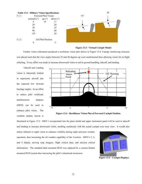
Further vision refinement produced a rectilinear vision plot shown in Figure 13.4. Canopy reinforcing structure<br />
was placed such that the view angles between 25 and 40 degrees up were unobstructed thus allowing vision for in-flight<br />
refueling. Every effort was made to increase downward vision to aid in ground handling, takeoff, and landing.<br />
Takeoff and Landing<br />
vision is inherently limited<br />
in supersonic aircraft due<br />
the required low forward<br />
fuselage angles. In an effort<br />
to reduce pilot workload,<br />
multifunction<br />
displays<br />
(MFD) can be used to<br />
enhance pilot vision. The<br />
vendetta display layout is<br />
Figure 13.4 - Rectilinear Vision Plot of Forward Cockpit Position<br />
illustrated in Figure 13.5. MFD 1 incorporated into the glare shield and upper instrument panel will be used in takeoff<br />
and landing to increase downward vision, meshing seamlessly with the actual cockpit over nose view. It would also<br />
utilize infrared or night vision to enhance visibility during night and poor weather<br />
operation, thus increasing the all weather capability of the <strong>Vendetta</strong>. MFD’s 2, 3,<br />
and 4 display moving map imagery, flight critical data, and mission critical<br />
information. The standard dash mounted HUD was replaced by a current helmet<br />
mounted HUD system thus increasing the pilot’s situational awareness.<br />
Figure 13.5 - Cockpit Displays<br />
72


