

Vendetta Final Proposal Part 2 - Cal Poly
Vendetta Final Proposal Part 2 - Cal Poly
Vendetta Final Proposal Part 2 - Cal Poly

Create successful ePaper yourself
Turn your PDF publications into a flip-book with our unique Google optimized e-Paper software.
utilized for fuel capacity. The remaining fuel tank volume was left for self sealing linings, structure, and fuel expansion<br />
(See Foldout 2). All tanks in the aircraft are pressurized with nitrogen gas from the onboard inert gas generating system<br />
(OBIGGS). Pressurization is minimal due to structural constraints and the low vapor pressure of JP-8. Nitrogen reduces<br />
the concentration of fuel vapor and thus the chance of an explosion. All tanks on the aircraft are self sealing and feature<br />
flame resistant overflow and exhaust venting.<br />
Single point fueling and de-fueling can be performed from a port on the starboard side of the forward fuselage<br />
(Foldout 4). This fueling point shares common lines with the AAR retractable fueling boom port located on the upper<br />
portion of the forward fuselage. Both ports offer fueling rates as high as 1,100 gpm, which is the maximum KC-10 fuel<br />
probe refueling rate (Table 14.II). Fuel is directed to the forward fuselage tank and then power transferred to the<br />
remaining three tanks. A gravity feed system can be utilized in flight in case of a failure of the power feed system. All<br />
major thermal transfer within the aircraft is performed by the fuel system. The air cooled fuel cooler utilizes inlet duct<br />
boundary layer and flow control diversion air to dissipate all kinetic heating experienced by the airframe as well as heat<br />
generated by onboard systems. Dual heat exchangers are utilized for combat survivability. Fuel flow rate requirements<br />
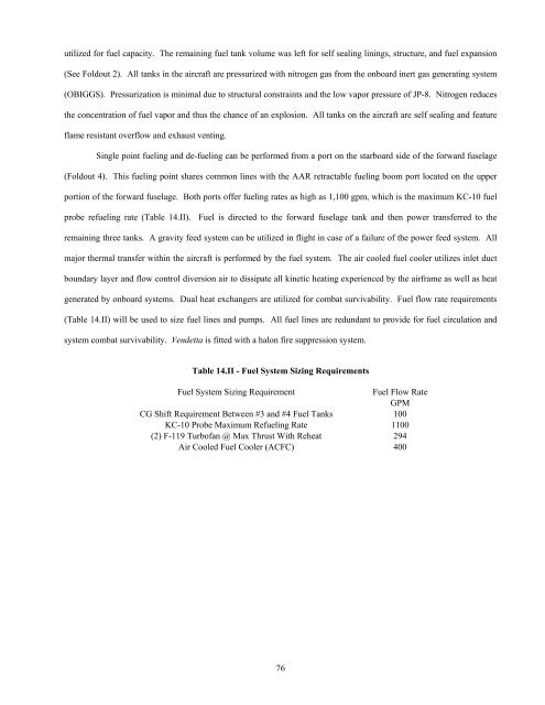
(Table 14.II) will be used to size fuel lines and pumps. All fuel lines are redundant to provide for fuel circulation and<br />
system combat survivability. <strong>Vendetta</strong> is fitted with a halon fire suppression system.<br />
Table 14.II - Fuel System Sizing Requirements<br />
Fuel System Sizing Requirement<br />
Fuel Flow Rate<br />
GPM<br />
CG Shift Requirement Between #3 and #4 Fuel Tanks 100<br />
KC-10 Probe Maximum Refueling Rate 1100<br />
(2) F-119 Turbofan @ Max Thrust With Reheat 294<br />
Air Cooled Fuel Cooler (ACFC) 400<br />
76


