80C186EB/80C188EB Microprocessor User's Manual - CEUNES
80C186EB/80C188EB Microprocessor User's Manual - CEUNES
80C186EB/80C188EB Microprocessor User's Manual - CEUNES

You also want an ePaper? Increase the reach of your titles
YUMPU automatically turns print PDFs into web optimized ePapers that Google loves.
<strong>80C186EB</strong>/<strong>80C188EB</strong><strong>Microprocessor</strong>User’s <strong>Manual</strong>
<strong>80C186EB</strong>/<strong>80C188EB</strong><strong>Microprocessor</strong>User’s <strong>Manual</strong>February 1995
Information in this document is provided solely to enable use of Intel products. Intel assumes no liability whatsoever, includinginfringement of any patent or copyright, for sale and use of Intel products except as provided in Intel’s Terms and Conditionsof Sale for such products.Intel Corporation makes no warranty for the use of its products and assumes no responsibility for any errors which may appearin this document nor does it make a commitment to update the information contained herein.Intel retains the right to make changes to these specifications at any time, without notice.Contact your local Intel sales office or your distributor to obtain the latest specifications before placing your product order.MDS is an ordering code only and is not used as a product name or trademark of Intel Corporation.Intel Corporation and Intel's FASTPATH are not affiliated with Kinetics, a division of Excelan, Inc. or its FASTPATH trademarkor products.*Other brands and names are the property of their respective owners.Additional copies of this document or other Intel literature may be obtained from:Intel CorporationLiterature SalesP.O. Box 7641Mt. Prospect, IL 60056-7641or call 1-800-879-4683© INTEL CORPORATION, 1995
CONTENTSCHAPTER 1INTRODUCTION1.1 HOW TO USE THIS MANUAL....................................................................................... 1-21.2 RELATED DOCUMENTS .............................................................................................. 1-31.3 CUSTOMER SERVICE.................................................................................................. 1-41.3.1 How to Use Intel's FaxBack Service .........................................................................1-51.3.2 How to Use Intel's Application BBS ..........................................................................1-51.3.3 How to Find the Latest ApBUILDER Files, Hypertext <strong>Manual</strong>s, andData Sheets on the BBS ............................................................................................1-6CHAPTER 2OVERVIEW OF THE 80C186 FAMILY ARCHITECTURE2.1 ARCHITECTURAL OVERVIEW .................................................................................... 2-12.1.1 Execution Unit ...........................................................................................................2-22.1.2 Bus Interface Unit .....................................................................................................2-32.1.3 General Registers .....................................................................................................2-42.1.4 Segment Registers ...................................................................................................2-52.1.5 Instruction Pointer .....................................................................................................2-62.1.6 Flags .........................................................................................................................2-72.1.7 Memory Segmentation ..............................................................................................2-82.1.8 Logical Addresses ...................................................................................................2-102.1.9 Dynamically Relocatable Code ...............................................................................2-132.1.10 Stack Implementation .............................................................................................2-152.1.11 Reserved Memory and I/O Space ...........................................................................2-152.2 SOFTWARE OVERVIEW ............................................................................................ 2-172.2.1 Instruction Set .........................................................................................................2-172.2.1.1 Data Transfer Instructions .............................................................................2-182.2.1.2 Arithmetic Instructions ...................................................................................2-192.2.1.3 Bit Manipulation Instructions .........................................................................2-212.2.1.4 String Instructions ..........................................................................................2-222.2.1.5 Program Transfer Instructions .......................................................................2-232.2.1.6 Processor Control Instructions ......................................................................2-272.2.2 Addressing Modes ..................................................................................................2-272.2.2.1 Register and Immediate Operand Addressing Modes ...................................2-272.2.2.2 Memory Addressing Modes ...........................................................................2-282.2.2.3 I/O Port Addressing .......................................................................................2-362.2.2.4 Data Types Used in the 80C186 Modular Core Family .................................2-372.3 INTERRUPTS AND EXCEPTION HANDLING ............................................................ 2-392.3.1 Interrupt/Exception Processing ...............................................................................2-392.3.1.1 Non-Maskable Interrupts ...............................................................................2-422.3.1.2 Maskable Interrupts .......................................................................................2-432.3.1.3 Exceptions .....................................................................................................2-43iii
CONTENTS2.3.2 Software Interrupts ..................................................................................................2-452.3.3 Interrupt Latency .....................................................................................................2-452.3.4 Interrupt Response Time ........................................................................................2-462.3.5 Interrupt and Exception Priority ...............................................................................2-46CHAPTER 3BUS INTERFACE UNIT3.1 MULTIPLEXED ADDRESS AND DATA BUS................................................................ 3-13.2 ADDRESS AND DATA BUS CONCEPTS..................................................................... 3-13.2.1 16-Bit Data Bus .........................................................................................................3-13.2.2 8-Bit Data Bus ...........................................................................................................3-53.3 MEMORY AND I/O INTERFACES................................................................................. 3-63.3.1 16-Bit Bus Memory and I/O Requirements ...............................................................3-73.3.2 8-Bit Bus Memory and I/O Requirements .................................................................3-73.4 BUS CYCLE OPERATION ............................................................................................ 3-73.4.1 Address/Status Phase ............................................................................................3-103.4.2 Data Phase .............................................................................................................3-133.4.3 Wait States ..............................................................................................................3-133.4.4 Idle States ...............................................................................................................3-183.5 BUS CYCLES .............................................................................................................. 3-203.5.1 Read Bus Cycles ....................................................................................................3-203.5.1.1 Refresh Bus Cycles .......................................................................................3-223.5.2 Write Bus Cycles .....................................................................................................3-223.5.3 Interrupt Acknowledge Bus Cycle ...........................................................................3-253.5.3.1 System Design Considerations .....................................................................3-273.5.4 HALT Bus Cycle ......................................................................................................3-283.5.5 Temporarily Exiting the HALT Bus State .................................................................3-303.5.6 Exiting HALT ...........................................................................................................3-323.6 SYSTEM DESIGN ALTERNATIVES ........................................................................... 3-343.6.1 Buffering the Data Bus ............................................................................................3-353.6.2 Synchronizing Software and Hardware Events .......................................................3-373.6.3 Using a Locked Bus ................................................................................................3-383.7 MULTI-MASTER BUS SYSTEM DESIGNS................................................................. 3-393.7.1 Entering Bus HOLD ................................................................................................3-393.7.1.1 HOLD Bus Latency ........................................................................................3-403.7.1.2 Refresh Operation During a Bus HOLD ........................................................3-413.7.2 Exiting HOLD ..........................................................................................................3-433.8 BUS CYCLE PRIORITIES ........................................................................................... 3-44iv
CONTENTSCHAPTER 4PERIPHERAL CONTROL BLOCK4.1 PERIPHERAL CONTROL REGISTERS........................................................................ 4-14.2 PCB RELOCATION REGISTER.................................................................................... 4-14.3 RESERVED LOCATIONS ............................................................................................. 4-44.4 ACCESSING THE PERIPHERAL CONTROL BLOCK.................................................. 4-44.4.1 Bus Cycles ...............................................................................................................4-44.4.2 READY Signals and Wait States .............................................................................4-44.4.3 F-Bus Operation .......................................................................................................4-54.4.3.1 Writing the PCB Relocation Register ...............................................................4-64.4.3.2 Accessing the Peripheral Control Registers ....................................................4-64.4.3.3 Accessing Reserved Locations .......................................................................4-64.5 SETTING THE PCB BASE LOCATION......................................................................... 4-64.5.1 Considerations for the 80C187 Math Coprocessor Interface ....................................4-7CHAPTER 5CLOCK GENERATION AND POWER MANAGEMENT5.1 CLOCK GENERATION.................................................................................................. 5-15.1.1 Crystal Oscillator .......................................................................................................5-15.1.1.1 Oscillator Operation .........................................................................................5-25.1.1.2 Selecting Crystals ............................................................................................5-55.1.2 Using an External Oscillator ......................................................................................5-65.1.3 Output from the Clock Generator ..............................................................................5-65.1.4 Reset and Clock Synchronization .............................................................................5-65.2 POWER MANAGEMENT............................................................................................. 5-105.2.1 Idle Mode ................................................................................................................5-115.2.1.1 Entering Idle Mode ........................................................................................5-115.2.1.2 Bus Operation During Idle Mode ...................................................................5-135.2.1.3 Leaving Idle Mode .........................................................................................5-145.2.1.4 Example Idle Mode Initialization Code ..........................................................5-155.2.2 Powerdown Mode ...................................................................................................5-165.2.2.1 Entering Powerdown Mode ...........................................................................5-175.2.2.2 Leaving Powerdown Mode ............................................................................5-185.2.3 Implementing a Power Management Scheme ........................................................5-19CHAPTER 6CHIP-SELECT UNIT6.1 COMMON METHODS FOR GENERATING CHIP-SELECTS....................................... 6-16.2 CHIP-SELECT UNIT FEATURES AND BENEFITS ...................................................... 6-16.3 CHIP-SELECT UNIT FUNCTIONAL OVERVIEW ......................................................... 6-26.4 PROGRAMMING........................................................................................................... 6-56.4.1 Initialization Sequence ..............................................................................................6-66.4.2 Start Address ..........................................................................................................6-106.4.3 Stop Address ..........................................................................................................6-10v
CONTENTS6.4.4 Enabling and Disabling Chip-Selects ......................................................................6-116.4.5 Bus Wait State and Ready Control .........................................................................6-116.4.6 Overlapping Chip-Selects .......................................................................................6-126.4.7 Memory or I/O Bus Cycle Decoding ........................................................................6-146.4.8 Programming Considerations ..................................................................................6-146.5 CHIP-SELECTS AND BUS HOLD............................................................................... 6-156.6 EXAMPLES ................................................................................................................. 6-156.6.1 Example 1: Typical System Configuration ..............................................................6-156.6.2 Example 2: Detecting Attempts to Access Guarded Memory .................................6-20CHAPTER 7REFRESH CONTROL UNIT7.1 THE ROLE OF THE REFRESH CONTROL UNIT......................................................... 7-27.2 REFRESH CONTROL UNIT CAPABILITIES................................................................. 7-27.3 REFRESH CONTROL UNIT OPERATION.................................................................... 7-27.4 REFRESH ADDRESSES............................................................................................... 7-47.5 REFRESH BUS CYCLES.............................................................................................. 7-57.6 GUIDELINES FOR DESIGNING DRAM CONTROLLERS............................................ 7-57.7 PROGRAMMING THE REFRESH CONTROL UNIT..................................................... 7-77.7.1 Calculating the Refresh Interval ................................................................................7-77.7.2 Refresh Control Unit Registers .................................................................................7-77.7.2.1 Refresh Base Address Register ......................................................................7-77.7.2.2 Refresh Clock Interval Register .......................................................................7-87.7.2.3 Refresh Control Register .................................................................................7-97.7.2.4 Refresh Address Register .............................................................................7-107.7.3 Programming Example ...........................................................................................7-117.8 REFRESH OPERATION AND BUS HOLD.................................................................. 7-13CHAPTER 8INTERRUPT CONTROL UNIT8.1 FUNCTIONAL OVERVIEW............................................................................................ 8-18.1.1 Generic Functions .....................................................................................................8-28.1.1.1 Interrupt Masking .............................................................................................8-28.1.1.2 Interrupt Priority ...............................................................................................8-38.1.1.3 Interrupt Nesting ..............................................................................................8-48.2 FUNCTIONAL OPERATION.......................................................................................... 8-48.2.1 Typical Interrupt Sequence .......................................................................................8-58.2.2 Priority Resolution .....................................................................................................8-58.2.2.1 Priority Resolution Example ............................................................................8-68.2.2.2 Interrupts That Share a Single Source ............................................................8-78.2.3 Cascading with External 8259As ..............................................................................8-78.2.3.1 Special Fully Nested Mode ..............................................................................8-88.2.4 Interrupt Acknowledge Sequence .............................................................................8-98.2.5 Polling .......................................................................................................................8-9vi
CONTENTS8.2.6 Edge and Level Triggering ......................................................................................8-108.2.7 Additional Latency and Response Time .................................................................8-108.3 PROGRAMMING THE INTERRUPT CONTROL UNIT ............................................... 8-118.3.1 Interrupt Control Registers ......................................................................................8-128.3.2 Interrupt Request Register ......................................................................................8-168.3.3 Interrupt Mask Register ...........................................................................................8-178.3.4 Priority Mask Register .............................................................................................8-188.3.5 In-Service Register .................................................................................................8-188.3.6 Poll and Poll Status Registers .................................................................................8-198.3.7 End-of-Interrupt (EOI) Register ...............................................................................8-218.3.8 Interrupt Status Register .........................................................................................8-228.3.9 Initializing the Interrupt Control Unit ........................................................................8-23CHAPTER 9TIMER/COUNTER UNIT9.1 FUNCTIONAL OVERVIEW............................................................................................ 9-19.2 PROGRAMMING THE TIMER/COUNTER UNIT .......................................................... 9-69.2.1 Initialization Sequence ............................................................................................9-119.2.2 Clock Sources .........................................................................................................9-129.2.3 Counting Modes ......................................................................................................9-129.2.3.1 Retriggering ...................................................................................................9-139.2.4 Pulsed and Variable Duty Cycle Output ..................................................................9-149.2.5 Enabling/Disabling Counters ...................................................................................9-159.2.6 Timer Interrupts .......................................................................................................9-169.2.7 Programming Considerations ..................................................................................9-169.3 TIMING ........................................................................................................................ 9-169.3.1 Input Setup and Hold Timings .................................................................................9-169.3.2 Synchronization and Maximum Frequency .............................................................9-179.3.2.1 Timer/Counter Unit Application Examples .....................................................9-179.3.3 Real-Time Clock .....................................................................................................9-179.3.4 Square-Wave Generator .........................................................................................9-179.3.5 Digital One-Shot ......................................................................................................9-17CHAPTER 10SERIAL COMMUNICATIONS UNIT10.1 INTRODUCTION ......................................................................................................... 10-110.1.1 Asynchronous Communications ..............................................................................10-110.1.1.1 RX Machine ...................................................................................................10-210.1.1.2 TX Machine ...................................................................................................10-410.1.1.3 Modes 1, 3 and 4 ...........................................................................................10-610.1.1.4 Mode 2 ..........................................................................................................10-710.1.2 Synchronous Communications ...............................................................................10-810.2 PROGRAMMING......................................................................................................... 10-910.2.1 Baud Rates ...........................................................................................................10-10vii
CONTENTS10.2.2 Asynchronous Mode Programming .......................................................................10-1310.2.2.1 Modes 1, 3 and 4 for Stand-alone Serial Communications .........................10-1310.2.2.2 Modes 2 and 3 for Multiprocessor Communications ...................................10-1410.2.2.3 Sending and Receiving a Break Character .................................................10-1410.2.3 Programming in Mode 0 ........................................................................................10-1810.3 HARDWARE CONSIDERATIONS FOR THE SERIAL PORT ................................... 10-1810.3.1 CTS Pin Timings ...................................................................................................10-1810.3.2 BCLK Pin Timings .................................................................................................10-1810.3.3 Mode 0 Timings ....................................................................................................10-2010.3.3.1 CLKOUT as Baud Timebase Clock .............................................................10-2010.3.3.2 BCLK as Baud Timebase Clock ..................................................................10-2110.4 SERIAL COMMUNICATIONS UNIT INTERRUPTS .................................................. 10-2110.4.1 Channel 0 Interrupts .............................................................................................10-2110.4.2 Channel 1 Interrupts .............................................................................................10-2110.5 SERIAL PORT EXAMPLES....................................................................................... 10-2310.5.1 Asynchronous Mode Example ..............................................................................10-2310.5.2 Mode 0 Example ...................................................................................................10-2610.5.3 Master/Slave Example ..........................................................................................10-27CHAPTER 11INPUT/OUTPUT PORTS11.1 FUNCTIONAL OVERVIEW.......................................................................................... 11-111.1.1 Bidirectional Port .....................................................................................................11-111.1.2 Input Port ................................................................................................................11-311.1.3 Output Port ..............................................................................................................11-311.1.4 Open-Drain Bidirectional Port .................................................................................11-311.1.5 Port Pin Organization ..............................................................................................11-311.1.5.1 Port 1 Organization .......................................................................................11-711.1.5.2 Port 2 Organization .......................................................................................11-711.2 PROGRAMMING THE I/O PORT UNIT....................................................................... 11-711.2.1 Port Control Register ..............................................................................................11-811.2.2 Port Direction Register ............................................................................................11-811.2.3 Port Data Latch Register .........................................................................................11-911.2.4 Port Pin State Register .........................................................................................11-1011.2.5 Initializing the I/O Ports .........................................................................................11-1111.3 PROGRAMMING EXAMPLE..................................................................................... 11-12CHAPTER 12MATH COPROCESSING12.1 OVERVIEW OF MATH COPROCESSING.................................................................. 12-112.2 AVAILABILITY OF MATH COPROCESSING.............................................................. 12-112.3 THE 80C187 MATH COPROCESSOR........................................................................ 12-212.3.1 80C187 Instruction Set ...........................................................................................12-212.3.1.1 Data Transfer Instructions .............................................................................12-3viii
CONTENTS12.3.1.2 Arithmetic Instructions ...................................................................................12-312.3.1.3 Comparison Instructions ................................................................................12-512.3.1.4 Transcendental Instructions ..........................................................................12-512.3.1.5 Constant Instructions .....................................................................................12-612.3.1.6 Processor Control Instructions ......................................................................12-612.3.2 80C187 Data Types ................................................................................................12-712.4 MICROPROCESSOR AND COPROCESSOR OPERATION...................................... 12-712.4.1 Clocking the 80C187 .............................................................................................12-1012.4.2 Processor Bus Cycles Accessing the 80C187 ......................................................12-1012.4.3 System Design Tips ..............................................................................................12-1112.4.4 Exception Trapping ...............................................................................................12-13CHAPTER 13ONCE MODE13.1 ENTERING/LEAVING ONCE MODE........................................................................... 13-1APPENDIX A80C186 INSTRUCTION SET ADDITIONS AND EXTENSIONSA.1 80C186 INSTRUCTION SET ADDITIONS ................................................................... A-1A.1.1 Data Transfer Instructions ...................................................................................... A-1A.1.2 String Instructions ................................................................................................... A-2A.1.3 High-Level Instructions ........................................................................................... A-2A.2 80C186 INSTRUCTION SET ENHANCEMENTS......................................................... A-8A.2.1 Data Transfer Instructions ...................................................................................... A-8A.2.2 Arithmetic Instructions ............................................................................................ A-9A.2.3 Bit Manipulation Instructions ................................................................................... A-9A.2.3.1 Shift Instructions ............................................................................................. A-9A.2.3.2 Rotate Instructions ....................................................................................... A-10APPENDIX BINPUT SYNCHRONIZATIONB.1 WHY SYNCHRONIZERS ARE REQUIRED................................................................. B-1B.2 ASYNCHRONOUS PINS.............................................................................................. B-2APPENDIX CINSTRUCTION SET DESCRIPTIONSAPPENDIX DINSTRUCTION SET OPCODES AND CLOCK CYCLESINDEXix
CONTENTSFIGURESFigurePage2-1 Simplified Functional Block Diagram of the 80C186 Family CPU ................................2-22-2 Physical Address Generation .......................................................................................2-32-3 General Registers ........................................................................................................2-42-4 Segment Registers.......................................................................................................2-62-5 Processor Status Word ................................................................................................2-92-6 Segment Locations in Physical Memory.....................................................................2-102-7 Currently Addressable Segments...............................................................................2-112-8 Logical and Physical Address ....................................................................................2-122-9 Dynamic Code Relocation..........................................................................................2-142-10 Stack Operation..........................................................................................................2-162-11 Flag Storage Format ..................................................................................................2-192-12 Memory Address Computation...................................................................................2-292-13 Direct Addressing .......................................................................................................2-302-14 Register Indirect Addressing ......................................................................................2-312-15 Based Addressing ......................................................................................................2-312-16 Accessing a Structure with Based Addressing...........................................................2-322-17 Indexed Addressing....................................................................................................2-332-18 Accessing an Array with Indexed Addressing ............................................................2-332-19 Based Index Addressing ............................................................................................2-342-20 Accessing a Stacked Array with Based Index Addressing .........................................2-352-21 String Operand ...........................................................................................................2-362-22 I/O Port Addressing ....................................................................................................2-362-23 80C186 Modular Core Family Supported Data Types................................................2-382-24 Interrupt Control Unit ..................................................................................................2-392-25 Interrupt Vector Table.................................................................................................2-402-26 Interrupt Sequence.....................................................................................................2-422-27 Interrupt Response Factors........................................................................................2-462-28 Simultaneous NMI and Exception ..............................................................................2-472-29 Simultaneous NMI and Single Step Interrupts............................................................2-482-30 Simultaneous NMI, Single Step and Maskable Interrupt............................................2-493-1 Physical Data Bus Models............................................................................................3-23-2 16-Bit Data Bus Byte Transfers....................................................................................3-33-3 16-Bit Data Bus Even Word Transfers .........................................................................3-43-4 16-Bit Data Bus Odd Word Transfers...........................................................................3-53-5 8-Bit Data Bus Word Transfers.....................................................................................3-63-6 Typical Bus Cycle.........................................................................................................3-83-7 T-State Relation to CLKOUT........................................................................................3-83-8 BIU State Diagram .......................................................................................................3-93-9 T-State and Bus Phases ............................................................................................3-103-10 Address/Status Phase Signal Relationships ..............................................................3-113-11 Demultiplexing Address Information...........................................................................3-123-12 Data Phase Signal Relationships ...............................................................................3-143-13 Typical Bus Cycle with Wait States ............................................................................3-153-14 READY Pin Block Diagram.........................................................................................3-15x
CONTENTSFIGURESFigurePage3-15 Generating a Normally Not-Ready Bus Signal ...........................................................3-163-16 Generating a Normally Ready Bus Signal..................................................................3-173-17 Normally Not-Ready System Timing ..........................................................................3-183-18 Normally Ready System Timings ...............................................................................3-193-19 Typical Read Bus Cycle .............................................................................................3-213-20 Read-Only Device Interface .......................................................................................3-223-21 Typical Write Bus Cycle..............................................................................................3-233-22 16-Bit Bus Read/Write Device Interface.....................................................................3-243-23 Interrupt Acknowledge Bus Cycle...............................................................................3-263-24 Typical 82C59A Interface ...........................................................................................3-273-25 HALT Bus Cycle .........................................................................................................3-303-26 Returning to HALT After a HOLD/HLDA Bus Exchange ............................................3-313-27 Returning to HALT After a Refresh Bus Cycle ...........................................................3-323-28 Exiting HALT (Powerdown Mode) ..............................................................................3-333-29 Exiting HALT (Active/Idle Mode).................................................................................3-343-30 DEN and DT/R Timing Relationships .........................................................................3-353-31 Buffered AD Bus System............................................................................................3-363-32 Qualifying DEN with Chip-Selects ..............................................................................3-373-33 Timing Sequence Entering HOLD ..............................................................................3-403-34 Refresh Request During HOLD..................................................................................3-423-35 Latching HLDA ...........................................................................................................3-433-36 Exiting HOLD..............................................................................................................3-444-1 PCB Relocation Register..............................................................................................4-25-1 Clock Generator ...........................................................................................................5-15-2 Ideal Operation of Pierce Oscillator..............................................................................5-25-3 Crystal Connections to <strong>Microprocessor</strong>........................................................................5-35-4 Equations for Crystal Calculations................................................................................5-45-5 Simple RC Circuit for Powerup Reset ..........................................................................5-75-6 Cold Reset Waveform ..................................................................................................5-85-7 Warm Reset Waveform ................................................................................................5-95-8 Clock Synchronization at Reset..................................................................................5-105-9 Power Control Register ..............................................................................................5-125-10 Entering Idle Mode .....................................................................................................5-135-11 HOLD/HLDA During Idle Mode...................................................................................5-145-12 Entering Powerdown Mode ........................................................................................5-175-13 Powerdown Timer Circuit ...........................................................................................5-186-1 Common Chip-Select Generation Methods..................................................................6-26-2 Chip-Select Block Diagram...........................................................................................6-36-3 Chip-Select Relative Timings .......................................................................................6-46-4 UCS Reset Configuration .............................................................................................6-56-5 START Register Definition ...........................................................................................6-76-6 STOP Register Definition .............................................................................................6-86-7 Wait State and Ready Control Functions ...................................................................6-126-8 Overlapping Chip-Selects...........................................................................................6-13xi
CONTENTSFIGURESFigurePage6-9 Using Chip-Selects During HOLD ..............................................................................6-156-10 Typical System ...........................................................................................................6-166-11 Guarded Memory Detector.........................................................................................6-207-1 Refresh Control Unit Block Diagram.............................................................................7-17-2 Refresh Control Unit Operation Flow Chart..................................................................7-37-3 Refresh Address Formation..........................................................................................7-47-4 Suggested DRAM Control Signal Timing Relationships...............................................7-67-5 Formula for Calculating Refresh Interval for RFTIME Register....................................7-77-6 Refresh Base Address Register ...................................................................................7-87-7 Refresh Clock Interval Register....................................................................................7-97-8 Refresh Control Register............................................................................................7-107-9 Refresh Address Register ..........................................................................................7-117-10 Regaining Bus Control to Run a DRAM Refresh Bus Cycle......................................7-148-1 Interrupt Control Unit Block Diagram............................................................................8-28-2 Using External 8259A Modules in Cascade Mode .......................................................8-88-3 Interrupt Control Unit Latency and Response Time ...................................................8-118-4 Interrupt Control Register for Internal Sources...........................................................8-138-5 Interrupt Control Register for Noncascadable External Pins......................................8-148-6 Interrupt Control Register for Cascadable Interrupt Pins............................................8-158-7 Interrupt Request Register .........................................................................................8-168-8 Interrupt Mask Register ..............................................................................................8-178-9 Priority Mask Register ................................................................................................8-188-10 In-Service Register.....................................................................................................8-198-11 Poll Register ...............................................................................................................8-208-12 Poll Status Register....................................................................................................8-218-13 End-of-Interrupt Register............................................................................................8-228-14 Interrupt Status Register ............................................................................................8-239-1 Timer/Counter Unit Block Diagram...............................................................................9-29-2 Counter Element Multiplexing and Timer Input Synchronization..................................9-39-3 Timers 0 and 1 Flow Chart ...........................................................................................9-49-4 Timer/Counter Unit Output Modes................................................................................9-69-5 Timer 0 and Timer 1 Control Registers ........................................................................9-79-6 Timer 2 Control Register ..............................................................................................9-99-7 Timer Count Registers................................................................................................9-109-8 Timer Maxcount Compare Registers..........................................................................9-119-9 TxOUT Signal Timing .................................................................................................9-1510-1 Typical 10-Bit Asynchronous Data Frame..................................................................10-210-2 RX Machine................................................................................................................10-310-3 TX Machine ................................................................................................................10-510-4 Mode 1 Waveform ......................................................................................................10-610-5 Mode 3 Waveform ......................................................................................................10-710-6 Mode 4 Waveform ......................................................................................................10-710-7 Mode 0 Waveforms ....................................................................................................10-810-8 Serial Receive Buffer Register (SxRBUF)..................................................................10-9xii
CONTENTSFIGURESFigurePage10-9 Serial Transmit Buffer Register (SxTBUF) ...............................................................10-1010-10 Baud Rate Counter Register (BxCNT) .....................................................................10-1110-11 Baud Rate Compare Register (BxCMP)...................................................................10-1210-12 Calculating the BxCMP Value for a Specific Baud Rate...........................................10-1210-13 Serial Port Control Register (SxCON) ......................................................................10-1510-14 Serial Port Status Register (SxSTS).........................................................................10-1610-15 CTS Recognition Sequence ....................................................................................10-1910-16 BCLK Synchronization .............................................................................................10-1910-17 Mode 0, BxCMP > 2 .................................................................................................10-2010-18 Channel 0 Interrupts.................................................................................................10-2210-19 Channel 1 Interrupts.................................................................................................10-2210-20 Master/Slave Example .............................................................................................10-2811-1 Simplified Logic Diagram of a Bidirectional Port Pin ..................................................11-211-2 Simplified Logic Diagram of an Input Port Pin............................................................11-411-3 Simplified Logic Diagram of an Output Port Pin .........................................................11-511-4 Simplified Logic Diagram of an Open-Drain Bidirectional Port...................................11-611-5 Port Control Register (PxCON) ..................................................................................11-811-6 Port Direction Register (PxDIR)..................................................................................11-911-7 Port Data Latch Register (PxLTCH) .........................................................................11-1011-8 Port Pin State Register (PxPIN) ...............................................................................11-1112-1 80C187-Supported Data Types..................................................................................12-812-2 80C186 Modular Core Family/80C187 System Configuration....................................12-912-3 80C187 Configuration with a Partially Buffered Bus.................................................12-1212-4 80C187 Exception Trapping via Processor Interrupt Pin..........................................12-1413-1 Entering/Leaving ONCE Mode ...................................................................................13-1A-1 Formal Definition of ENTER ........................................................................................ A-3A-2 Variable Access in Nested Procedures ....................................................................... A-4A-3 Stack Frame for Main at Level 1.................................................................................. A-4A-4 Stack Frame for Procedure A at Level 2 ..................................................................... A-5A-5 Stack Frame for Procedure B at Level 3 Called from A............................................... A-6A-6 Stack Frame for Procedure C at Level 3 Called from B .............................................. A-7B-1 Input Synchronization Circuit....................................................................................... B-1xiii
CONTENTSTableTABLESPage1-1 Comparison of 80C186 Modular Core Family Products...............................................1-21-2 Related Documents and Software................................................................................1-32-1 Implicit Use of General Registers.................................................................................2-52-2 Logical Address Sources............................................................................................2-132-3 Data Transfer Instructions ..........................................................................................2-182-4 Arithmetic Instructions ................................................................................................2-202-5 Arithmetic Interpretation of 8-Bit Numbers .................................................................2-212-6 Bit Manipulation Instructions ......................................................................................2-212-7 String Instructions.......................................................................................................2-222-8 String Instruction Register and Flag Use....................................................................2-232-9 Program Transfer Instructions....................................................................................2-252-10 Interpretation of Conditional Transfers .......................................................................2-262-11 Processor Control Instructions ...................................................................................2-272-12 Supported Data Types ...............................................................................................2-373-1 Bus Cycle Types ........................................................................................................3-123-2 Read Bus Cycle Types...............................................................................................3-203-3 Read Cycle Critical Timing Parameters......................................................................3-203-4 Write Bus Cycle Types ...............................................................................................3-233-5 Write Cycle Critical Timing Parameters......................................................................3-253-6 HALT Bus Cycle Pin States........................................................................................3-293-7 Signal Condition Entering HOLD................................................................................3-404-1 Peripheral Control Block...............................................................................................4-35-1 Suggested Values for Inductor L1 in Third Overtone Oscillator Circuit ........................5-45-2 Summary of Power Management Modes ...................................................................5-196-1 Chip-Select Unit Registers ...........................................................................................6-56-2 Memory and I/O Compare Addresses........................................................................6-106-3 Example Adjustments for Overlapping Chip-Selects..................................................6-147-1 Identification of Refresh Bus Cycles.............................................................................7-58-1 Default Interrupt Priorities.............................................................................................8-38-2 Fixed Interrupt Types ...................................................................................................8-98-3 Interrupt Control Unit Registers..................................................................................8-119-1 Timer 0 and 1 Clock Sources .....................................................................................9-129-2 Timer Retriggering......................................................................................................9-1310-1 BxCMP Values for Typical Baud Rates and CPU Frequencies................................10-1311-1 Port 1 Multiplexing Options ........................................................................................11-711-2 Port 2 Multiplexing Options ........................................................................................11-712-1 80C187 Data Transfer Instructions.............................................................................12-312-2 80C187 Arithmetic Instructions...................................................................................12-412-3 80C187 Comparison Instructions ...............................................................................12-512-4 80C187 Transcendental Instructions..........................................................................12-512-5 80C187 Constant Instructions ....................................................................................12-612-6 80C187 Processor Control Instructions......................................................................12-612-7 80C187 I/O Port Assignments..................................................................................12-10C-1 Instruction Format Variables........................................................................................ C-1xiv
CONTENTSTableTABLESPageC-2 Instruction Operands ................................................................................................... C-2C-3 Flag Bit Functions........................................................................................................ C-3C-4 Instruction Set ............................................................................................................. C-4D-1 Operand Variables ...................................................................................................... D-1D-2 Instruction Set Summary ............................................................................................. D-2D-3 Machine Instruction Decoding Guide........................................................................... D-9D-4 Mnemonic Encoding Matrix (Left Half) ...................................................................... D-20D-5 Abbreviations for Mnemonic Encoding Matrix ........................................................... D-22xv
CONTENTSEXAMPLESExamplePage5-1 Initializing the Power Management Unit for Idle or Powerdown Mode .......................5-166-1 Initializing the Chip-Select Unit...................................................................................6-177-1 Initializing the Refresh Control Unit ............................................................................7-128-1 Initializing the Interrupt Control Unit ...........................................................................8-249-1 Configuring a Real-Time Clock...................................................................................9-189-2 Configuring a Square-Wave Generator......................................................................9-219-3 Configuring a Digital One-Shot...................................................................................9-2210-1 Asynchronous Mode 4 Example...............................................................................10-2310-2 Mode 0 Example ......................................................................................................10-2610-3 Master/Slave — Implementing the Master/Slave Routines ......................................10-2910-4 Master/Slave — The _select_slave Routine.............................................................10-3010-5 Master/Slave — The slave_1 Routine......................................................................10-3210-6 Master/Slave — The _send_slave_command Routine ............................................10-3511-1 I/O Port Programming Example................................................................................11-1212-1 Initialization Sequence for 80C187 Math Coprocessor ............................................12-1512-2 Floating Point Math Routine Using FSINCOS..........................................................12-16xvi
Introduction1
CHAPTER 1INTRODUCTIONThe 8086 microprocessor was first introduced in 1978 and gained rapid support as the microcomputerengine of choice. There are literally millions of 8086/8088-based systems in the world today.The amount of software written for the 8086/8088 is rivaled by no other architecture.By the early 1980’s, however, it was clear that a replacement for the 8086/8088 was necessary.An 8086/8088 system required dozens of support chips to implement even a moderately complexdesign. Intel recognized the need to integrate commonly used system peripherals onto the samesilicon die as the CPU. In 1982 Intel addressed this need by introducing the 80186/80188 familyof embedded microprocessors. The original 80186/80188 integrated an enhanced 8086/8088CPU with six commonly used system peripherals. A parallel effort within Intel also gave rise tothe 80286 microprocessor in 1982. The 80286 began the trend toward the very high performanceIntel architecture that today includes the Intel386, Intel486 and Pentium microprocessors.As technology advanced and turned toward small geometry CMOS processes, it became clearthat a new 80186 was needed. In 1987 Intel announced the second generation of the 80186 family:the 80C186/C188. The 80C186 family is pin compatible with the 80186 family, while adding anenhanced feature set. The high-performance CHMOS III process allowed the 80C186 to run attwice the clock rate of the NMOS 80186, while consuming less than one-fourth the power.The 80186 family took another major step in 1990 with the introduction of the <strong>80C186EB</strong> family.The <strong>80C186EB</strong> heralded many changes for the 80186 family. First, the enhanced 8086/8088 CPUwas redesigned as a static, stand-alone module known as the 80C186 Modular Core. Second, the80186 family peripherals were also redesigned as static modules with standard interfaces. Thegoal behind this redesign effort was to give Intel the capability to proliferate the 80186 familyrapidly, in order to provide solutions for an even wider range of customer applications.The <strong>80C186EB</strong>/C188EB was the first product to use the new modular capability. The<strong>80C186EB</strong>/C188EB includes a different peripheral set than the original 80186 family. Powerconsumption was dramatically reduced as a direct result of the static design, power managementfeatures and advanced CHMOS IV process. The <strong>80C186EB</strong>/C188EB has found acceptance in awide array of portable equipment ranging from cellular phones to personal organizers.In 1991 the 80C186 Modular Core family was again extended with the introduction of three newproducts: the 80C186XL, the 80C186EA and the 80C186EC. The 80C186XL/C188XL is a higherperformance, lower power replacement for the 80C186/C188. The 80C186EA/C188EA combinesthe feature set of the 80C186 with new power management features for power-criticalapplications. The 80C186EC/C188EC offers the highest level of integration of any of the 80C186Modular Core family products, with 14 on-chip peripherals (see Table 1-1).1-1
INTRODUCTIONThe 80C186 Modular Core family is the direct result of ten years of Intel development. It offersthe designer the peace of mind of a well-established architecture with the benefits of state-of-thearttechnology.Table 1-1. Comparison of 80C186 Modular Core Family ProductsFeature 80C186XL 80C186EA <strong>80C186EB</strong> 80C186ECEnhanced 8086 Instruction SetLow-Power Static Modular CPUPower-Save (Clock Divide) ModePowerdown and Idle Modes80C187 InterfaceONCE ModeInterrupt Control Unit 8259CompatibleTimer/Counter UnitChip-Select Unit Enhanced EnhancedDMA Unit 2 Channel 2 Channel 4 ChannelSerial Communications UnitRefresh Control Unit Enhanced EnhancedWatchdog Timer UnitI/O Ports 16 Total 22 Total1.1 HOW TO USE THIS MANUALThis manual uses phrases such as 80C186 Modular Core Family or 80C188 Modular Core, aswell as references to specific products such as 80C188EA. Each phrase refers to a specific set of80C186 family products. The phrases and the products they refer to are as follows:80C186 Modular Core Family: This phrase refers to any device that uses the modular80C186/C188 CPU core architecture. At this time these include the 80C186EA/C188EA,<strong>80C186EB</strong>/C188EB, 80C186EC/C188EC and 80C186XL/C188XL.80C186 Modular Core: Without the word family, this phrase refers only to the 16-bit bus membersof the 80C186 Modular Core Family.80C188 Modular Core: This phrase refers to the 8-bit bus products.80C188EC: A specific product reference refers only to the named device. For example, On the80C188EC… refers strictly to the 80C188EC and not to any other device.1-2
INTRODUCTIONEach chapter covers a specific section of the device, beginning with the CPU core. Each peripheralchapter includes programming examples intended to aid in your understanding of device operation.Please read the comments carefully, as not all of the examples include all the codenecessary for a specific application.This user’s guide is a supplement to the device data sheet. Specific timing values are not discussedin this guide. When designing a system, always consult the most recent version of the devicedata sheet for up-to-date specifications.1.2 RELATED DOCUMENTSThe following table lists documents and software that are useful in designing systems that incorporatethe 80C186 Modular Core Family. These documents are available through Intel Literature.In the U.S. and Canada, call 1-800-548-4725 to order. In Europe and other international locations,please contact your local Intel sales office or distributor.NOTEIf you will be transferring a design from the 80186/80188 or 80C186/80C188to the 80C186XL/80C188XL, refer to FaxBack Document No. 2132.Table 1-2. Related Documents and SoftwareDocument/Software TitleDocumentOrder No.Embedded <strong>Microprocessor</strong>s (includes 186 family data sheets) 272396186 Embedded <strong>Microprocessor</strong> Line Card 27207980186/80188 High-Integration 16-Bit <strong>Microprocessor</strong> Data Sheet 27243080C186XL/C188XL-20, -12 16-Bit High-Integration Embedded <strong>Microprocessor</strong> 272431Data Sheet80C186EA/80C188EA-20, -12 and 80L186EA/80L188EA-13, -8 (low power272432versions) 16-Bit High-Integration Embedded <strong>Microprocessor</strong> Data Sheet<strong>80C186EB</strong>/<strong>80C188EB</strong>-20, -13 and 80L186EB/80L188EB-13, -8 (low power272433versions) 16-Bit High-Integration Embedded <strong>Microprocessor</strong> Data Sheet80C186EC/80C188EC-20, -13 and 80L186EC/80L188EC-13, -8 (low power272434versions) 16-Bit High-Integration Embedded <strong>Microprocessor</strong> Data Sheet80C187 80-Bit Math Coprocessor Data Sheet 270640Low Voltage Embedded Design 27232480C186/C188, 80C186XL/C188XL <strong>Microprocessor</strong> User’s <strong>Manual</strong> 27216480C186EA/80C188EA <strong>Microprocessor</strong> User’s <strong>Manual</strong> 270950<strong>80C186EB</strong>/<strong>80C188EB</strong> <strong>Microprocessor</strong> User’s <strong>Manual</strong> 27083080C186EC/80C188EC <strong>Microprocessor</strong> User’s <strong>Manual</strong> 2720478086/8088/8087/80186/80188 Programmer’s Pocket Reference Guide 2310171-3
INTRODUCTIONTable 1-2. Related Documents and Software (Continued)Document/Software TitleDocumentOrder No.8086/8088 User’s <strong>Manual</strong> Programmer’s and Hardware Reference <strong>Manual</strong> 240487ApBUILDER Software 27221680C186EA Hypertext <strong>Manual</strong> 272275<strong>80C186EB</strong> Hypertext <strong>Manual</strong> 27229680C186EC Hypertext <strong>Manual</strong> 27229880C186XL Hypertext <strong>Manual</strong> 272630ZCON - Z80 Code ConverterAvailable on BBS1.3 CUSTOMER SERVICEThis section provides telephone numbers and describes various customer services.• Customer Support (U.S. and Canada) 800-628-8686• Customer Training (U.S. and Canada) 800-234-8806• Literature Fulfillment— 800-548-4725 (U.S. and Canada)— +44(0)793-431155 (Europe)• FaxBack* Service— 800-628-2283 (U.S. and Canada)— +44(0)793-496646 (Europe)— 916-356-3105 (worldwide)• Application Bulletin Board System— 916-356-3600 (worldwide, up to 14.4-Kbaud line)— 916-356-7209 (worldwide, dedicated 2400-baud line)— +44(0)793-496340 (Europe)Intel provides 24-hour automated technical support through the use of our FaxBack service andour centralized Intel Application Bulletin Board System (BBS). The FaxBack service is a simpleto-useinformation system that lets you order technical documents by phone for immediate deliveryto your fax machine. The BBS is a centralized computer bulletin board system that providesupdated application-specific information about Intel products.1-4
INTRODUCTION1.3.1 How to Use Intel's FaxBack ServiceThink of the FaxBack service as a library of technical documents that you can access with yourphone. Just dial the telephone number (see page 1-4) and respond to the system prompts. Afteryou select a document, the system sends a copy to your fax machine.Each document is assigned an order number and is listed in a subject catalog. First-time usersshould order the appropriate subject catalogs to get a complete listing of document order numbers.The following catalogs and information packets are available:1. Microcontroller, Flash, and iPLD catalog2. Development tool catalog3. System catalog4. DVI and multimedia catalog5. BBS catalog6. <strong>Microprocessor</strong> and peripheral catalog7. Quality and reliability catalog8. Technical questionnaire1.3.2 How to Use Intel's Application BBSThe Application Bulletin Board System (BBS) provides centralized access to information, softwaredrivers, firmware upgrades, and revised software. Any user with a modem and computer canaccess the BBS. Use the following modem settings.• 14400, N, 8, 1If your modem does not support 14.4K baud, the system provides auto configuration support for1200- through 14.4K-baud modems.To access the BBS, just dial the telephone number (see page 1-4) and respond to the systemprompts. During your first session, the system asks you to register with the system operator byentering your name and location. The system operator will then set up your access account within24 hours. At that time, you can access the files on the BBS. For a listing of files, call the FaxBackservice and order catalog #6 (the BBS catalog).1-5
INTRODUCTIONIf you encounter any difficulty accessing our high-speed modem, try our dedicated 2400-baudmodem (see page 1-4). Use the following modem settings.• 2400 baud, N, 8, 11.3.3 How to Find the Latest ApBUILDER Files, Hypertext <strong>Manual</strong>s, andData Sheets on the BBSThe latest ApBUILDER files and hypertext manuals and data sheets are available first from theBBS. To access the files:1. Select [F] from the BBS Main menu.2. Select [L] from the Intel Apps Files menu.3. The BBS displays the list of all area levels and prompts for the area number.4. Select [25] to choose the ApBUILDER / Hypertext area.5. Area level 25 has four sublevels: (1) General, (2) 196 Files, (3) 186 Files, and (4) 8051Files.6. Select [1] to find the latest ApBUILDER files or the number of the appropriate productfamilysublevel to find the hypertext manuals and data sheets.7. Enter the file number to tag the files you wish to download. The BBS displays the approximatedownload time for tagged files.1-6
Overview of the80C186 FamilyArchitecture2
CHAPTER 2OVERVIEW OF THE 80C186 FAMILYARCHITECTUREThe 80C186 Modular <strong>Microprocessor</strong> Core shares a common base architecture with the 8086,8088, 80186, 80188, 80286, Intel386 and Intel486 processors. The 80C186 Modular Coremaintains full object-code compatibility with the 8086/8088 family of 16-bit microprocessors,while adding hardware and software performance enhancements. Most instructions require fewerclocks to execute on the 80C186 Modular Core because of hardware enhancements in the BusInterface Unit and the Execution Unit. Several additional instructions simplify programming andreduce code size (see Appendix A, “80C186 Instruction Set Additions and Extensions”).2.1 ARCHITECTURAL OVERVIEWThe 80C186 Modular <strong>Microprocessor</strong> Core incorporates two separate processing units: an ExecutionUnit (EU) and a Bus Interface Unit (BIU). The Execution Unit is functionally identicalamong all family members. The Bus Interface Unit is configured for a 16-bit external data busfor the 80C186 core and an 8-bit external data bus for the 80C188 core. The two units interfacevia an instruction prefetch queue.The Execution Unit executes instructions; the Bus Interface Unit fetches instructions, reads operandsand writes results. Whenever the Execution Unit requires another opcode byte, it takes thebyte out of the prefetch queue. The two units can operate independently of one another and areable, under most circumstances, to overlap instruction fetches and execution.The 80C186 Modular Core family has a 16-bit Arithmetic Logic Unit (ALU). The ArithmeticLogic Unit performs 8-bit or 16-bit arithmetic and logical operations. It provides for data movementbetween registers, memory and I/O space.The 80C186 Modular Core family CPU allows for high-speed data transfer from one area ofmemory to another using string move instructions and between an I/O port and memory usingblock I/O instructions. The CPU also provides many conditional branch and control instructions.The 80C186 Modular Core architecture features 14 basic registers grouped as general registers,segment registers, pointer registers and status and control registers. The four 16-bit general-purposeregisters (AX, BX, CX and DX) can be used as operands for most arithmetic operations aseither 8- or 16-bit units. The four 16-bit pointer registers (SI, DI, BP and SP) can be used in arithmeticoperations and in accessing memory-based variables. Four 16-bit segment registers (CS,DS, SS and ES) allow simple memory partitioning to aid modular programming. The status andcontrol registers consist of an Instruction Pointer (IP) and the Processor Status Word (PSW) register,which contains flag bits. Figure 2-1 is a simplified CPU block diagram.2-1
OVERVIEW OF THE 80C186 FAMILY ARCHITECTUREAddress Bus (20 Bits)GeneralRegistersAHBHCHDHSPBPSIDIALBLCLDLALU Data Bus(16 Bits)ΣCSDSSSESIPInternalCommunicationsRegistersDataBus(16 Bits)TemporaryRegistersBusControlLogicExternalBusALUFlagsEUControlSystemInstruction Queue1 2 3 4 5 6Q Bus(8 Bits)Execution Unit(EU)Bus Interface Unit(BIU)A1012-0AFigure 2-1. Simplified Functional Block Diagram of the 80C186 Family CPU2.1.1 Execution UnitThe Execution Unit executes all instructions, provides data and addresses to the Bus InterfaceUnit and manipulates the general registers and the Processor Status Word. The 16-bit ALU withinthe Execution Unit maintains the CPU status and control flags and manipulates the general registersand instruction operands. All registers and data paths in the Execution Unit are 16 bits widefor fast internal transfers.2-2
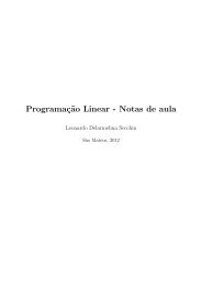
OVERVIEW OF THE 80C186 FAMILY ARCHITECTUREThe Execution Unit does not connect directly to the system bus. It obtains instructions from aqueue maintained by the Bus Interface Unit. When an instruction requires access to memory or aperipheral device, the Execution Unit requests the Bus Interface Unit to read and write data. Addressesmanipulated by the Execution Unit are 16 bits wide. The Bus Interface Unit, however,performs an address calculation that allows the Execution Unit to access the full megabyte ofmemory space.To execute an instruction, the Execution Unit must first fetch the object code byte from the instructionqueue and then execute the instruction. If the queue is empty when the Execution Unitis ready to fetch an instruction byte, the Execution Unit waits for the Bus Interface Unit to fetchthe instruction byte.2.1.2 Bus Interface UnitThe 80C186 Modular Core and 80C188 Modular Core Bus Interface Units are functionally identical.They are implemented differently to match the structure and performance characteristics oftheir respective system buses. The Bus Interface Unit executes all external bus cycles. This unitconsists of the segment registers, the Instruction Pointer, the instruction code queue and severalmiscellaneous registers. The Bus Interface Unit transfers data to and from the Execution Unit onthe ALU data bus.The Bus Interface Unit generates a 20-bit physical address in a dedicated adder. The adder shiftsa 16-bit segment value left 4 bits and then adds a 16-bit offset. This offset is derived from combinationsof the pointer registers, the Instruction Pointer and immediate values (see Figure 2-2).Any carry from this addition is ignored.Shift left 4 bits1234Segment Base1 2 3 4 01500202OffsetLogicalAddress190150+0022150= 1192 3 6 20To MemoryPhysical AddressA1500-0AFigure 2-2. Physical Address Generation2-3
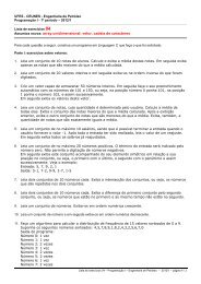
OVERVIEW OF THE 80C186 FAMILY ARCHITECTUREDuring periods when the Execution Unit is busy executing instructions, the Bus Interface Unitsequentially prefetches instructions from memory. As long as the prefetch queue is partially full,the Execution Unit fetches instructions.2.1.3 General RegistersThe 80C186 Modular Core family CPU has eight 16-bit general registers (see Figure 2-3). Thegeneral registers are subdivided into two sets of four registers. These sets are the data registers(also called the H & L group for high and low) and the pointer and index registers (also called theP & I group).15H8 7L0AHAXALAccumulatorDataGroupBHCHBXCXBLCLBaseCountDHDXDLDataSPStack PointerPointerandIndexGroupBPSIBase PointerSource IndexDIDestination IndexA1033-0AFigure 2-3. General Registers2-4
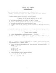
OVERVIEW OF THE 80C186 FAMILY ARCHITECTUREThe data registers can be addressed by their upper or lower halves. Each data register can be usedinterchangeably as a 16-bit register or two 8-bit registers. The pointer registers are always accessedas 16-bit values. The CPU can use data registers without constraint in most arithmetic and logicoperations. Arithmetic and logic operations can also use the pointer and index registers. Someinstructions use certain registers implicitly (see Table 2-1), allowing compact encoding.Table 2-1. Implicit Use of General RegistersRegisterAXALAHBXCXCLDXSPSIDIOperationsWord Multiply, Word Divide, Word I/OByte Multiply, Byte Divide, Byte I/O, Translate, Decimal ArithmeticByte Multiply, Byte DivideTranslateString Operations, LoopsVariable Shift and RotateWord Multiply, Word Divide, Indirect I/OStack OperationsString OperationsString OperationsThe contents of the general-purpose registers are undefined following a processor reset.2.1.4 Segment RegistersThe 80C186 Modular Core family memory space is 1 Mbyte in size and divided into logical segmentsof up to 64 Kbytes each. The CPU has direct access to four segments at a time. The segmentregisters contain the base addresses (starting locations) of these memory segments (see Figure2-4). The CS register points to the current code segment, which contains instructions to befetched. The SS register points to the current stack segment, which is used for all stack operations.The DS register points to the current data segment, which generally contains program variables.The ES register points to the current extra segment, which is typically used for data storage. TheCS register initializes to 0FFFFH, and the SS, DS and ES registers initialize to 0000H. Programscan access and manipulate the segment registers with several instructions.2-5
OVERVIEW OF THE 80C186 FAMILY ARCHITECTURE15 0CSDSSSESCode SegmentData SegmentStack SegmentExtra SegmentFigure 2-4. Segment Registers2.1.5 Instruction PointerThe Bus Interface Unit updates the 16-bit Instruction Pointer (IP) register so it contains the offsetof the next instruction to be fetched. Programs do not have direct access to the Instruction Pointer,but it can change, be saved or be restored as a result of program execution. For example, if theInstruction Pointer is saved on the stack, it is first automatically adjusted to point to the next instructionto be executed.Reset initializes the Instruction Pointer to 0000H. The CS and IP values comprise a starting executionaddress of 0FFFF0H (see “Logical Addresses” on page 2-10 for a description of addressformation).2-6
OVERVIEW OF THE 80C186 FAMILY ARCHITECTURE2.1.6 FlagsThe 80C186 Modular Core family has six status flags (see Figure 2-5) that the Execution Unitposts as the result of arithmetic or logical operations. Program branch instructions allow a programto alter its execution depending on conditions flagged by a prior operation. Different instructionsaffect the status flags differently, generally reflecting the following states:• If the Auxiliary Flag (AF) is set, there has been a carry out from the low nibble into the highnibble or a borrow from the high nibble into the low nibble of an 8-bit quantity (low-orderbyte of a 16-bit quantity). This flag is used by decimal arithmetic instructions.• If the Carry Flag (CF) is set, there has been a carry out of or a borrow into the high-order bitof the instruction result (8- or 16-bit). This flag is used by instructions that add or subtractmultibyte numbers. Rotate instructions can also isolate a bit in memory or a register byplacing it in the Carry Flag.• If the Overflow Flag (OF) is set, an arithmetic overflow has occurred. A significant digithas been lost because the size of the result exceeded the capacity of its destination location.An Interrupt On Overflow instruction is available that will generate an interrupt in thissituation.• If the Sign Flag (SF) is set, the high-order bit of the result is a 1. Since negative binarynumbers are represented in standard two’s complement notation, SF indicates the sign ofthe result (0 = positive, 1 = negative).• If the Parity Flag (PF) is set, the result has even parity, an even number of 1 bits. This flagcan be used to check for data transmission errors.• If the Zero Flag (ZF) is set, the result of the operation is zero.Additional control flags (see Figure 2-5) can be set or cleared by programs to alter processor operations:• Setting the Direction Flag (DF) causes string operations to auto-decrement. Strings areprocessed from high address to low address (or “right to left”). Clearing DF causes stringoperations to auto-increment. Strings are processed from low address to high address (or“left to right”).• Setting the Interrupt Enable Flag (IF) allows the CPU to recognize maskable external orinternal interrupt requests. Clearing IF disables these interrupts. The Interrupt Enable Flaghas no effect on software interrupts or non-maskable interrupts.• Setting the Trap Flag (TF) bit puts the processor into single-step mode for debugging. Inthis mode, the CPU automatically generates an interrupt after each instruction. This allowsa program to be inspected instruction by instruction during execution.The status and control flags are contained in a 16-bit Processor Status Word (see Figure 2-5). Resetinitializes the Processor Status Word to 0F000H.2-7
OVERVIEW OF THE 80C186 FAMILY ARCHITECTURE2.1.7 Memory SegmentationPrograms for the 80C186 Modular Core family view the 1 Mbyte memory space as a group ofuser-defined segments. A segment is a logical unit of memory that can be up to 64 Kbytes long.Each segment is composed of contiguous memory locations. Segments are independent and separatelyaddressable. Software assigns every segment a base address (starting location) in memoryspace. All segments begin on 16-byte memory boundaries. There are no other restrictions on segmentlocations. Segments can be adjacent, disjoint, partially overlapped or fully overlapped (seeFigure 2-6). A physical memory location can be mapped into (covered by) one or more logicalsegments.2-8
OVERVIEW OF THE 80C186 FAMILY ARCHITECTURERegister Name:Register Mnemonic:Register Function:Processor Status WordPSW (FLAGS)Posts CPU status information.15 0OFDFIFTFSFZFAFPFCFA1035-0ABitMnemonicBit NameResetStateFunctionOF Overflow Flag 0 If OF is set, an arithmetic overflow has occurred.DF Direction Flag 0IFInterruptEnable Flag0If DF is set, string instructions are processed highaddress to low address. If DF is clear, strings areprocessed low address to high address.If IF is set, the CPU recognizes maskable interruptrequests. If IF is clear, maskable interrupts areignored.TF Trap Flag 0 If TF is set, the processor enters single-step mode.SF Sign Flag 0If SF is set, the high-order bit of the result of anoperation is 1, indicating it is negative.ZF Zero Flag 0 If ZF is set, the result of an operation is zero.AF Auxiliary Flag 0PF Parity Flag 0If AF is set, there has been a carry from the lownibble to the high or a borrow from the high nibbleto the low nibble of an 8-bit quantity. Used in BCDoperations.If PF is set, the result of an operation has evenparity.CF Carry Flag 0If CF is set, there has been a carry out of, or aborrow into, the high-order bit of the result of aninstruction.NOTE: Reserved register bits are shown with gray shading. Reserved bits must be written to alogic zero to ensure compatibility with future Intel products.Figure 2-5. Processor Status Word2-9
OVERVIEW OF THE 80C186 FAMILY ARCHITECTUREFullyOverlappedPartlyOverlappedContiguousSegment DSegment CDisjointLogicalSegmentsSegment ASegment BSegment EPhysicalMemory0H 10000H 20000H 30000HA1036-0AFigure 2-6. Segment Locations in Physical MemoryThe four segment registers point to four “currently addressable” segments (see Figure 2-7). Thecurrently addressable segments provide a work space consisting of 64 Kbytes for code, a 64Kbytes for stack and 128 Kbytes for data storage. Programs access code and data in another segmentby updating the segment register to point to the new segment.2.1.8 Logical AddressesIt is useful to think of every memory location as having two kinds of addresses, physical and logical.A physical address is a 20-bit value that identifies a unique byte location in the memoryspace. Physical addresses range from 0H to 0FFFFFH. All exchanges between the CPU andmemory use physical addresses.Programs deal with logical rather than physical addresses. Program code can be developed withoutprior knowledge of where the code will be located in memory. A logical address consists ofa segment base value and an offset value. For any given memory location, the segment base valuelocates the first byte of the segment. The offset value represents the distance, in bytes, of the targetlocation from the beginning of the segment. Segment base and offset values are unsigned 16-bit quantities. Many different logical addresses can map to the same physical location. In Figure2-8, physical memory location 2C3H is contained in two different overlapping segments, one beginningat 2B0H and the other at 2C0H.2-10
OVERVIEW OF THE 80C186 FAMILY ARCHITECTUREFFFFFHABData:DS:BCCode:CS:EStack:SS:HDExtra:ES:JEFGHJIK0HA1037-0AFigure 2-7. Currently Addressable SegmentsThe segment register is automatically selected according to the rules in Table 2-2. All informationin one segment type generally shares the same logical attributes (e.g., code or data). This leads toprograms that are shorter, faster and better structured.The Bus Interface Unit must obtain the logical address before generating the physical address.The logical address of a memory location can come from different sources, depending on the typeof reference that is being made (see Table 2-2).Segment registers always hold the segment base addresses. The Bus Interface Unit determineswhich segment register contains the base address according to the type of memory referencemade. However, the programmer can explicitly direct the Bus Interface Unit to use any currentlyaddressable segment (except for the destination operand of a string instruction). In assembly language,this is done by preceding an instruction with a segment override prefix.2-11
OVERVIEW OF THE 80C186 FAMILY ARCHITECTUREPhysicalAddressSegmentBaseOffset(3H)2C4H2C3H2C2H2C1H2C0H2BFH2BEH2BDH2BCHLogicalAddressesOffset(13H)2BBH2BAH2B9H2B8H2B7H2B6H2B5H2B4H2B3H2B2HSegmentBase2B1H2B0HA1038-0AFigure 2-8. Logical and Physical Address2-12
OVERVIEW OF THE 80C186 FAMILY ARCHITECTUREBeforeRelocationAfterRelocationCodeSegmentStackSegmentCSSSDSESCSSSDSESDataSegmentExtraSegmentCodeSegmentStackSegmentDataSegmentExtraSegmentFree SpaceA1039-0AFigure 2-9. Dynamic Code RelocationTo be dynamically relocatable, a program must not load or alter its segment registers and mustnot transfer directly to a location outside the current code segment. All program offsets must berelative to the segment registers. This allows the program to be moved anywhere in memory, providedthat the segment registers are updated to point to the new base addresses.2-14
OVERVIEW OF THE 80C186 FAMILY ARCHITECTURE2.1.10 Stack ImplementationStacks in the 80C186 Modular Core family reside in memory space. They are located by the StackSegment register (SS) and the Stack Pointer (SP). A system can have multiple stacks, but onlyone stack is directly addressable at a time. A stack can be up to 64 Kbytes long, the maximumlength of a segment. Growing a stack segment beyond 64 Kbytes overwrites the beginning of thesegment. The SS register contains the base address of the current stack. The top of the stack, notthe base address, is the origination point of the stack. The SP register contains an offset that pointsto the Top of Stack (TOS).Stacks are 16 bits wide. Instructions operating on a stack add and remove stack elements oneword at a time. An element is pushed onto the stack (see Figure 2-10) by first decrementing theSP register by 2 and then writing the data word. An element is popped off the stack by copyingit from the top of the stack and then incrementing the SP register by 2. The stack grows down inmemory toward its base address. Stack operations never move or erase elements on the stack. Thetop of the stack changes only as a result of updating the stack pointer.2.1.11 Reserved Memory and I/O SpaceTwo specific areas in memory and one area in I/O space are reserved in the 80C186 Core family.• Locations 0H through 3FFH in low memory are used for the Interrupt Vector Table.Programs should not be loaded here.• Locations 0FFFF0H through 0FFFFFH in high memory are used for system reset codebecause the processor begins execution at 0FFFF0H.• Locations 0F8H through 0FFH in I/O space are reserved for communication with other Intelhardware products and must not be used. On the 80C186 core, these addresses are used asI/O ports for the 80C187 numerics processor extension.2-15
OVERVIEW OF THE 80C186 FAMILY ARCHITECTUREExistingStackPUSH AX12 34POP AXPOP BX10 50BBAA1062001110620011106200111060105E105B105ATOS1058105610541052105022446688AA014589CD33557799BB2367ABEFBottom of stackNot presentlyon stack1060105E105B105A1058TOS105610541052105022446688AA344589CD33557799BB1267ABEF1060105E105BTOS105A1058105610541052105022446688AA344589CD33557799BB1267ABEF10 50SS10 50SS10 50SS00 08SP00 06SP00 0ASPStack operation for code sequencePUSH AXPOP AXPOP BXA1013-0AFigure 2-10. Stack Operation2-16
OVERVIEW OF THE 80C186 FAMILY ARCHITECTURE2.2 SOFTWARE OVERVIEWAll 80C186 Modular Core family members execute the same instructions. This includes all the8086/8088 instructions plus several additions and enhancements (see Appendix A, “80C186 InstructionSet Additions and Extensions”). The following sections describe the instructions by categoryand provide a detailed discussion of the operand addressing modes.Software for 80C186 core family systems need not be written in assembly language. The processorprovides direct hardware support for programs written in the many high-level languagesavailable. The hardware addressing modes provide straightforward implementations of basedvariables, arrays, arrays of structures and other high-level language data constructs. A powerfulset of memory-to-memory string operations allow efficient character data manipulation. Finally,routines with critical performance requirements can be written in assembly language and linkedwith high-level code.2.2.1 Instruction SetThe 80C186 Modular Core family instructions treat different types of operands uniformly. Nearlyevery instruction can operate on either byte or word data. Register, memory and immediate operandscan be specified interchangeably in most instructions. Immediate values are exceptions:they must serve as source operands and not destination operands. Memory variables can be manipulated(added to, subtracted from, shifted, compared) without being moved into and out of registers.This saves instructions, registers and execution time in assembly language programs. Inhigh-level languages, where most variables are memory-based, compilers can produce faster andshorter object programs.The 80C186 Modular Core family instruction set can be viewed as existing on two levels. One isthe assembly level and the other is the machine level. To the assembly language programmer, the80C186 Modular Core family appears to have about 100 instructions. One MOV (data move) instruction,for example, transfers a byte or a word from a register, a memory location or an immediatevalue to either a register or a memory location. The 80C186 Modular Core family CPUs,however, recognize 28 different machine versions of the MOV instruction.The two levels of instruction sets address two requirements: efficiency and simplicity. Approximately300 forms of machine-level instructions make very efficient use of storage. For example,the machine instruction that increments a memory operand is three or four bytes long because theaddress of the operand must be encoded in the instruction. Incrementing a register, however, requiresless information, so the instruction can be shorter. The 80C186 Core family has eight single-bytemachine-level instructions that increment different 16-bit registers.The assembly level instructions simplify the programmer’s view of the instruction set. The programmerwrites one form of an INC (increment) instruction and the assembler examines the operandto determine which machine level instruction to generate. The following paragraphsprovide a functional description of the assembly-level instructions.2-17
OVERVIEW OF THE 80C186 FAMILY ARCHITECTURE2.2.1.1 Data Transfer InstructionsThe instruction set contains 14 data transfer instructions. These instructions move single bytesand words between memory and registers. They also move single bytes and words between theAL or AX register and I/O ports. Table 2-3 lists the four types of data transfer instructions andtheir functions.Table 2-3. Data Transfer InstructionsGeneral-PurposeMOVPUSHPOPPUSHAPOPAXCHGXLATMove byte or wordPush word onto stackPop word off stackPush registers onto stackPop registers off stackExchange byte or wordTranslate byteInput/OutputINOUTInput byte or wordOutput byte or wordAddress Object and Stack FrameLEALDSLESENTERLEAVELoad effective addressLoad pointer using DSLoad pointer using ESBuild stack frameTear down stack frameFlag TransferLAHFSAHFPUSHFPOPFLoad AH register from flagsStore AH register in flagsPush flags from stackPop flags off stackData transfer instructions are categorized as general purpose, input/output, address object andflag transfer. The stack manipulation instructions, used for transferring flag contents and instructionsused for loading segment registers are also included in this group. Figure 2-11 shows theflag storage formats. The address object instructions manipulate the addresses of variables insteadof the values of the variables.2-18
OVERVIEW OF THE 80C186 FAMILY ARCHITECTURELAHFSAHFS7Z U A U P U C6 5 4 3 2 1 0PUSHFPOPFU U U U O D15 14 13 12 11 10I9T8S7Z6U5A4U3P2U1C0U = Undefined; Value is indeterminateO = Overflow FlagD = Direction FlagI = Interrupt Enable FlagT = Trap FlagS = Sign FlagZ = Zero FlagA = Auxiliary Carry FlagP = Parity FlagC = Carry FlagA1014-0AFigure 2-11. Flag Storage Format2.2.1.2 Arithmetic InstructionsThe arithmetic instructions (see Table 2-4) operate on four types of numbers:• Unsigned binary• Signed binary (integers)• Unsigned packed decimal• Unsigned unpacked decimal2-19
OVERVIEW OF THE 80C186 FAMILY ARCHITECTURETable 2-5 shows the interpretations of various bit patterns according to number type. Binary numberscan be 8 or 16 bits long. Decimal numbers are stored in bytes, two digits per byte for packeddecimal and one digit per byte for unpacked decimal. The processor assumes that the operands inarithmetic instructions contain data that represents valid numbers for that instruction. Invalid datamay produce unpredictable results. The Execution Unit analyzes the results of arithmetic instructionsand adjusts status flags accordingly.Table 2-4. Arithmetic InstructionsAdditionADD Add byte or wordADC Add byte or word with carryINC Increment byte or word by 1AAA ASCII adjust for additionDAA Decimal adjust for additionSubtractionSUB Subtract byte or wordSBB Subtract byte or word with borrowDEC Decrement byte or word by 1NEG Negate byte or wordCMP Compare byte or wordAAS ASCII adjust for subtractionDAS Decimal adjust for subtractionMultiplicationMULIMULAAMMultiply byte or word unsignedInteger multiply byte or wordASCII adjust for multiplicationDivisionDIVIDIVAADCBWCWDDivide byte or word unsignedInteger divide byte or wordASCII adjust for divisionConvert byte to wordConvert word to double-word2-20
OVERVIEW OF THE 80C186 FAMILY ARCHITECTURETable 2-5. Arithmetic Interpretation of 8-Bit NumbersHexBit PatternUnsignedBinarySignedBinaryUnpackedDecimalPackedDecimal07 0 0 0 0 0 1 1 1 7 +7 7 789 1 0 0 0 1 0 0 1 137 –119 invalid 89C5 1 1 0 0 0 1 0 1 197 –59 invalid invalid2.2.1.3 Bit Manipulation InstructionsThere are three groups of instructions for manipulating bits within bytes and words. These threegroups are logical, shifts and rotates. Table 2-6 lists the bit manipulation instructions and theirfunctions.Table 2-6. Bit Manipulation InstructionsLogicalsNOTANDORXORTEST“Not” byte or word“And” byte or word“Inclusive or” byte or word“Exclusive or” byte or word“Test” byte or wordShiftsSHL/SALSHRSARShift logical/arithmetic left byte or wordShift logical right byte or wordShift arithmetic right byte or wordRotatesROLRORRCLRCRRotate left byte or wordRotate right byte or wordRotate through carry left byte or wordRotate through carry right byte or wordLogical instructions include the Boolean operators NOT, AND, OR and exclusive OR (XOR), aswell as a TEST instruction. The TEST instruction sets the flags as a result of a Boolean AND operationbut does not alter either of its operands.Individual bits in bytes and words can be shifted either arithmetically or logically. Up to 32 shiftscan be performed, according to the value of the count operand coded in the instruction. The countcan be specified as an immediate value or as a variable in the CL register. This allows the shiftcount to be a supplied at execution time. Arithmetic shifts can be used to multiply and divide binarynumbers by powers of two. Logical shifts can be used to isolate bits in bytes or words.2-21
OVERVIEW OF THE 80C186 FAMILY ARCHITECTUREIndividual bits in bytes and words can also be rotated. The processor does not discard the bits rotatedout of an operand. The bits circle back to the other end of the operand. The number of bitsto be rotated is taken from the count operand, which can specify either an immediate value or theCL register. The carry flag can act as an extension of the operand in two of the rotate instructions.This allows a bit to be isolated in the Carry Flag (CF) and then tested by a JC (jump if carry) orJNC (jump if not carry) instruction.2.2.1.4 String InstructionsFive basic string operations process strings of bytes or words, one element (byte or word) at atime. Strings of up to 64 Kbytes can be manipulated with these instructions. Instructions are availableto move, compare or scan for a value, as well as to move string elements to and from theaccumulator. Table 2-7 lists the string instructions. These basic operations can be preceded by aone-byte prefix that causes the instruction to be repeated by the hardware, allowing long stringsto be processed much faster than is possible with a software loop. The repetitions can be terminatedby a variety of conditions. Repeated operations can be interrupted and resumed.Table 2-7. String InstructionsREPREPE/REPZREPNE/REPNZMOVSB/MOVSWMOVSINSOUTSCMPSSCASLODSSTOSRepeatRepeat while equal/zeroRepeat while not equal/not zeroMove byte string/word stringMove byte or word stringInput byte or word stringOutput byte or word stringCompare byte or word stringScan byte or word stringLoad byte or word stringStore byte or word stringString instructions operate similarly in many respects (see Table 2-8). A string instruction canhave a source operand, a destination operand, or both. The hardware assumes that a source stringresides in the current data segment. A segment prefix can override this assumption. A destinationstring must be in the current extra segment. The assembler does not use the operand names to addressstrings. Instead, the contents of the Source Index (SI) register are used as an offset to addressthe current element of the source string. The contents of the Destination Index (DI) register aretaken as the offset of the current destination string element. These registers must be initialized topoint to the source and destination strings before executing the string instructions. The LDS, LESand LEA instructions are useful in performing this function.2-22
OVERVIEW OF THE 80C186 FAMILY ARCHITECTUREString instructions automatically update the SI register, the DI register, or both, before processingthe next string element. The Direction Flag (DF) determines whether the index registers are autoincremented(DF = 0) or auto-decremented (DF = 1). The processor adjusts the DI, SI, or bothregisters by one for byte strings or by two for word strings.If a repeat prefix is used, the count register (CX) is decremented by one after each repetition ofthe string instruction. The CX register must be initialized to the number of repetitions before thestring instruction is executed. If the CX register is 0, the string instruction is not executed andcontrol goes to the following instruction.Table 2-8. String Instruction Register and Flag UseSIDICXAL/AXDFZFIndex (offset) for source stringIndex (offset) for destination stringRepetition counterScan valueDestination for LODSSource for STOSDirection Flag0 = auto-increment SI, DI1 = auto-decrement SI, DIScan/compare terminator2.2.1.5 Program Transfer InstructionsThe contents of the Code Segment (CS) and Instruction Pointer (IP) registers determine the instructionexecution sequence in the 80C186 Modular Core family. The CS register contains thebase address of the current code segment. The Instruction Pointer register points to the memorylocation of the next instruction to be fetched. In most operating conditions, the next instructionwill already have been fetched and will be waiting in the CPU instruction queue. Program transferinstructions operate on the IP and CS registers. Changing the contents of these registers causesnormal sequential operation to be altered. When a program transfer occurs, the queue no longercontains the correct instruction. The Bus Interface Unit obtains the next instruction from memoryusing the new IP and CS values. It then passes the instruction directly to the Execution Unit andbegins refilling the queue from the new location.The 80C186 Modular Core family offers four groups of program transfer instructions (see Table2-9). These are unconditional transfers, conditional transfers, iteration control instructions and interrupt-relatedinstructions.2-23
OVERVIEW OF THE 80C186 FAMILY ARCHITECTUREUnconditional transfer instructions can transfer control either to a target instruction within thecurrent code segment (intrasegment transfer) or to a different code segment (intersegment transfer).The assembler terms an intrasegment transfer SHORT or NEAR and an intersegment transferFAR. The transfer is made unconditionally when the instruction is executed. CALL, RET andJMP are all unconditional transfers.CALL is used to transfer the program to a procedure. A CALL can be NEAR or FAR. A NEARCALL stacks only the Instruction Pointer, while a FAR CALL stacks both the Instruction Pointerand the Code Segment register. The RET instruction uses the information pushed onto the stackto determine where to return when the procedure finishes. Note that the RET and CALL instructionsmust be the same type. This can be a problem when the CALL and RET instructions are inseparately assembled programs. The JMP instruction does not push any information onto thestack. A JMP instruction can be NEAR or FAR.Conditional transfer instructions are jumps that may or may not transfer control, depending onthe state of the CPU flags when the instruction is executed. Each conditional transfer instructiontests a different combination of flags for a condition (see Table 2-10). If the condition is logicallyTRUE, control is transferred to the target specified in the instruction. If the condition is FALSE,control passes to the instruction following the conditional jump. All conditional jumps areSHORT. The target must be in the current code segment within –128 to +127 bytes of the nextinstruction’s first byte. For example, JMP 00H causes a jump to the first byte of the next instruction.Jumps are made by adding the relative displacement of the target to the Instruction Pointer.All conditional jumps are self-relative and are appropriate for position-independent routines.2-24
OVERVIEW OF THE 80C186 FAMILY ARCHITECTURETable 2-9. Program Transfer InstructionsConditional TransfersJA/JNBEJAE/JNBJB/JNAEJBE/JNAJCJE/JZJG/JNLEJGE/JNLJL/JNGEJLE/JNGJNCJNE/JNZJNOJNP/JPOJNSJOJP/JPEJSJump if above/not below nor equalJump if above or equal/not belowJump if below/not above nor equalJump if below or equal/not aboveJump if carryJump if equal/zeroJump if greater/not less nor equalJump if greater or equal/not lessJump if less/not greater nor equalJump if less or equal/not greaterJump if not carryJump if not equal/not zeroJump if not overflowJump if not parity/parity oddJump if not signJump if overflowJump if parity/parity evenJump if signUnconditional TransfersCALLRETJMPCall procedureReturn from procedureJumpIteration ControlLOOPLOOPE/LOOPZLOOPNE/LOOPNZJCXZLoopLoop if equal/zeroLoop if not equal/not zeroJump if register CX=0InterruptsINTINTOBOUNDIRETInterruptInterrupt if overflowInterrupt if out of array boundsInterrupt return2-25
OVERVIEW OF THE 80C186 FAMILY ARCHITECTUREIteration control instructions can be used to regulate the repetition of software loops. These instructionsuse the CX register as a counter. Like the conditional transfers, the iteration control instructionsare self-relative and can transfer only to targets that are within –128 to +127 bytes ofthemselves. They are SHORT transfers.The interrupt instructions allow programs and external hardware devices to activate interrupt serviceroutines. The effect of a software interrupt is similar to that of a hardware-initiated interrupt.The processor cannot execute an interrupt acknowledge bus cycle if the interrupt originates insoftware or with an NMI (Non-Maskable Interrupt).Table 2-10. Interpretation of Conditional TransfersMnemonic Condition Tested “Jump if…”JA/JNBE (CF or ZF)=0 above/not below nor equalJAE/JNB CF=0 above or equal/not belowJB/JNAE CF=1 below/not above nor equalJBE/JNA (CF or ZF)=1 below or equal/not aboveJC CF=1 carryJE/JZ ZF=1 equal/zeroJG/JNLE ((SF xor OF) or ZF)=0 greater/not less nor equalJGE/JNL (SF xor OF)=0 greater or equal/not lessJL/JNGE (SF xor OF)=1 less/not greater nor equalJLE/JNG ((SF xor OF) or ZF)=1 less or equal/not greaterJNC CF=0 not carryJNE/JNZ ZF=0 not equal/not zeroJNO OF=0 not overflowJNP/JPO PF=0 not parity/parity oddJNS SF=0 not signJO OF=1 overflowJP/JPE PF=1 parity/parity equalJS SF=1 signNOTE: The terms above and below refer to the relationship of two unsigned values;greater and less refer to the relationship of two signed values.2-26
OVERVIEW OF THE 80C186 FAMILY ARCHITECTURE2.2.1.6 Processor Control InstructionsProcessor control instructions (see Table 2-11) allow programs to control various CPU functions.Seven of these instructions update flags, four of them are used to synchronize the microprocessorwith external events, and the remaining instruction causes the CPU to do nothing. Except for flagoperations, processor control instructions do not affect the flags.Table 2-11. Processor Control InstructionsFlag OperationsSTCCLCCMCSTDCLDSTICLISet Carry flagClear Carry flagComplement Carry flagSet Direction flagClear Direction flagSet Interrupt Enable flagClear Interrupt Enable flagExternal SynchronizationHLTWAITESCLOCKHalt until interrupt or resetWait for TEST pin activeEscape to external processorLock bus during next instructionNo OperationNOPNo operation2.2.2 Addressing ModesThe 80C186 Modular Core family members access instruction operands in several ways. Operandscan be contained either in registers, in the instruction itself, in memory or at I/O ports. Addressesof memory and I/O port operands can be calculated in many ways. These addressingmodes greatly extend the flexibility and convenience of the instruction set. The following paragraphsbriefly describe register and immediate modes of operand addressing. A detailed descriptionof the memory and I/O addressing modes is also provided.2.2.2.1 Register and Immediate Operand Addressing ModesUsually, the fastest, most compact operand addressing forms specify only register operands. Thisis because the register operand addresses are encoded in instructions in just a few bits and no buscycles are run (the operation occurs within the CPU). Registers can serve as source operands, destinationoperands, or both.2-27
OVERVIEW OF THE 80C186 FAMILY ARCHITECTUREImmediate operands are constant data contained in an instruction. Immediate data can be either8 or 16 bits in length. Immediate operands are available directly from the instruction queue andcan be accessed quickly. As with a register operand, no bus cycles need to be run to get an immediateoperand. Immediate operands can be only source operands and must have a constant value.2.2.2.2 Memory Addressing ModesAlthough the Execution Unit has direct access to register and immediate operands, memory operandsmust be transferred to and from the CPU over the bus. When the Execution Unit needs toread or write a memory operand, it must pass an offset value to the Bus Interface Unit. The BusInterface Unit adds the offset to the shifted contents of a segment register, producing a 20-bitphysical address. One or more bus cycles are then run to access the operand.The offset that the Execution Unit calculates for memory operand is called the operand’s EffectiveAddress (EA). This address is an unsigned 16-bit number that expresses the operand’s distance,in bytes, from the beginning of the segment in which it resides. The Execution Unit cancalculate the effective address in several ways. Information encoded in the second byte of the instructiontells the Execution Unit how to calculate the effective address of each memory operand.A compiler or assembler derives this information from the instruction written by the programmer.Assembly language programmers have access to all addressing modes.The Execution Unit calculates the Effective Address by summing a displacement, the contents ofa base register and the contents of an index register (see Figure 2-12). Any combination of thesecan be present in a given instruction. This allows a variety of memory addressing modes.2-28
OVERVIEW OF THE 80C186 FAMILY ARCHITECTURESingle IndexDouble IndexBXBXSIorororEncodedin theInstructionBPorSIorBP+DIEUDIExplicitin theInstruction+Displacement+EffectiveAddressCS 0000orAssumed UnlessOverriddenby PrefixSS 0000orDS 0000BIUor+ES0000+Physical AddrA1015-0AFigure 2-12. Memory Address ComputationThe displacement is an 8- or 16-bit number contained in the instruction. The displacement generallyis derived from the position of the operand’s name (a variable or label) in the program. Theprogrammer can modify this value or explicitly specify the displacement.2-29
OVERVIEW OF THE 80C186 FAMILY ARCHITECTUREThe BX or BP register can be specified as the base register for an effective address calculation.Similarly, either the SI or the DI register can be specified as the index register. The displacementvalue is a constant. The contents of the base and index registers can change during execution. Thisallows one instruction to access different memory locations depending upon the current values inthe base or base and index registers. The default base register for effective address calculationswith the BP register is SS, although DS or ES can be specified.Direct addressing is the simplest memory addressing mode (see Figure 2-13). No registers are involved,and the effective address is taken directly from the displacement of the instruction. Programmerstypically use direct addressing to access scalar variables.With register indirect addressing, the effective address of a memory operand can be taken directlyfrom one of the base or index registers (see Figure 2-14). One instruction can operate on variousmemory locations if the base or index register is updated accordingly. Any 16-bit general registercan be used for register indirect addressing with the JMP or CALL instructions.In based addressing, the effective address is the sum of a displacement value and the contents ofthe BX or BP register (see Figure 2-15). Specifying the BP register as a base register directs theBus Interface Unit to obtain the operand from the current stack segment (unless a segment overrideprefix is present). This makes based addressing with the BP register a convenient way to accessstack data.OpcodeMod R/MDisplacementEAA1016-0AFigure 2-13. Direct Addressing2-30
OVERVIEW OF THE 80C186 FAMILY ARCHITECTUREOpcodeMod R/MBXorBPorSIorDIEAA1017-0AFigure 2-14. Register Indirect AddressingOpcode Mod R/M DisplacementBXor +BPEAA1018-0AFigure 2-15. Based AddressingBased addressing provides a simple way to address data structures that may be located in differentplaces in memory (see Figure 2-16). A base register can be pointed at the structure. Elements ofthe structure can then be addressed by their displacements. Different copies of the same structurecan be accessed by simply changing the base register.2-31
OVERVIEW OF THE 80C186 FAMILY ARCHITECTUREDisplacement(Rate)+BaseRegisterEAHigh AddressAge StatusRateVac SickDept DivEmployeeDisplacement(Rate)+Base RegisterEAAge StatusRateVac SickDept DivEmployeeLow AddressA1019-0AFigure 2-16. Accessing a Structure with Based AddressingWith indexed addressing, the effective address is calculated by summing a displacement and thecontents of an index register (SI or DI, see Figure 2-17). Indexed addressing is often used to accesselements in an array (see Figure 2-18). The displacement locates the beginning of the array,and the value of the index register selects one element. If the index register contains 0000H, theprocessor selects the first element. Since all array elements are the same length, simple arithmeticon the register can select any element.2-32
OVERVIEW OF THE 80C186 FAMILY ARCHITECTUREOpcode Mod R/M DisplacementSIor +DIEAFigure 2-17. Indexed AddressingA1020-0AHigh AddressArray (8)DisplacementArray (7)DisplacementArray (6)+ +Array (5)Index RegisterArray (4)Index Register14Array (3)2Array (2)EAArray (1)EAArray (0)1 WordLow AddressA1021-0AFigure 2-18. Accessing an Array with Indexed Addressing2-33
OVERVIEW OF THE 80C186 FAMILY ARCHITECTUREBased index addressing generates an effective address that is the sum of a base register, an indexregister and a displacement (see Figure 2-19). The two address components can be determined atexecution time, making this a very flexible addressing mode.Opcode Mod R/M DisplacementBXorBP+SIorDI+EAA1022-0AFigure 2-19. Based Index AddressingBased index addressing provides a convenient way for a procedure to address an array located ona stack (see Figure 2-20). The BP register can contain the offset of a reference point on the stack.This is typically the top of the stack after the procedure has saved registers and allocated localstorage. The offset of the beginning of the array from the reference point can be expressed by adisplacement value. The index register can be used to access individual array elements. Arrayscontained in structures and matrices (two-dimensional arrays) can also be accessed with basedindexed addressing.String instructions do not use normal memory addressing modes to access operands. Instead, theindex registers are used implicitly (see Figure 2-21). When a string instruction executes, the SIregister must point to the first byte or word of the source string, and the DI register must point tothe first byte or word of the destination string. In a repeated string operation, the CPU will automaticallyadjust the SI and DI registers to obtain subsequent bytes or words. For string instructions,the DS register is the default segment register for the SI register and the ES register is thedefault segment register for the DI register. This allows string instructions to operate on data locatedanywhere within the 1 Mbyte address space.2-34
OVERVIEW OF THE 80C186 FAMILY ARCHITECTUREHigh AddressDisplacement6+Base Register (BP)+Index Register12EAParm 2Parm 1IPOld BPOld BXOld AXArray (6)Array (5)Array (4)Array (3)Array (2)Array (1)Array (0)CountTempStatusDisplacement6+(BP) Base Register+Index Register12EA1 WordLow AddressFigure 2-20. Accessing a Stacked Array with Based Index AddressingA1024-0A2-35
OVERVIEW OF THE 80C186 FAMILY ARCHITECTUREOpcodeSIDISource EADestination EAA1025-0AFigure 2-21. String Operand2.2.2.3 I/O Port AddressingAny memory operand addressing modes can be used to access an I/O port if the port is memorymapped.String instructions can also be used to transfer data to memory-mapped ports with anappropriate hardware interface.Two addressing modes can be used to access ports located in the I/O space (see Figure 2-22). Fordirect I/O port addressing, the port number is an 8-bit immediate operand. This allows fixed accessto ports numbered 0 to 255. Indirect I/O port addressing is similar to register indirect addressingof memory operands. The DX register contains the port number, which can range from 0 to65,535. Adjusting the contents of the DX register allows one instruction to access any port in theI/O space. A group of adjacent ports can be accessed using a simple software loop that adjusts thevalue of the DX register.OpcodeDataOpcodePort AddressDirect PortAddressingDXIndirect PortAddressingPort AddressA1026-0AFigure 2-22. I/O Port Addressing2-36
OVERVIEW OF THE 80C186 FAMILY ARCHITECTURE2.2.2.4 Data Types Used in the 80C186 Modular Core FamilyThe 80C186 Modular Core family supports the data types described in Table 2-12 and illustratedin Figure 2-23. In general, individual data elements must fit within defined segment limits.Table 2-12. Supported Data TypesTypeDescriptionIntegerA signed 8- or 16-bit binary numeric value (signed byte or word). All operations assumea 2’s complement representation.The 80C187 numerics processor extension, when added to an 80C186 Modular Coresystem, directly supports signed 32- and 64-bit integers (signed double-words andquad-words). The 80C188 Modular Core does not support the 80C187.OrdinalAn unsigned 8- or 16-bit binary numeric value (unsigned byte or word).BCD A byte (unpacked) representation of a single decimal digit (0-9).ASCIIA byte representation of alphanumeric and control characters using the ASCIIstandard.Packed BCD A byte (packed) representation of two decimal digits (0-9).One digit is stored in eachnibble (4 bits) of the byte.String A contiguous sequence of bytes or words. A string can contain from 1 byte to 64Kbytes.PointerA 16- or 32-bit quantity. A 16-bit pointer consists of a 16-bit offset component; a 32-bitpointer consists of the combination of a 16-bit base component (selector) plus a 16-bitoffset component.Floating Point A signed 32-, 64-, or 80-bit real number representation.The 80C187 numerics processor extension, when added to an 80C186 Modular Coresystem, directly supports floating point operands. The 80C188 Modular Core does notsupport the 80C187.2-37
OVERVIEW OF THE 80C186 FAMILY ARCHITECTURESigned ByteSign Bit Magnitude1514+187Signed WordSign Bit MSBMagnitudeSigned DoubleWord*Sign BitSigned QuadWord*Sign BitBinary CodedDecimal (BCD)7 031+763+3MSBMSB7+n024 23+6 +548 470+20 15Unsigned+1WordMSB16 15Magnitude+4 +332 31MagnitudeUnsigned Byte+17 087MSBMagnitude0877+1007 0BCD Digit n BCD Digit 1 BCD Digit 0Magnitude0+2 +1 0 16 15 000ASCII7+n07+10 700ASCII Character n ASCII Character 1 ASCII Character 0Packed BCDStringPointerFloatingPoint*Sign Bit7+n0MostSignificant Digit+n7 031Byte Word n Byte Word 1 Byte Word 0+324 23+216 15SelectorOffset+9 +8 +7 +6 +5 +4 +3 +2 +1 +079Exponent7+1007 0+187LeastSignificant Digit7+100 7 00Magnitude00NOTE: *Directly supported if the system contains an 80C187.A1027-0BFigure 2-23. 80C186 Modular Core Family Supported Data Types2-38
OVERVIEW OF THE 80C186 FAMILY ARCHITECTURE2.3 INTERRUPTS AND EXCEPTION HANDLINGInterrupts and exceptions alter program execution in response to an external event or an errorcondition. An interrupt handles asynchronous external events, for example an NMI. Exceptionsresult directly from the execution of an instruction, usually an instruction fault. The user cancause a software interrupt by executing an “INTn” instruction. The CPU processes software interruptsin the same way that it handles exceptions.The 80C186 Modular Core responds to interrupts and exceptions in the same way for all deviceswithin the 80C186 Modular Core family. However, devices within the family may have differentInterrupt Control Units. The Interrupt Control Unit handles all external interrupt sources and presentsthem to the 80C186 Modular Core via one maskable interrupt request (see Figure 2-24).This discussion covers only those areas of interrupts and exceptions that are common to the80C186 Modular Core family. The Interrupt Control Unit is proliferation-dependent; see Chapter8, “Interrupt Control Unit,” for additional information.NMIMaskableInterruptRequestCPUInterruptAcknowledgeInterruptControlUnitExternalInterruptSourcesA1028-0AFigure 2-24. Interrupt Control Unit2.3.1 Interrupt/Exception ProcessingThe 80C186 Modular Core can service up to 256 different interrupts and exceptions. A 256-entryInterrupt Vector Table (Figure 2-25) contains the pointers to interrupt service routines. Each entryconsists of four bytes, which contain the Code Segment (CS) and Instruction Pointer (IP) ofthe first instruction in the interrupt service routine. Each interrupt or exception is given a typenumber, 0 through 255, corresponding to its position in the Interrupt Vector Table. Note that interrupttypes 0–31 are reserved for Intel and should not be used by an application program.2-39
OVERVIEW OF THE 80C186 FAMILY ARCHITECTUREMemoryAddress3FE3FC82807E7C52504E4C4A48464442403E3C3A3836343230TableEntryCSIPCSIPCSIPCSIPCSIPCSIPCSIPCSIPCSIPCSIPCSIPCSIP2 BytesVectorDefinitionType 255Type 32Type 31Type 22UserAvailableReservedType 21-Serial 0 TransType 20- Serial 0 RecType 19 - Timer 2Type 18 - Timer 1Type 17 - INT4Type 16 - Numerics(<strong>80C186EB</strong> only)Type 15 - INT3Type 14 - INT2MemoryAddress2E2C2A28262422201E1C1A18161412100E0C0A0806040200TableEntryCSIPCSIPCSIPCSIPCSIPCSIPCSIPCSIPCSIPCSIPCSIPCSIP2 BytesVectorDefinitionCS = Code Segment ValueIP = Instruction Pointer ValueType 13 - INT1Type 12 - INT0Type 9-11 - ReservedType 8 - Timer 0Type 7 - ESC OpcodeType 6 - UnusedOpcodeType 5 - ArrayBoundsType 4 - OverflowType 3 - BreakpointType 2 - NMIType 1 - Single-StepType 0 - Divide ErrorA1010-01Figure 2-25. Interrupt Vector TableWhen an interrupt is acknowledged, a common event sequence (Figure 2-26) allows the processorto execute the interrupt service routine.1. The processor saves a partial machine status by pushing the Processor Status Word ontothe stack.2-40
OVERVIEW OF THE 80C186 FAMILY ARCHITECTURE2. The Trap Flag bit and Interrupt Enable bit are cleared in the Processor Status Word. Thisprevents maskable interrupts or single step exceptions from interrupting the processorduring the interrupt service routine.3. The current CS and IP are pushed onto the stack.4. The CPU fetches the new CS and IP for the interrupt vector routine from the InterruptVector Table and begins executing from that point.The CPU is now executing the interrupt service routine. The programmer must save (usually bypushing onto the stack) all registers used in the interrupt service routine; otherwise, their contentswill be lost. To allow nesting of maskable interrupts, the programmer must set the Interrupt Enablebit in the Processor Status Word.When exiting an interrupt service routine, the programmer must restore (usually by popping offthe stack) the saved registers and execute an IRET instruction, which performs the followingsteps.1. Loads the return CS and IP by popping them off the stack.2. Pops and restores the old Processor Status Word from the stack.The CPU now executes from the point at which the interrupt or exception occurred.2-41
OVERVIEW OF THE 80C186 FAMILY ARCHITECTUREStackPSW1Interrupt Enable BitTrap Flag2CS0 0Processor Status WordSPIP3Code Segment RegisterInstruction Pointer4CSIPInterruptVectorTableA1029-0AFigure 2-26. Interrupt Sequence2.3.1.1 Non-Maskable InterruptsThe Non-Maskable Interrupt (NMI) is the highest priority interrupt. It is usually reserved for acatastrophic event such as impending power failure. An NMI cannot be prevented (or masked)by software. When the NMI input is asserted, the interrupt processing sequence begins after executionof the current instruction completes (see “Interrupt Latency” on page 2-45). The CPU automaticallygenerates a type 2 interrupt vector.The NMI input is asynchronous. Setup and hold times are given only to guarantee recognition ona specific clock edge. To be recognized, NMI must be asserted for at least one CLKOUT periodand meet the correct setup and hold times. NMI is edge-triggered and level-latched. MultipleNMI requests cause multiple NMI service routines to be executed. NMI can be nested in this manneran infinite number of times.2-42
OVERVIEW OF THE 80C186 FAMILY ARCHITECTURE2.3.1.2 Maskable InterruptsMaskable interrupts are the most common way to service external hardware interrupts. Softwarecan globally enable or disable maskable interrupts. This is done by setting or clearing the InterruptEnable bit in the Processor Status Word.The Interrupt Control Unit processes the multiple sources of maskable interrupts and presentsthem to the core via a single maskable interrupt input. The Interrupt Control Unit provides theinterrupt vector type to the 80C186 Modular Core. The Interrupt Control Unit differs amongmembers of the 80C186 Modular Core family; see Chapter 8, “Interrupt Control Unit,” for information.2.3.1.3 ExceptionsExceptions occur when an unusual condition prevents further instruction processing until the exceptionis corrected. The CPU handles software interrupts and exceptions in the same way. Theinterrupt type for an exception is either predefined or supplied by the instruction.Exceptions are classified as either faults or traps, depending on when the exception is detectedand whether the instruction that caused the exception can be restarted. Faults are detected and servicedbefore the faulting instruction can be executed. The return address pushed onto the stackin the interrupt processing instruction points to the beginning of the faulting instruction. This allowsthe instruction to be restarted. Traps are detected and serviced immediately after the instructionthat caused the trap. The return address pushed onto the stack during the interrupt processingpoints to the instruction following the trapping instruction.Divide Error — Type 0A Divide Error trap is invoked when the quotient of an attempted division exceeds the maximumvalue of the destination. A divide-by-zero is a common example.Single Step — Type 1The Single Step trap occurs after the CPU executes one instruction with the Trap Flag (TF) bit setin the Processor Status Word. This allows programs to execute one instruction at a time. Interruptsare not generated after prefix instructions (e.g., REP), after instructions that modify segmentregisters (e.g., POP DS) or after the WAIT instruction. Vectoring to the single-step interrupt serviceroutine clears the Trap Flag bit. An IRET instruction in the interrupt service routine restoresthe Trap Flag bit to logic “1” and transfers control to the next instruction to be single-stepped.2-43
OVERVIEW OF THE 80C186 FAMILY ARCHITECTUREBreakpoint Interrupt — Type 3The Breakpoint Interrupt is a single-byte version of the INT instruction. It is commonly used bysoftware debuggers to set breakpoints in RAM. Because the instruction is only one byte long, itcan substitute for any instruction.Interrupt on Overflow — Type 4The Interrupt on Overflow trap occurs if the Overflow Flag (OF) bit is set in the Processor StatusWord and the INT0 instruction is executed. Interrupt on Overflow is a common method for handlingarithmetic overflows conditionally.Array Bounds Check — Type 5An Array Bounds trap occurs when the array index is outside the array bounds during executionof the BOUND instruction (see Appendix A, “80C186 Instruction Set Additions and Extensions”).Invalid Opcode — Type 6Execution of an undefined opcode causes an Invalid Opcode trap.Escape Opcode — Type 7The Escape Opcode fault is used for floating point emulation. With 80C186 Modular Core familymembers, this fault is enabled by setting the Escape Trap (ET) bit in the Relocation Register (seeChapter 4, “Peripheral Control Block”). When a floating point instruction is executed with theEscape Trap bit set, the Escape Opcode fault occurs, and the Escape Opcode service routine emulatesthe floating point instruction. If the Escape Trap bit is cleared, the CPU sends the floatingpoint instruction to an external 80C187.80C188 Modular Core Family members do not support the 80C187 interface and always generatethe Escape Opcode Fault.Numerics Coprocessor Fault — Type 16The Numerics Coprocessor fault is caused by an external 80C187 numerics coprocessor. The80C187 reports the exception by asserting the ERROR pin. The 80C186 Modular Core checksthe ERROR pin only when executing a numerics instruction. A Numerics Coprocessor Fault indicatesthat the previous numerics instruction caused the exception. The 80C187 saves the addressof the floating point instruction that caused the exception. The return address pushed ontothe stack during the interrupt processing points to the numerics instruction that detected the exception.This way, the last numerics instruction can be restarted.2-44
OVERVIEW OF THE 80C186 FAMILY ARCHITECTURE2.3.2 Software InterruptsA Software Interrupt is caused by executing an “INTn” instruction. The n parameter correspondsto the specific interrupt type to be executed. The interrupt type can be any number between 0 and255. If the n parameter corresponds to an interrupt type associated with a hardware interrupt(NMI, Timers), the vectors are fetched and the routine is executed, but the corresponding bits inthe Interrupt Status register are not altered.The CPU processes software interrupts and exceptions in the same way. Software interrupts, exceptionsand traps cannot be masked.2.3.3 Interrupt LatencyInterrupt latency is the amount of time it takes for the CPU to recognize the existence of an interrupt.The CPU generally recognizes interrupts only between instructions or on instruction boundaries.Therefore, the current instruction must finish executing before an interrupt can berecognized.The worst-case 80C186 instruction execution time is an integer divide instruction with segmentoverride prefix. The instruction takes 69 clocks, assuming an 80C186 Modular Core family memberand a zero wait-state external bus. The execution time for an 80C188 Modular Core familymember may be longer, depending on the queue.This is one factor in determining interrupt latency. In addition, the following are also factors indetermining maximum latency:1. The CPU does not recognize the Maskable Interrupt unless the Interrupt Enable bit is set.2. The CPU does not recognize interrupts during HOLD.3. Once communication is completely established with an 80C187, the CPU does notrecognize interrupts until the numerics instruction is finished.The CPU can recognize interrupts only on valid instruction boundaries. A valid instructionboundary usually occurs when the current instruction finishes. The following is a list of exceptions:1. MOVs and POPs referencing a segment register delay the servicing of interrupts untilafter the following instruction. The delay allows a 32-bit load to the SS and SP without aninterrupt occurring between the two loads.2. The CPU allows interrupts between repeated string instructions. If multiple prefixesprecede a string instruction and the instruction is interrupted, only the one prefixpreceding the string primitive is restored.3. The CPU can be interrupted during a WAIT instruction. The CPU will return to the WAITinstruction.2-45
OVERVIEW OF THE 80C186 FAMILY ARCHITECTURE2.3.4 Interrupt Response TimeInterrupt response time is the time from the CPU recognizing an interrupt until the first instructionin the service routine is executed. Interrupt response time is less for interrupts or exceptionswhich supply their own vector type. The maskable interrupt has a longer response time becausethe vector type must be supplied by the Interrupt Control Unit (see Chapter 8, “Interrupt ControlUnit”).Figure 2-27 shows the events that dictate interrupt response time for the interrupts that supplytheir type. Note that an on-chip bus master, such as the DRAM Refresh Unit, can make use ofidle bus cycles. This can increase interrupt response time.First Instruction FetchFrom Interrupt RoutineIdleRead IPIdleRead CSIdlePush FlagsIdlePush CSPush IPIdleClocks5454443445Total 42A1030-0AFigure 2-27. Interrupt Response Factors2.3.5 Interrupt and Exception PriorityInterrupts can be recognized only on valid instruction boundaries. If an NMI and a maskable interruptare both recognized on the same instruction boundary, NMI has precedence. Themaskable interrupt will not be recognized until the Interrupt Enable bit is set and it is the highestpriority.2-46
OVERVIEW OF THE 80C186 FAMILY ARCHITECTUREOnly the single step exception can occur concurrently with another exception. At most, two exceptionscan occur at the same instruction boundary and one of those exceptions must be the singlestep. Single step is a special case; it is discussed on page 2-48. Ignoring single step (for now),only one exception can occur at any given instruction boundary.An exception has priority over both NMI and the maskable interrupt. However, a pending NMIcan interrupt the CPU at any valid instruction boundary. Therefore, NMI can interrupt an exceptionservice routine. If an exception and NMI occur simultaneously, the exception vector is taken,then is followed immediately by the NMI vector (see Figure 2-28). While the exception has higherpriority at the instruction boundary, the NMI interrupt service routine is executed first.NMIF = 1DivideDivide ErrorPush PSW, CS, IPFetch Divide Error VectorPush PSW, CS, IPFetch NMI VectorExecute NMIService RoutineIRETExecute DivideService RoutineIRETA1031-0AFigure 2-28. Simultaneous NMI and Exception2-47
OVERVIEW OF THE 80C186 FAMILY ARCHITECTURESingle step priority is a special case. If an interrupt (NMI or maskable) occurs at the same instructionboundary as a single step, the interrupt vector is taken first, then is followed immediately bythe single step vector. However, the single step service routine is executed before the interruptservice routine (see Figure 2-29). If the single step service routine re-enables single step by executingthe IRET, the interrupt service routine will also be single stepped. This can severely limitthe real-time response of the CPU to an interrupt.To prevent the single-step routine from executing before a maskable interrupt, disable interruptswhile single stepping an instruction, then enable interrupts in the single step service routine. Themaskable interrupt is serviced from within the single step service routine and that interrupt serviceroutine is not single-stepped. To prevent single stepping before an NMI, the single-step serviceroutine must compare the return address on the stack to the NMI vector. If they are the same,return to the NMI service routine immediately without executing the single step service routine.NMIInstruction Trap Flag = 1Push PSW, CS, IPFetch Divide Error VectorTrap Flag = 0Push PSW, CS, IPFetch Single Step VectorExecute Single StepService RoutineIRETTrap Flag = ???A1032-0AFigure 2-29. Simultaneous NMI and Single Step InterruptsThe most complicated case is when an NMI, a maskable interrupt, a single step and another exceptionare pending on the same instruction boundary. Figure 2-30 shows how this case is prioritizedby the CPU. Note that if the single-step routine sets the Trap Flag (TF) bit before executingthe IRET instruction, the NMI routine will also be single stepped.2-48
OVERVIEW OF THE 80C186 FAMILY ARCHITECTURENMIInterrupt Enable Bit (IE) = 1Trap Flag (TF) = 1DivideTimer InterruptPush PSW, CS, IPFetch Divide Error VectorInterrupt Enable Bit (IE) = 0Trap Flag (TF) = 0Push PSW, CS, IPFetch NMI VectorInterrupt Enable Bit (IE) = 0Trap Flag (TF) = 0Push PSW, CS, IPFetch Single Step VectorInterrupt Enable Bit (IE) = 0Trap Flag (TF) = 0Interrupt Enable Bit (IE) = 1Trap Flag (TF) = XExecute Single StepService RoutineIRETInterrupt Enable Bit (IE) = 0Trap Flag (TF) = ???Push PSW, CS, IPFetch Single Step VectorInterrupt Enable Bit (IE) = 1Trap Flag (TF) = XExecute Single Step Service RoutineIRETA1034-0AFigure 2-30. Simultaneous NMI, Single Step and Maskable Interrupt2-49
OVERVIEW OF THE 80C186 FAMILY ARCHITECTURE2-50
Bus Interface Unit3
CHAPTER 3BUS INTERFACE UNITThe Bus Interface Unit (BIU) generates bus cycles that prefetch instructions from memory, passdata to and from the execution unit, and pass data to and from the integrated peripheral units.The BIU drives address, data, status and control information to define a bus cycle. The start of abus cycle presents the address of a memory or I/O location and status information defining thetype of bus cycle. Read or write control signals follow the address and define the direction of dataflow. A read cycle requires data to flow from the selected memory or I/O device to the BIU. In awrite cycle, the data flows from the BIU to the selected memory or I/O device. Upon terminationof the bus cycle, the BIU latches read data or removes write data.3.1 MULTIPLEXED ADDRESS AND DATA BUSThe BIU has a combined address and data bus, commonly referred to as a time-multiplexed bus.Time multiplexing address and data information makes the most efficient use of device packagepins. A system with address latching provided within the memory and I/O devices can directlyconnect to the address/data bus (or local bus). The local bus can be demultiplexed with a singleset of address latches to provide non-multiplexed address and data information to the system.3.2 ADDRESS AND DATA BUS CONCEPTSThe programmer views the memory or I/O address space as a sequence of bytes. Memory spaceconsists of 1 Mbyte, while I/O space consists of 64 Kbytes. Any byte can contain an 8-bit dataelement, and any two consecutive bytes can contain a 16-bit data element (identified as a word).The discussions in this section apply to both memory and I/O bus cycles. For brevity, memorybus cycles are used for examples and illustration.3.2.1 16-Bit Data BusThe memory address space on a 16-bit data bus is physically implemented by dividing the addressspace into two banks of up to 512 Kbytes each (see Figure 3-1). One bank connects to the lowerhalf of the data bus and contains even-addressed bytes (A0=0). The other bank connects to theupper half of the data bus and contains odd-addressed bytes (A0=1). Address lines A19:1 selecta specific byte within each bank. A0 and Byte High Enable (BHE) determine whether one bankor both banks participate in the data transfer.3-1
BUS INTERFACE UNITPhysical Implementationof the Address Space for8-Bit Systems1 MByteFFFFFFFFFEPhysical Implementationof the Address Space for16-Bit Systems512 KBytes 512 KBytesFFFFFFFFFEFFFFDFFFFC210531420A19:0 D7:0 A19:1 D15:8 BHED7:0A0A1100-0AFigure 3-1. Physical Data Bus ModelsByte transfers to even addresses transfer information over the lower half of the data bus (see Figure3-2). A0 low enables the lower bank, while BHE high disables the upper bank. The data valuefrom the upper bank is ignored during a bus read cycle. BHE high prevents a write operation fromdestroying data in the upper bank.Byte transfers to odd addresses transfer information over the upper half of the data bus (see Figure3-2). BHE low enables the upper bank, while A0 high disables the lower bank. The data valuefrom the lower bank is ignored during a bus read cycle. A0 high prevents a write operation fromdestroying data in the lower bank.To access even-addressed 16-bit words (two consecutive bytes with the least-significant byte atan even address), information is transferred over both halves of the data bus (see Figure 3-3).A19:1 select the appropriate byte within each bank. A0 and BHE drive low to enable both bankssimultaneously.Odd-addressed word accesses require the BIU to split the transfer into two byte operations (seeFigure 3-4). The first operation transfers data over the upper half of the bus, while the second operationtransfers data over the lower half of the bus. The BIU automatically executes the two-bytesequence whenever an odd-addressed word access is performed.3-2
BUS INTERFACE UNITY + 1X + 1Even Byte TransferY(X)A19:1 D15:8 BHED7:0 A0(High)(Low)Y + 1(X + 1)Odd Byte TransferYXA19:1 D15:8 BHED7:0 A0(Low)(High)A1104-0AFigure 3-2. 16-Bit Data Bus Byte Transfers3-3
BUS INTERFACE UNIT(X + 1)(X)A19:1 D15:8 BHED7:0 A0(Low)(Low)A1107-0AFigure 3-3. 16-Bit Data Bus Even Word TransfersDuring a byte read operation, the BIU floats the entire 16-bit data bus, even though the transferoccurs on only one half of the bus. This action simplifies the decoding requirements for read-onlydevices (e.g., ROM, EPROM, Flash). During the byte read, an external device can drive bothhalves of the bus, and the BIU automatically accesses the correct half. During the byte write operation,the BIU drives both halves of the bus. Information on the half of the bus not involved inthe transfer is indeterminate. This action requires that the appropriate bank (defined by BHE orA0 high) be disabled to prevent destroying data.3-4
BUS INTERFACE UNIT(X + 1)First Bus CycleYXA19:1 D15:8 BHED7:0 A0(Low)(High)Y + 1X + 1Second Bus Cycle(Y)XA19:1 D15:8 BHED7:0 A0(High)(Low)A1108-0AFigure 3-4. 16-Bit Data Bus Odd Word Transfers3.2.2 8-Bit Data BusThe memory address space on an 8-bit data bus is physically implemented as one bank of 1 Mbyte(see Figure 3-1 on page 3-2). Address lines A19:0 select a specific byte within the bank. Unliketransfers with a 16-bit bus, byte and word transfers (to even or odd addresses) all transfer dataover the same 8-bit bus.Byte transfers to even or odd addresses transfer information in one bus cycle. Word transfers toeven or odd addresses transfer information in two bus cycles. The BIU automatically converts theword access into two consecutive byte accesses, making the operation transparent to the programmer.3-5
BUS INTERFACE UNITFor word transfers, the word address defines the first byte transferred. The second byte transferoccurs from the word address plus one. Figure 3-5 illustrates a word transfer on an 8-bit bus interface.First Bus CycleSecond Bus Cycle(X)(X + 1)A19:0 D7:0 A19:0 D7:0A1109-0AFigure 3-5. 8-Bit Data Bus Word Transfers3.3 MEMORY AND I/O INTERFACESThe CPU can interface with 8- and 16-bit memory and I/O devices. Memory devices exchangeinformation with the CPU during memory read, memory write and instruction fetch bus cycles.I/O (peripheral) devices exchange information with the CPU during memory read, memory write,I/O read, I/O write and interrupt acknowledge bus cycles. Memory-mapped I/O refers to peripheraldevices that exchange information during memory cycles. Memory-mapped I/O allows thefull power of the instruction set to be used when communicating with peripheral devices.I/O read and I/O write bus cycles use a separate I/O address space. Only IN and OUT instructionscan access I/O address space, and information must be transferred between the peripheral deviceand the AX register. The first 256 bytes (0–255) of I/O space can be accessed directly by the I/Oinstructions. The entire 64 Kbyte I/O address space can be accessed only indirectly, through theDX register. I/O instructions always force address bits A19:16 to zero.Interrupt acknowledge, or INTA, bus cycles access an I/O device intended to increase interruptinput capability. Valid address information is not generated as part of the INTA bus cycle, anddata is transferred only over the lower bank (16-bit device).3-6
BUS INTERFACE UNIT3.3.1 16-Bit Bus Memory and I/O RequirementsA 16-bit bus has certain assumptions that must be met to operate properly. Memory used to storeinstruction operands (i.e., the program) and immediate data must be 16 bits wide. Instructionprefetch bus cycles require that both banks be used. The lower bank contains the even bytes ofcode and the upper bank contains the odd bytes of code.Memory used to store interrupt vectors and stack data must be 16 bits wide. Memory addressspace between 0H and 3FFH (1 Kbyte) holds the starting location of an interrupt routine. In responseto an interrupt, the BIU fetches two consecutive, even-addressed words from this 1 Kbyteaddress space. Stack pushes and pops always write or read even-addressed word data.3.3.2 8-Bit Bus Memory and I/O RequirementsAn 8-bit bus interface has no restrictions on implementing the memory or I/O interfaces. Alltransfers, bytes and words, occur over the single 8-bit bus. Operations requiring word transfersautomatically execute two consecutive byte transfers.3.4 BUS CYCLE OPERATIONThe BIU executes a bus cycle to transfer data between any of the integrated units and any externalmemory or I/O devices (see Figure 3-6). A bus cycle consists of a minimum of four CPU clocksknown as “T-states.” A T-state is bounded by one falling edge of CLKOUT to the next fallingedge of CLKOUT (see Figure 3-7). Phase 1 represents the low time of the T-state and starts at thehigh-to-low transition of CLKOUT. Phase 2 represents the high time of the T-state and starts atthe low-to-high transition of CLKOUT. Address, data and control signals generated by the BIUgo active and inactive at different phases within a T-state.3-7
BUS INTERFACE UNITCLKOUTT4 T1 T2 T3 T4ALES2:0Valid StatusAD15:0AddressDataRD / WRA1507-0AFigure 3-6. Typical Bus CycleCLKOUTTNFallingEdgeRisingEdgePhase 1 Phase 2(Low Phase) (High Phase)A1111-0AFigure 3-7. T-State Relation to CLKOUTFigure 3-8 shows the BIU state diagram. Typically a bus cycle consists of four consecutive T-states labeled T1, T2, T3 and T4. A TI (idle) state occurs when no bus cycle is pending. MultipleT3 states occur to generate wait states. The TW symbol represents a wait state.The operation of a bus cycle can be separated into two phases:• Address/Status Phase• Data Phase3-8
BUS INTERFACE UNITThe address/status phase starts just before T1 and continues through T1. The data phase starts atT2 and continues through T4. Figure 3-9 illustrates the T-state relationship of the two phases.T4Bus ReadyRequest PendingHOLD DeassertedHalt Bus CycleT1T2T3Bus NotReadyRequest PendingHOLD DeassertedBus ReadyNo Request PendingHOLD DeassertedTIRESINAssertedHOLD AssertedA1538-01Figure 3-8. BIU State Diagram3-9
BUS INTERFACE UNITCLKOUTT4or TI T1 T2T3or TWT4or TIAddress/Status PhaseData PhaseA1113-0AFigure 3-9. T-State and Bus Phases3.4.1 Address/Status PhaseFigure 3-10 shows signal timing relationships for the address/status phase of a bus cycle. A buscycle begins with the transition of ALE and S2:0. These signals transition during phase 2 of theT-state just prior to T1. Either T4 or TI precedes T1, depending on the operation of the previousbus cycle (see Figure 3-8 on page 3-9).ALE provides a strobe to latch physical address information. Address is presented on the multiplexedaddress/data bus during T1 (see Figure 3-10). The falling edge of ALE occurs during themiddle of T1 and provides a strobe to latch the address. Figure 3-11 presents a typical circuit forlatching addresses.The status signals (S2:0) define the type of bus cycle (Table 3-1). S2:0 remain valid until phase1 of T3 (or the last TW, when wait states occur). The circuit shown in Figure 3-11 can also beused to extend S2:0 beyond the T3 (or TW) state.3-10
BUS INTERFACE UNITT4or TI T1 T2CLKOUT145ALEAD15:0A19:16236S2:0ValidBHENOTES:Valid1.2.3.4.5.6.TCHOVTCLOVTAVLLTCHOVTCLOFTLLAX: Clock high to ALE high, S2:0 valid.: Clock low to address valid, BHE valid.: Address valid to ALE low (address setup to ALE).: Clock high to ALE low.: Clock low to address invalid (address hold from clock low).: ALE low to address invalid (address hold from ALE).A1101-0AFigure 3-10. Address/Status Phase Signal Relationships3-11
BUS INTERFACE UNITSignals From CPU4A19:163S2:0IISTBOELatchedAddress SignalsO 4 LA19:16O3LS2:0AD15:88ISTBO8LA15:8OEAD7:08IALESTBO8LA7:0OEA1102-0AFigure 3-11. Demultiplexing Address InformationTable 3-1. Bus Cycle TypesStatus BitS2 S1 S0Operation0 0 0 Interrupt Acknowledge0 0 1 I/O Read0 1 0 I/O Write0 1 1 Halt1 0 0 Instruction Prefetch1 0 1 Memory Read1 1 0 Memory Write1 1 1 Idle (passive)3-12
BUS INTERFACE UNIT3.4.2 Data PhaseFigure 3-12 shows the timing relationships for the data phase of a bus cycle. The only bus cycletype that does not have a data phase is a bus halt. During the data phase, the bus transfers informationbetween the internal units and the memory or peripheral device selected during the address/statusphase. Appropriate control signals become active to coordinate the transfer of data.The data phase begins at phase 1 of T2 and continues until phase 2 of T4 or TI. The length of thedata phase varies depending on the number of wait states. Wait states occur after T3 and beforeT4 or TI.3.4.3 Wait StatesWait states extend the data phase of the bus cycle. Memory and I/O devices that cannot provideor accept data in the minimum four CPU clocks require wait states. Figure 3-13 shows a typicalbus cycle with wait states inserted.The READY input and the Chip-Select Unit control bus cycle wait states. Only the READY inputis described in this chapter. (See Chapter 6, “Chip-Select Unit,” for additional information.)Figure 3-14 shows a simplified block diagram of the READY input. To avoid wait states,READY must be active (high) within a specified setup time prior to phase 2 of T2. To insert waitstates, READY must be inactive (low) within a specified setup time to phase 2 of T2 or phase 1of T3. Depending on the size and characteristics of the system, ready implementation can takeone of two approaches: normally not-ready or normally ready.3-13
BUS INTERFACE UNITT2T3or TWT4or TICLKOUT1 24RD/ WR76AD15:0WriteAD15:0ReadValid Write Data35ValidRead DataS2:0NOTES:1. T : Clock low to valid RD/ WR active; Write data validCLOV2. T : Clock low to status inactiveCLOV3. T : Data input valid to clock lowCLIS4. T : Clock valid to RD/ WR inactiveCLOV5. T : Data input HOLD from clock lowCLIH6. T : Output data HOLD from WR highWHDX7. T : Bus no longer floating from RD highRHAVA1103-0AFigure 3-12. Data Phase Signal Relationships3-14
BUS INTERFACE UNITT1 T2 T3 TW TW T4CLKOUTALES2:0ValidA19:16AddressAD15:0AddressValid Write DataWRREADYA1040-0AFigure 3-13. Typical Bus Cycle with Wait StatesREADYDQDQBUS READYCLKOUTRisingEdgeFallingEdgeA1079-01Figure 3-14. READY Pin Block Diagram3-15
BUS INTERFACE UNITA normally not-ready system is one in which READY remains low at all times except to signal aready condition. For any bus cycle, only the selected device drives the READY input high tocomplete the bus cycle. The circuit shown in Figure 3-15 illustrates a simple circuit to generate anormally not-ready signal. Note that if no device is selected the bus remains not-ready indefinitely.Systems with many slow devices that cannot operate at the maximum bus bandwidth usuallyimplement a normally not-ready signal.The start of a bus cycle clears the wait state module and forces READY low. After every risingedge of CLKOUT, INPUT1 and INPUT2 are shifted through the module and eventually driveREADY high. Assuming INPUT1 and INPUT2 are valid prior to phase 2 of T2, no delay throughthe module causes one wait state. Each additional clock delay through the module generates oneadditional wait state. Two inputs are used to establish different wait state conditions.CS1CS2CS3CS4Wait State ModuleInput 1Input 2OutREADYALECLKOUTClearClockA1080-0AFigure 3-15. Generating a Normally Not-Ready Bus SignalA normally ready signal remains high at all times except when the selected device needs to signala not-ready condition. For any bus cycle, only the selected device drives the READY input lowto delay the completion of the bus cycle. The circuit shown in Figure 3-16 illustrates a simple circuitto generate a normally ready signal. Note that if no device is selected the bus remainsready. Systems that have few or no devices requiring wait states usually implement a normallyready signal.The start of a bus cycle preloads a zero shifter and forces READY active (high). READY remainsactive if neither CS1 or CS2 goes low. Should either CS1 or CS2 go low, zeros are shifted out onevery rising edge of CLKOUT, causing READY to go inactive. At the end of the shift pattern,READY is forced active again. Assuming CS1 and CS2 are active just prior to phase 2 of T2,shifting one zero through the module causes two wait states. Each additional zero shifted throughthe module generates one wait state.3-16
BUS INTERFACE UNITWait State ModuleCS1CS2EnableOutREADYALECLKOUTLoadClockA1081-0AFigure 3-16. Generating a Normally Ready Bus SignalThe READY input has two major timing concerns that can affect whether a normally ready ornormally not-ready signal may be required. Two latches capture the state of the READY input(see Figure 3-14 on page 3-15). The first latch captures READY on the phase 2 clock edge. Thesecond latch captures READY and the result of first latch on the phase 1 clock edge. The followingitems define the requirements of the READY input to meet ready or not-ready bus conditions.• The bus is ready if both of these two conditions are true:— READY is active prior to the phase 2 clock edge, and— READY remains active after the phase 1 clock edge.• The bus is not-ready if either of these two conditions is true:— READY is inactive prior to the phase 2 clock edge, or— READY is inactive prior to the phase 1 clock edge.A normally not-ready system must generate a valid READY input at phase 2 of T2 to preventwait states. If it cannot, then running without wait states requires a normally ready system. Figure3-17 illustrates the timing necessary to prevent wait states in a normally not-ready system. Figure3-17 also shows how to terminate a bus cycle with wait states in a normally not-ready system.3-17
BUS INTERFACE UNITT2or T3or TWT3or TWor TWT4CLKOUT1 2READYIn a Normally-Not-Ready system, wait states will be inserted until both 1 & 2 are met.1. TCHIS: READY active to clock high (assumes Ready remains active between 1 & 2)2. TCLIH: READY hold from clock lowA1082-0AFigure 3-17. Normally Not-Ready System TimingA valid not-ready input can be generated as late as phase 1 of T3 to insert wait states in a normallyready system. A normally not-ready system must run wait states if the not-ready condition cannotbe met in time. Figure 3-18 illustrates the minimum and maximum timing necessary to insert waitstates in a normally ready system. Figure 3-18 also shows how to terminate a bus cycle with waitstates in a normally ready system.The BIU can execute an indefinite number of wait states. However, bus cycles with large numbersof wait states limit the performance of the CPU and the integrated peripherals. CPU performancesuffers because the instruction prefetch queue cannot be kept full. Integrated peripheral performancesuffers because the maximum bus bandwidth decreases.3.4.4 Idle StatesUnder most operating conditions, the BIU executes consecutive (back-to-back) bus cycles. However,several conditions cause the BIU to become idle. An idle condition occurs between bus cycles(see Figure 3-8 on page 3-9) and may last an indefinite period of time, depending on theinstruction sequence.3-18
BUS INTERFACE UNITT2 T3 TWT4CLKOUT1 2READYIn a Normally-Ready system, a wait state will be inserted when 1 & 2 are met.1.2.TCHIS: READY low to clock highTCHIH: READY hold from clock highT2 T3 TWT4CLKOUT1 2READYAlternatively, in a Normally-Ready system, a wait state will be inserted when1 & 2 are met.1. TCLIS: READY low to clock low2. T CLIH : READY hold from clock lowFailure to meet READY setup and hold can cause a device failure! (i.e., the bus hangs or operates inappropriately).Figure 3-18. Normally Ready System TimingsConditions causing the BIU to become idle include the following.• The instruction prefetch queue is full.• An effective address calculation is in progress.• The bus cycle inherently requires idle states (e.g., interrupt acknowledge, locked operations).• Instruction execution forces idle states (e.g., HLT, WAIT).A1083-0A3-19
BUS INTERFACE UNITAn idle bus state may or may not drive the bus. An idle bus state following a bus read cycle continuesto float the bus. An idle bus state following a bus write cycle continues to drive the bus.The BIU drives no control strobes active in an idle state except to indicate the start of another buscycle.3.5 BUS CYCLESThere are four basic types of bus cycles: read, write, interrupt acknowledge and halt. Interruptacknowledge and halt bus cycles define special bus operations and require separate discussions.Read bus cycles include memory, I/O and instruction prefetch bus operations. Write bus cyclesinclude memory and I/O bus operations. All read and write bus cycles have the same basic format.The following sections present timing equations containing symbols found in the data sheet. Thetiming equations provide information necessary to start a worst-case design analysis.3.5.1 Read Bus CyclesFigure 3-19 illustrates a typical read cycle. Table 3-2 lists the three types of read bus cycles.Table 3-2. Read Bus Cycle TypesStatus BitS2 S1 S0Bus Cycle Type0 0 1 Read I/O — Initiated by the Execution Unit or the Refresh Control Unit. A19:16are driven to zero (see Chapter 10, “Direct Memory Access Unit”).1 0 0 Instruction Prefetch — Initiated by the BIU. Data read from the bus fills theprefetch queue.1 0 1 Read Memory — Initiated by the Execution Unit or the Refresh Control Unit.A19:0 select the desired byte or word memory location.Figure 3-20 illustrates a typical 16-bit interface connection to a read-only device interface. Thesame example applies to an 8-bit bus system, except that no devices connect to an upper bus. Fourparameters (Table 3-3) must be evaluated when determining the compatibility of a memory (orI/O) device. T ADLTCH defines the delay through the address latch.Table 3-3. Read Cycle Critical Timing ParametersMemory DeviceParameterDescriptionEquationT OEOutput enable (RD low) to data valid 2T – T CLOV2– T CLIST ACCAddress valid to data valid 3T – T CLOV2–T ADLTCH – T CLIST CE Chip enable (UCS) to data valid 3T – T CLOV2 – T CLIST DFOutput disable (RD high) to output float T RHAX3-20
BUS INTERFACE UNITT OE , T ACC and T CE define the maximum data access requirements for the memory device. Thesedevice parameters must be less than the value calculated in the equation column. An equal to orgreater than result indicates that wait states must be inserted into the bus cycle.T DF determines the maximum time the memory device can float its outputs before the next buscycle begins. A T DF value greater than the equation result indicates a buffer fight. A buffer fightmeans two (or more) devices are driving the bus at the same time. This can lead to short circuitconditions, resulting in large current spikes and possible device damage.T RHAX cannot be lengthened (other than by slowing the clock rate). To resolve a buffer fight condition,choose a faster device or buffer the AD bus (see “Buffering the Data Bus” on page 3-35).CLKOUTT1 T2 T3 T4S2:0Status ValidBHEALEA19:16A15:8RFSHA15:0[AD7:0]Address ValidAddressValidA18:16 = 0, A19=Valid StatusValidDataValidRDDT / RDENA1084-0AFigure 3-19. Typical Read Bus Cycle3-21
BUS INTERFACE UNIT3.5.1.1 Refresh Bus CyclesA refresh bus cycle operates similarly to a normal read bus cycle except for the following:• For a 16-bit data bus, address bit A0 and BHE drive to a 1 (high) and the data value on thebus is ignored.• For an 8-bit data bus, address bit A0 drives to a 1 (high) and RFSH is driven active (low).The data value on the bus is ignored. RFSH has the same bus timing as BHE.UCSAD7:0LA15:1CEO0-7A 0-1427C256RDOEOEA 0-14AD15:8O0-727C256CENote: A and BHE are not used.0A1105-0AFigure 3-20. Read-Only Device Interface3.5.2 Write Bus CyclesFigure 3-21 illustrates a typical write bus cycle. The bus cycle starts with the transition of ALEhigh and the generation of valid status bits S2:0. The bus cycle ends when WR transitions high(inactive), although data remains valid for one additional clock. Table 3-4 lists the two types ofwrite bus cycles.3-22
BUS INTERFACE UNITT1 T2 T3 T4CLKOUTS2:0Status ValidALEA19:16BHE[A15:8]AD15:0[AD7:0]Address ValidAddressValidA18:16 = 0, A19=Valid StatusValidData ValidWRDT/RDENA1085-0AFigure 3-21. Typical Write Bus CycleTable 3-4. Write Bus Cycle TypesStatus BitsS2 S1 S0Bus Cycle Type0 1 0 Write I/O — Initiated by executing IN, OUT, INS, OUTS instructions. A15:0select the desired I/O port. A19:16 are driven to zero (see Chapter 10, “DirectMemory Access Unit”).1 1 0 Write Memory —Initiated by any of the Byte/ Word memory instructions. A19:0selects the desired byte or word memory location.Figure 3-22 illustrates a typical 16-bit interface connection to a read/write device. Write bus cycleshave many parameters that must be evaluated in determining the compatibility of a memory(or I/O) device. Table 3-5 lists some critical write bus cycle parameters.3-23
BUS INTERFACE UNITMost memory and peripheral devices latch data on the rising edge of the write strobe. Address,chip-select and data must be valid (set up) prior to the rising edge of WR. T AW , T CW and T DW definethe minimum data setup requirements. The value calculated by their respective equationsmust be greater than the device requirements. To increase the calculated value, insert wait states.LA15:1A0:14RDOEI/O1:8AD7:0WECS1LA0WRA0:14BHEOEI/O1:8AD15:8WELCSCS1A1106-0AFigure 3-22. 16-Bit Bus Read/Write Device Interface3-24
BUS INTERFACE UNITThe minimum device data hold time (from WR high) is defined by T DH . The calculated valuemust be greater than the minimum device requirements; however, the value can be changed onlyby decreasing the clock rate.Table 3-5. Write Cycle Critical Timing ParametersMemory DeviceParameterDescriptionEquationT WC Write cycle time 4TT AWAddress valid to end of write strobe (WR high) 3T – T ADLTCHT CWChip enable (LCS) to end of write strobe (WR high) 3TT WR Write recover time T WHLHT DWData valid to write strobe (WR high) 2TT DHData hold from write strobe (WR high) T WHDXT WPWrite pulse width T WLWHT WC and T WP define the minimum time (maximum frequency) a device can process write bus cycles.T WR determines the minimum time from the end of the current write cycle to the start of thenext write cycle. All three parameters require that calculated values be greater than device requirements.The calculated T WC and T WP values increase with the insertion of wait states. The calculatedT WR value, however, can be changed only by decreasing the clock rate.3.5.3 Interrupt Acknowledge Bus CycleInterrupt expansion is accomplished by interfacing the Interrupt Control Unit with a peripheraldevice such as the 82C59A Programmable Interrupt Controller. (See Chapter 8, “Interrupt ControlUnit,” for more information.) The BIU controls the bus cycles required to fetch vector informationfrom the peripheral device, then passes the information to the CPU. These bus cycles,collectively known as Interrupt Acknowledge bus cycles, operate similarly to read bus cycles.However, instead of generating RD to enable the peripheral, the INTA signal is used. Figure 3-23illustrates a typical Interrupt Acknowledge (or INTA) bus cycle.An Interrupt Acknowledge bus cycle consists of two consecutive bus cycles. LOCK is generatedto indicate the sequential bus operation. The second bus cycle strobes vector information onlyfrom the lower half of the bus (D7:0).In a 16-bit bus system, D15:13 contain cascade address informationand D12:8 float. .3-25
BUS INTERFACE UNITCLKOUTT4 T2 T3 TITI TI T1 T2 T3T4ALES2:0INTA0INTA1NoteNoteAD15:0[AD7:0]NoteLOCKDT/RDENA19:16[A15:8]A15:8 are unknownA19:16 are driven lowBHERD, WRNOTE: Vector Type is read from AD7:0 only.A1064-0AFigure 3-23. Interrupt Acknowledge Bus Cycle3-26
BUS INTERFACE UNITFigure 3-24 shows a typical 82C59A interface example. Bus ready must be provided to terminateboth bus cycles in the interrupt acknowledge sequence.NOTEDue to an internal condition, external ready is ignored if the device isconfigured in Cascade mode and the Peripheral Control Block (PCB) islocated at 0000H in I/O space. In this case, wait states cannot be added tointerrupt acknowledge bus cycles. However, you can add wait states tointerrupt acknowledge cycles if the PCB is located at any other address.3.5.3.1 System Design ConsiderationsAlthough ALE is generated for both bus cycles, the BIU does not drive valid address information.Actually, all address bits except A19:16 float during the time ALE becomes active (on both 8-and 16-bit bus devices). Address-decoding circuitry must be disabled for Interrupt Acknowledgebus cycles to prevent erroneous operation.Processor82C59AINTA0INT0INTAINTIR0RDWRGCS0LA1RDWRCSA0D7:0IR7AD7:0A1065-0AFigure 3-24. Typical 82C59A Interface3-27
BUS INTERFACE UNIT3.5.4 HALT Bus CycleSuspending the CPU reduces device power consumption and potentially reduces interrupt latencytime. The HLT instruction initiates two events:1. Suspends the Execution Unit.2. Instructs the BIU to execute a HALT bus cycle.The Idle or Powerdown power management mode (or the absence of both of them, known as ActiveMode) affects the operation of the bus HALT cycle. The effects relating to BIU operationand the HALT bus cycle are described in this chapter. Chapter 4, “Clock Generation and PowerManagement,” discusses the concepts of Active, Idle and Powerdown power management modes.After executing a HALT bus cycle, the BIU suspends operation until one of the following eventsoccurs:• An interrupt is generated.• A bus HOLD is generated (except when Powerdown mode is enabled).• A refresh request is generated (except when Powerdown mode is enabled).Figure 3-25 shows the operation of a HALT bus cycle. The address/data bus either floats or drivesduring T1, depending on the next bus cycle to be executed by the BIU. Under most instructionsequences, the BIU floats the address/data bus because the next operation would most likely bean instruction prefetch. However, if the HALT occurs just after a bus write operation, the address/databus drives either data or address information during T1. A19:16 continue to drive theprevious bus cycle information under most instruction sequences (otherwise, they drive the nextprefetch address). The BIU always operates in the same way for any given instruction sequence.The Chip-Select Unit prevents a programmed chip-select from going active during a HALT buscycle. However, chip-selects generated by external decoder circuits must be disabled for HALTbus cycles.3-28
BUS INTERFACE UNITAfter several TI bus states, all address/data, address/status and bus control pins drive to a knownstate when Powerdown or Idle Mode is enabled. The address/data and address/status bus pinsforce a low (0) state. Bus control pins force their inactive state. Figure 3-3 lists the state of eachpin after entering the HALT bus state.Table 3-6. HALT Bus Cycle Pin StatesPin(s)No Powerdownor Idle ModePin StatePowerdownor Idle ModeAD15:0 (AD7:0 for 8-bit) Float Drive ZeroA15:8 (8-bit) Drive Address Drive ZeroA19:16 Drive 8H or Zero Drive ZeroBHE (16-bit) Drive Last Value Drive OneRD, WR, DEN, DT/R, RFSH (8-bit), S2:0 Drive One Drive One3-29
BUS INTERFACE UNITCLKOUTT1 TI TIALES2:0011AD15:0[AD7:0]Note[A15:8]NoteA19:16BHE[RFSH = 1]NOTE: The AD15:0 [AD7:0] bus can be floating, driving a previous write data value,or driving the next instruction prefetch address value. For an 8-bit device,A15:8 either drives the previous bus address value or the next instructionprefetch address value.Figure 3-25. HALT Bus CycleA1066-0A3.5.5 Temporarily Exiting the HALT Bus StateA refresh request or bus hold request causes the BIU to exit the HALT bus state temporarily. Thiscan occur only when in the Active or Idle power management mode. The BIU returns to theHALT bus state after it completes the desired bus operation. However, the BIU does not executeanother bus HALT cycle (i.e., ALE and bus cycle status are not regenerated). Figures 3-26 and3-27 illustrate how the BIU temporarily exits and then returns to the HALT bus state.3-30
BUS INTERFACE UNITCLKOUTHOLDHLDAAD15:0AD7:0A15:8A19:16CONTROLValidNoteNOTE: A19:16 and control signals remain floating until a valid cycleoccur (i.e., the BIU exists HALT or a refresh bus cycle is generated.)A1067-0AFigure 3-26. Returning to HALT After a HOLD/HLDA Bus Exchange3-31
BUS INTERFACE UNITCLKOUTALES2:0AD15:0[AD7:0]Addr[A15:8]Note 1AddressA19:16Note 1AddrA19:16 = 0BHERFSHNote 2 Note 3NOTE: 1. Previous bus cycle value.2. Only occurs for BHE on the first refresh bus cycle after entering HALT.3. BHE = 1 for 16-bit device, RFSH = 0 for 8-bit device.A1068-0AFigure 3-27. Returning to HALT After a Refresh Bus Cycle3.5.6 Exiting HALTAny NMI or maskable interrupt forces the BIU to exit the HALT bus state (in any power managementmode). The first bus operations to occur after exiting HALT are read cycles to reload theCS:IP registers. Figure 3-28 and Figure 3-29 show how the HALT bus state is exited when anNMI or INTn occurs.3-32
BUS INTERFACE UNITCLKOUTALE8 1/2 clocks to first vector fetchS2:0AD15:0[AD7:0][A15:8]NoteBHE[RFSH = 1]A19:16NMITime is determined by PDTMR(4 1/2 clocks min.)NOTE: Previous bus cycle address value.A1069-0AFigure 3-28. Exiting HALT (Powerdown Mode)3-33
BUS INTERFACE UNITCLKOUTNMI/INTxNote 1ALES2:0AD15:0[AD7:0][A15:8]Note 2Note 3ValidAddrAddressA19:16BHERFSHNote 4Note 3NOTE:1. For NMI, delay = 4 1/2 clocks. For INTx, delay = 7 1/2 clocks (min).2. If previous bus cycle was a read, bus will float. If previous bus cycle wasa write, bus will drive data value.3. Previous bus cycle value.4. If previous bus cycle was a refresh cycle, value will be 8H (A19 = 1);otherwise, value will be 0.A1070-0AFigure 3-29. Exiting HALT (Active/Idle Mode)3.6 SYSTEM DESIGN ALTERNATIVESMost system designs require no signals other than those already provided by the BIU. However,heavily loaded bus conditions, slow memory or peripheral device performance and off-board deviceinterfaces may not be supported directly without modifying the BIU interface. The followingsections deal with topics to enhance or modify the operation of the BIU.3-34
BUS INTERFACE UNIT3.6.1 Buffering the Data BusThe BIU generates two control signals, DEN and DT/R, to control bidirectional buffers or transceivers.The timing relationship of DEN and DT/R is shown in Figure 3-30. The following conditionsrequire transceivers:• The capacitive load on the address/data bus gets too large.• The current load on the address/data bus exceeds device specifications.• Additional V OL and V OH drive is required.• A memory or I/O device cannot float its outputs in time to prevent bus contention, even atreset.T1 T2 T3 T4T1CLKOUTRD,WRDT/RDENWrite Cycle OperationRead Cycle OperationA1094-A0Figure 3-30. DEN and DT/R Timing RelationshipsThe circuit shown in Figure 3-31 illustrates how to use transceivers to buffer the address/data bus.The connection between the processor and the transceiver is known as the local bus. A connectionbetween the transceiver and other memory or I/O devices is known as the buffered bus. A fullybuffered system has no devices attached to the local bus. A partially buffered system has deviceson both the local and buffered buses.3-35
BUS INTERFACE UNITALEProcessorA19:16LatchAddress BusAD15:0AddressDT/ RDENTransceiverData BusDataMemoryorI/ODeviceCSCPU Local BusBuffered BusA1095-0AFigure 3-31. Buffered AD Bus SystemIn a fully buffered system, DEN directly drives the transceiver output enable. A partially bufferedsystem requires that DEN be qualified with another signal to prevent the transceiver from goingactive for local bus accesses. Figure 3-32 illustrates how to use chip-selects to qualify DEN.DT/R always connects directly to the transceiver. However, an inverter may be required if the polarityof DT/R does not match the transceiver. DT/R goes low (0) only for memory and I/O read,instruction prefetch and interrupt acknowledge bus cycles.3-36
BUS INTERFACE UNITAD15:88ADENGCS0OE8B D15:8AD7:08TABufferBufferedDataBusDT / R8OE B D7:0TBuffer88LocalDataBusA1096-01Figure 3-32. Qualifying DEN with Chip-Selects3.6.2 Synchronizing Software and Hardware EventsThe execution sequence of a program and hardware events occurring within a system are oftenasynchronous to each other. In some systems there may be a requirement to suspend program executionuntil an event (or events) occurs, then continue program execution.One way to synchronize software execution with hardware events requires the use of interrupts.Executing a HALT instruction suspends program execution until an unmasked interrupt occurs.However, there is a delay associated with servicing the interrupt before program execution canproceed. Using the WAIT instruction removes the delay associated with servicing interrupts.3-37
BUS INTERFACE UNITThe WAIT instruction suspends program execution until one of two events occurs: an interruptis generated, or the TEST input pin is sampled low. Unlike interrupts, the TEST input pin doesnot require that program execution be transferred to a new location (i.e., an interrupt routine isnot executed). In processing the WAIT instruction, program execution remains suspended as longas TEST remains high (at least until an interrupt occurs). When TEST is sampled low, programexecution resumes.The TEST input and WAIT instruction provide a mechanism to delay program execution until ahardware event occurs, without having to absorb the delay associated with servicing an interrupt.3.6.3 Using a Locked BusTo address the problems of controlling accesses to shared resources, the BIU provides a hardwareLOCK output. The execution of a LOCK prefix instruction activates the LOCK output.LOCK goes active in phase 1 of T1 of the first bus cycle following execution of the LOCK prefixinstruction. It remains active until phase 1 of T1 of the first bus cycle following the execution ofthe instruction following the LOCK prefix. To provide bus access control in multiprocessor systems,the LOCK signal should be incorporated into the system bus arbitration logic residing inthe CPU.During normal multiprocessor system operation, priority of the shared system bus is determinedby the arbitration circuits on a cycle by cycle basis. As each CPU requires a transfer over the systembus, it requests access to the bus via its resident bus arbitration logic. When the CPU gainspriority (determined by the system bus arbitration scheme and any associated logic), it takes controlof the bus, performs its bus cycle and either maintains bus control, voluntarily releases thebus or is forced off the bus by the loss of priority.The lock mechanism prevents the CPU from losing bus control (either voluntarily or by force)and guarantees that the CPU can execute multiple bus cycles without intervention and possiblecorruption of the data by another CPU. A classic use of the mechanism is the “TEST and SETsemaphore,” during which a CPU must read from a shared memory location and return data tothe location without allowing another CPU to reference the same location during the test and setoperations.Another application of LOCK for multiprocessor systems consists of a locked block move, whichallows high speed message transfer from one CPU’s message buffer to another. During the lockedinstruction (i.e., while LOCK is active), a bus hold or refresh request is recorded, but is not acknowledgeduntil completion of the locked instruction. However, LOCK has no effect on interrupts.As an example, a locked HALT instruction causes bus hold or refresh bus requests to beignored, but still allows the CPU to exit the HALT state on an interrupt.3-38
BUS INTERFACE UNITIn general, prefix bytes (such as LOCK) are considered extensions of the instructions they precede.Interrupts and refresh requests that occur during execution of the prefix are not acknowledgeduntil the instruction following the prefix completes (except for instructions that areservicing interrupts during their execution, such as HALT, WAIT and repeated string primitives).Note that multiple prefix bytes can precede an instruction.Another example is a string primitive preceded by the repetition prefix (REP), which can be interruptedafter each execution of the string primitive, even if the REP prefix is combined with theLOCK prefix. This prevents interrupts from being locked out during a block move or other repeatedstring operations. However, bus hold and refresh requests remain locked out until LOCKis removed (either when the block operation completes or after an interrupt occurs).3.7 MULTI-MASTER BUS SYSTEM DESIGNSThe BIU supports protocols for transferring control of the local bus between itself and other devicescapable of acting as bus masters. To support such a protocol, the BIU uses a hold requestinput (HOLD) and a hold acknowledge output (HLDA) as bus transfer handshake signals. Togain control of the bus, a device asserts the HOLD input, then waits until the HLDA output goesactive before driving the bus. After HLDA goes active, the requesting device can take control ofthe local bus and remains in control of the bus until HOLD is removed.3.7.1 Entering Bus HOLDIn responding to the hold request input, the BIU floats the entire address and data bus, and manyof the control signals. Figure 3-33 illustrates the timing sequence when acknowledging the holdrequest. Table 3-7 lists the states of the BIU pins when HLDA is asserted. All device pins notmentioned in Table 3-7 or shown in Figure 3-33 remain either active (e.g., CLKOUT andT1OUT) or inactive (e.g., UCS and INTA). Refer to the data sheet for specific details of pin functionsduring a bus hold.3-39
BUS INTERFACE UNITCLKOUTHOLD124HLDA3AD15:0DENA19:16RD,WRDT/RS2:0,BHELOCKFloatFloatNOTES:1. TCLIS: HOLD input to clock low2. TCHOF: Clock high to output float3. TCLOF: Clock low to output float4. TCLOV: Clock low to HLDA highA1097-0AFigure 3-33. Timing Sequence Entering HOLDTable 3-7. Signal Condition Entering HOLDSignalA19:16, S2:0, RD, WR, DT/R, BHE (RFSH), LOCKAD15:0 (16-bit), AD7:0 (8-bit), A15:8 (8-bit), DENHOLD ConditionThese signals float one-half clock before HLDAis generated (i.e., phase 2).These signals float during the same clock inwhich HLDA is generated (i.e., phase 1).3.7.1.1 HOLD Bus LatencyThe duration between the time that the external device asserts HOLD and the time that the BIUasserts HLDA is known as bus latency. In Figure 3-33, the two-clock delay between HOLD andHLDA represents the shortest bus latency. Normally this occurs only if the bus is idle or haltedor if the bus hold request occurs just before the BIU begins another bus cycle.3-40
BUS INTERFACE UNITThe major factors that influence bus latency are listed below (in order from longest delay to shortestdelay).1. Bus Not Ready — As long as the bus remains not ready, a bus hold request cannot beserviced.2. Locked Bus Cycle — As long as LOCK remains asserted, a bus hold request cannot beserviced. Performing a locked move string operation can take several thousands of clocks.3. Completion of Current Bus Cycle — A bus hold request cannot be serviced until thecurrent bus cycle completes. A bus hold request will not separate bus cycles required tomove odd-aligned word data. Also, bus cycles with long wait states will delay theservicing of a bus hold request.4. Interrupt Acknowledge Bus Cycle — A bus hold request is not serviced until after anINTA bus cycle has completed. An INTA bus cycle drives LOCK active.5. Refresh Bus Cycles — A bus hold request is not serviced until after the refresh bus cyclehas completed. Refresh bus cycles have a higher priority than hold bus requests.3.7.1.2 Refresh Operation During a Bus HOLDUnder normal operating conditions, once HLDA has been asserted it remains asserted untilHOLD is removed. However, when a refresh bus request is generated, the HLDA output is removed(driven low) to signal the need for the BIU to regain control of the local bus. The BIU doesnot gain control of the bus until HOLD is removed. This procedure prevents the BIU from justarbitrarily regaining control of the bus.Figure 3-34 shows the timing associated with the occurrence of a refresh request while HLDA isactive. Note that HLDA can be as short as one clock in duration. This happens when a refreshrequest occurs just after HLDA is granted. A refresh request has higher priority than a bus holdrequest; therefore, when the two occur simultaneously, the refresh request occurs before HLDAbecomes active.3-41
BUS INTERFACE UNITCLKOUT1 3 4HOLDHLDA2AD15:0DEN5RD, WR,BHE, S2:0DT / R,A19:16LOCKNOTES:1. : HLDA is deasserted, signaling need to run refresh bus cycle2. : External bus master terminates use of the bus3. : HOLD deasserted4. : Hold may be reasserted after one clock5. : BIU runs refresh cycle5A1098-0AFigure 3-34. Refresh Request During HOLDThe device requesting a bus hold must be able to detect a HLDA pulse that is one clock in duration.A bus lockup (hang) condition can result if the requesting device fails to detect the shortHLDA pulse and continues to wait for HLDA to be asserted while the BIU waits for HOLD to bedeasserted. The circuit shown in Figure 3-35 can be used to latch HLDA.3-42
BUS INTERFACE UNIT+5+5PRED Q Latched HLDAHLDACLRRESOUTHOLDA1310-0AFigure 3-35. Latching HLDAThe removal of HOLD must be detected for at least one clock cycle to allow the BIU to regainthe bus and execute a refresh bus cycle. Should HOLD go active before the refresh bus cycle iscomplete, the BIU will release the bus and generate HLDA.3.7.2 Exiting HOLDFigure 3-36 shows the timing associated with exiting the bus hold state. Normally a bus operation(e.g., an instruction prefetch) occurs just after HOLD is released. However, if no bus cycle ispending when leaving a bus hold state, the bus and associated control signals remain floating, ifthe system is in normal operating mode. (For signal states associated with Idle and Powerdownmodes, see “Temporarily Exiting the HALT Bus State” on page 3-30).3-43
BUS INTERFACE UNITCLKOUTHOLD12345HLDAAD15:0DENRD, WR, BHE,DT / R, S2:0,A19:16NOTES:1. TCLIS: HOLD recognition setup to clock low2. : HOLD internally synchronized3. TCLOV: Clock low to HLDA low4. TCHOV: Clock high to signal active (high or low)5. TCLOV: Clock low to signal active (high or low)A1099-0AFigure 3-36. Exiting HOLD3.8 BUS CYCLE PRIORITIESThe BIU arbitrates requests for bus cycles from the Execution Unit, the integrated peripherals(e.g., Interrupt Control Unit) and external bus masters (i.e., bus hold requests). The list belowsummarizes the priorities for all bus cycle requests (from highest to lowest).1. Instruction execution read/write following a non-pipelined effective address calculation.2. Refresh bus cycles.3. Bus hold request.4. Single step interrupt vectoring sequence.5. Non-Maskable interrupt vectoring sequence.3-44
BUS INTERFACE UNIT6. Internal error (e.g., divide error, overflow) interrupt vectoring sequence.7. Hardware (e.g., INT0) interrupt vectoring sequence.8. 80C187 Math Coprocessor error interrupt vectoring sequence.9. General instruction execution. This category includes read/write operations following apipelined effective address calculation, vectoring sequences for software interrupts andnumerics code execution. The following points apply to sequences of related executioncycles.— The second read/write cycle of an odd-addressed word operation is inseparable fromthe first bus cycle.— The second read/write cycle of an instruction with both load and store accesses (e.g.,XCHG) can be separated from the first cycle by other bus cycles.— Successive bus cycles of string instructions (e.g., MOVS) can be separated by other buscycles.— When a locked instruction begins, its associated bus cycles become the highest priorityand cannot be separated (or preempted) until completed.10. Bus cycles necessary to fill the prefetch queue.3-45
Peripheral ControlBlock4
CHAPTER 4PERIPHERAL CONTROL BLOCKAll integrated peripherals in the 80C186 Modular Core family are controlled by sets of registerswithin an integrated Peripheral Control Block (PCB). The peripheral control registers are physicallylocated in the peripheral devices they control, but they are addressed as a single block ofregisters. The Peripheral Control Block encompasses 256 contiguous bytes and can be located onany 256-byte boundary of memory or I/O space. The PCB Relocation Register, which is also locatedwithin the Peripheral Control Block, controls the location of the PCB.4.1 PERIPHERAL CONTROL REGISTERSEach of the integrated peripherals’ control and status registers is located at a fixed offset abovethe programmed base location of the Peripheral Control Block (see Table 4-1). These registersare described in the chapters that cover the associated peripheral. “Accessing the Peripheral ControlBlock” on page 4-4 discusses how the registers are accessed and outlines considerations forreading and writing them.4.2 PCB RELOCATION REGISTERIn addition to control registers for the integrated peripherals, the Peripheral Control Block containsthe PCB Relocation Register (Figure 4-1). The Relocation Register is located at a fixed offsetwithin the Peripheral Control Block (Table 4-1). If the Peripheral Control Block is moved, theRelocation Register also moves.The PCB Relocation Register allows the Peripheral Control Block to be relocated to any 256-byteboundary within memory or I/O space. The Memory I/O bit (MEM) selects either memory spaceor I/O space, and the R19:8 bits specify the starting (base) address of the PCB. The remaining bit,Escape Trap (ET), controls access to the math coprocessor interface.“Setting the PCB Base Location” on page 4-6 describes how to set the base location and outlinessome restrictions on the Peripheral Control Block location.4-1
PERIPHERAL CONTROL BLOCKRegister Name:Register Mnemonic:Register Function:PCB Relocation RegisterRELREGRelocates the PCB within memory or I/O space.15 0ETMEMR19R18R17R16R15R14R13R12R11R10R9R8A1263-0ABitMnemonicBit NameResetStateFunctionET Escape Trap 0 The ET bit controls access to the math coprocessor.If ET is set, the CPU will trap (resulting ina Type 7 interrupt) when an ESC instruction isexecuted.NOTE: The 8-bit bus version of the deviceautomatically traps an ESC opcode to the Type 7interrupt, regardless of the state of the ET bit.MEM Memory I/O 0 The MEM bit specifies the PCB location. SetMEM to locate the PCB in memory space, orclear it to locate the PCB in I/O space.R19:8 PCB BaseAddressUpper BitsNOTE:0FFHR19:8 define the upper address bits of the PCBbase address. All lower bits are zero. R19:16 areignored when the PCB is mapped to I/O space.Reserved register bits are shown with gray shading. Reserved bits must be writtento a logic zero to ensure compatibility with future Intel products.Figure 4-1. PCB Relocation Register4-2
PERIPHERAL CONTROL BLOCKTable 4-1. Peripheral Control BlockPCBOffsetFunctionPCBOffsetFunctionPCBOffsetFunctionPCBOffsetFunction00H Reserved 40H T2CNT 80H GCS0ST C0H Reserved02H EOI 42H T2CMPA 82H GCS0SP C2H Reserved04H POLL 44H Reserved 84H GCS1ST C4H Reserved06H POLLSTS 46H T2CON 86H GCS1SP C6H Reserved08H IMASK 48H Reserved 88H GCS2ST C8H Reserved0AH PRIMSK 4AH Reserved 8AH GCS2SP CAH Reserved0CH INSERV 4CH Reserved 8CH GCS3ST CCH Reserved0EH REQST 4EH Reserved 8EH GCS3SP CEH Reserved10H INSTS 50H P1DIR 90H GCS4ST D0H Reserved12H TCUCON 52H P1PIN 92H GCS4SP D2H Reserved14H SCUCON 54H P1CON 94H GCS5ST D4H Reserved16H I4CON 56H P1LTCH 96H GCS5SP D6H Reserved18H I0CON 58H P2DIR 98H GCS6ST D8H Reserved1AH I1CON 5AH P2PIN 9AH GCS6SP DAH Reserved1CH I2CON 5CH P2CON 9CH GCS7ST DCH Reserved1EH I3CON 5EH P2LTCH 9EH GCS7SP DEH Reserved20H Reserved 60H B0CMP A0H LCSST E0H Reserved22H Reserved 62H B0CNT A2H LCSSP E2H Reserved24H Reserved 64H S0CON A4H UCSST E4H Reserved26H Reserved 66H S0STS A6H UCSSP E6H Reserved28H Reserved 68H S0RBUF A8H RELREG E8H Reserved2AH Reserved 6AH S0TBUF AAH Reserved EAH Reserved2CH Reserved 6CH Reserved ACH Reserved ECH Reserved2EH Reserved 6EH Reserved AEH Reserved EEH Reserved30H T0CNT 70H B1CMP B0H RFBASE F0H Reserved32H T0CMPA 72H B1CNT B2H RFTIME F2H Reserved34H T0CMPB 74H S1CON B4H RFCON F4H Reserved36H T0CON 76H S1STS B6H RFADDR F6H Reserved38H T1CNT 78H S1RBUF B8H PWRCON F8H Reserved3AH T1CMPA 7AH S1TBUF BAH Reserved FAH Reserved3CH T1CMPB 7CH Reserved BCH STEPID FCH Reserved3EH T1CON 7EH Reserved BEH Reserved FEH Reserved4-3
PERIPHERAL CONTROL BLOCK4.3 RESERVED LOCATIONSMany locations within the Peripheral Control Block are not assigned to any peripheral. Unusedlocations are reserved. Reading from these locations yields an undefined result. If reserved registersare written (for example, during a block MOV instruction) they must be set to 0H.NOTEFailure to follow this guideline could result in incompatibilities with future80C186 Modular Core family products.4.4 ACCESSING THE PERIPHERAL CONTROL BLOCKAll communication between integrated peripherals and the Modular CPU Core occurs over a specialbus, called the F-Bus, which always carries 16-bit data. The Peripheral Control Block, likeall integrated peripherals, is always accessed 16 bits at a time.4.4.1 Bus CyclesThe processor runs an external bus cycle for any memory or I/O cycle accessing a location withinthe Peripheral Control Block. Address, data and control information is driven on the external pinsas with an ordinary bus cycle. Information returned by an external device is ignored, even if theaccess does not correspond to the location of an integrated peripheral control register. This is alsotrue for the 80C188 Modular Core family, except that word accesses made to integrated registersare performed in two bus cycles.4.4.2 READY Signals and Wait StatesThe processor generates an internal READY signal whenever an integrated peripheral is accessed.External READY is ignored. READY is also generated if an access is made to a location withinthe Peripheral Control Block that does not correspond to an integrated peripheral controlregister. For accesses to timer control and counting registers, the processor inserts one wait state.This is required to properly multiplex processor and counter element accesses to the timer controlregisters. For accesses to the remaining locations in the Peripheral Control Block, the processordoes not insert wait states.4-4
PERIPHERAL CONTROL BLOCK4.4.3 F-Bus OperationThe F-Bus functions differently than the external data bus for byte and word accesses. All writetransfers on the F-Bus occur as words, regardless of how they are encoded. For example, the instructionOUT DX, AL (DX is even) will write the entire AX register to the Peripheral ControlBlock register at location [DX]. If DX were an odd location, AL would be placed in [DX] andAH would be placed at [DX–1]. A word operation to an odd address would write [DX] and [DX–1] with AL and AH, respectively. This differs from normal external bus operation where unalignedword writes modify [DX] and [DX+1]. In summary, do not use odd-aligned byte or wordwrites to the PCB.Aligned word reads work normally. Unaligned word reads work differently. For example, IN AX,DX (DX is odd) will transfer [DX] into AL and [DX–1] into AH. Byte reads from even or oddaddresses work normally, but only a byte will be read. For example, IN AL, DX will not transfer[DX] into AX (only AL is modified).No problems will arise if the following recommendations are adhered to.Word readsAligned word reads of the PCB work normally. Access only evenalignedwords with IN AX, DX or MOV word register, even PCBaddress.Byte readsByte reads of the PCB work normally. Beware of reading word-widePCB registers that may change value between successive reads (e.g.,timer count value).Word writesAlways write even-aligned words to the PCB. Writing an oddalignedword will give unexpected results.For the 80C186 Modular Core, use either– OUT DX, AX or– OUT DX, AL or– MOV even PCB address, word register.For the 80C188 Modular Core, using OUT DX, AX will perform anunnecessary bus cycle and is not recommended. Use either– OUT DX, AL or– MOV even-aligned byte PCB address, byte register low byte.Byte writesAlways use even-aligned byte writes to the PCB. Even-aligned bytewrites will modify the entire word PCB location. Do not performunaligned byte writes to the PCB.4-5
PERIPHERAL CONTROL BLOCK4.4.3.1 Writing the PCB Relocation RegisterWhenever mapping the Peripheral Control Block to another location, the user should program theRelocation Register with a byte write (i.e., OUT DX, AL). Internally, the Relocation Register iswritten with 16 bits of the AX register, while externally the Bus Interface Unit runs a single 8-bitbus cycle. If a word instruction (i.e., OUT DX, AX) is used with an 80C188 Modular Core familymember, the Relocation Register is written on the first bus cycle. The Bus Interface Unit then runsan unnecessary second bus cycle. The address of the second bus cycle is no longer within the controlblock, since the Peripheral Control Block was moved on the first cycle. External READYmust now be generated to complete the cycle. For this reason, we recommend byte operations forthe Relocation Register.4.4.3.2 Accessing the Peripheral Control RegistersByte instructions should be used for the registers in the Peripheral Control Block of an 80C188Modular Core family member. This requires half the bus cycles of word operations. Byte operationsare valid only for even-addressed writes to the Peripheral Control Block. A word read (e.g.,IN AX, DX) must be performed to read a 16-bit Peripheral Control Block register when possible.4.4.3.3 Accessing Reserved LocationsUnused locations are reserved. If a write is made to these locations, a bus cycle occurs, but datais not stored. If a subsequent read is made to the same location, the value written is not read back.If reserved registers are written (for example, during a block MOV instruction) they must becleared to 0H.NOTEFailure to follow this guideline could result in incompatibilities with future80C186 Modular Core family products.4.5 SETTING THE PCB BASE LOCATIONUpon reset, the PCB Relocation Register (see Figure 4-1 on page 4-2) contains the value 00FFH,which causes the Peripheral Control Block to be located at the top of I/O space (0FF00H to0FFFFH). Writing the PCB Relocation Register allows the user to change that location.4-6
PERIPHERAL CONTROL BLOCKAs an example, to relocate the Peripheral Control Block to the memory range 10000-100FFH, theuser would program the PCB Relocation Register with the value 1100H. Since the RelocationRegister is part of the Peripheral Control Block, it relocates to word 10000H plus its fixed offset.NOTEDue to an internal condition, external ready is ignored if the device isconfigured in Cascade mode and the Peripheral Control Block (PCB) islocated at 0000H in I/O space. In this case, wait states cannot be added tointerrupt acknowledge bus cycles. However, you can add wait states tointerrupt acknowledge cycles if the PCB is located at any other address.4.5.1 Considerations for the 80C187 Math Coprocessor InterfaceSystems using the 80C187 math coprocessor interface must not relocate the Peripheral ControlBlock to location 0000H in I/O space. The 80C187 interface uses I/O locations 0F8H through0FFH. If the Peripheral Control Block resides in these locations, the processor communicateswith the Peripheral Control Block, not the 80C187 interface circuitry.NOTEIf the PCB is located at 0000H in I/O space and access to the math coprocessorinterface is enabled (the Escape Trap bit is clear), a numerics (ESC) instructioncauses indeterminate system operation.Since the 8-bit bus version of the device does not support the 80C187, it automatically traps anESC instruction to the Type 7 interrupt, regardless of the state of the Escape Trap (ET) bit.For details on the math coprocessor interface, see Chapter 12, “Math Coprocessing.”4-7
PERIPHERAL CONTROL BLOCK4-8
Clock Generation andPower Management5
CHAPTER 5CLOCK GENERATION AND POWERMANAGEMENTThe clock generation and distribution circuits provide uniform clock signals for the ExecutionUnit, the Bus Interface Unit and all integrated peripherals. The 80C186 Modular Core Familyprocessors have additional logic that controls the clock signals to provide power managementfunctions.5.1 CLOCK GENERATIONThe clock generation circuit (Figure 5-1) includes a crystal oscillator, a divide-by-two counterand reset circuitry. See “Power Management” on page 5-10 for a discussion of power managementoptions.Schmitt Trigger"Squares-up" CLKINPower DownIdleCLKIN÷ 2ClockPhaseDrivers12InternalPhaseClocksTo CLKOUTOSCOUTReset CircuitryInternal ResetRESINA1524-0AFigure 5-1. Clock Generator5.1.1 Crystal OscillatorThe internal oscillator is a parallel resonant Pierce oscillator, a specific form of the commonphase shift oscillator.5-1
CLOCK GENERATION AND POWER MANAGEMENT5.1.1.1 Oscillator OperationA phase shift oscillator operates through positive feedback, where a non-inverted, amplified versionof the input connects back to the input. A 360° phase shift around the loop will sustain thefeedback in the oscillator. The on-chip inverter provides a 180° phase shift. The combination ofthe inverter’s output impedance and the first load capacitor (see Figure 5-2) provides another 90°phase shift. At resonance, the crystal becomes primarily resistive. The combination of the crystaland the second load capacitor provides the final 90° phase shift. Above and below resonance, thecrystal is reactive and forces the oscillator back toward the crystal’s nominal frequency.Z = Inverter Output Z090˚90˚180˚NOTE:At resonance, the crystal is essentially resistive.Above resonance, the crystal is inductive.Below resonance, the crystal is capacitive.A1125-0AFigure 5-2. Ideal Operation of Pierce OscillatorFigure 5-3 shows the actual microprocessor crystal connections. For low frequencies, crystal vendorsoffer fundamental mode crystals. At higher frequencies, a third overtone crystal is the onlychoice. The external capacitors, C X1 at CLKIN and C X2 at OSCOUT, together with stray capacitance,form the load. A third overtone crystal requires an additional inductor L 1 and capacitor C 1to select the third overtone frequency and reject the fundamental frequency. See “Selecting Crystals”on page 5-5 for a more detailed discussion of crystal vibration modes.5-2
CLOCK GENERATION AND POWER MANAGEMENTChoose C 1 and L 1 component values in the third overtone crystal circuit to satisfy the followingconditions:• The LC components form an equivalent series resonant circuit at a frequency below thefundamental frequency. This criterion makes the circuit inductive at the fundamentalfrequency. The inductive circuit cannot make the 90° phase shift and oscillations do nottake place.• The LC components form an equivalent parallel resonant circuit at a frequency abouthalfway between the fundamental frequency and the third overtone frequency. Thiscriterion makes the circuit capacitive at the third overtone frequency, necessary for oscillation.• The two capacitors and inductor at OSCOUT, plus some stray capacitance, approximatelyequal the 20 pF load capacitor, C X2 , used alone in the fundamental mode circuit.(a)FundamentalMode Circuit(b)Third OvertoneMode Circuit(c)Third Overtone Mode(Equivalent Circuit)CLKINCLKINC X1OSCOUTOSCOUTL 1C X2L 1C 1C = C = 20pF C L X1 X2 1= 200pF = (See text)1A1126-0AFigure 5-3. Crystal Connections to <strong>Microprocessor</strong>Choosing C 1 as 200 pF (at least 10 times the value of the load capacitor) simplifies the circuitanalysis. At the series resonance, the capacitance connected to L 1 is 200 pF in series with 20 pF.The equivalent capacitance is still about 20 pF and the equation in Figure 5-4(a) yields the seriesresonant frequency.To examine the parallel resonant frequency, refer to Figure 5-3(c), an equivalent circuit to Figure5-3(b). The capacitance connected to L 1 is 200 pF in parallel with 20 pF. The equivalent capacitanceis still about 200 pF (within 10%) and the equation in Figure 5-4(a) now yields the parallelresonant frequency.5-3
CLOCK GENERATION AND POWER MANAGEMENT(a) Series or Parallel Resonant Frequency(b) Equivalent Capacitancef1ω 2 C 1 C x2 L 1 – C 1 – C x2= ------------------------C eq = -----------------------------------------------------------2π L 1 C 1ω 2 C 1 L 1 – 1Figure 5-4. Equations for Crystal CalculationsThe equation in Figure 5-4(b) yields the equivalent capacitance C eq at the operation frequency.The desired operation frequency is the third overtone frequency marked on the crystal. Optimizingequations for the above three criteria yields Table 5-1. This table shows suggested standardinductor values for various processor frequencies. The equivalent capacitance is about 15 pF.Table 5-1. Suggested Values for Inductor L 1 in Third Overtone Oscillator CircuitCLKOUTFrequency (MHz)Third-Overtone CrystalFrequency (MHz)Inductor L 1Values (µH)13.04 26.08 6.8, 8.2, 10.016 32 3.9, 4.7, 5.620 40 2.2, 2.7, 3.35-4
CLOCK GENERATION AND POWER MANAGEMENT5.1.1.2 Selecting CrystalsWhen specifying crystals, consider these parameters:• Resonance and Load Capacitance — Crystals carry a parallel or series resonance specification.The two types do not differ in construction, just in test conditions and expectedcircuit application. Parallel resonant crystals carry a test load specification, with typicalload capacitance values of 15, 18 or 22 pF. Series resonant crystals do not carry a loadcapacitance specification. You may use a series resonant crystal with the microprocessor,even though the circuit is parallel resonant. However, it will vibrate at a frequency slightly(on the order of 0.1%) higher than its calibration frequency.• Vibration Mode — The vibration mode is either fundamental or third overtone. Crystalthickness varies inversely with frequency. Vendors furnish third or higher overtone crystalsto avoid manufacturing very thin, fragile quartz crystal elements. At a given frequency, anovertone crystal is thicker and more rugged than its fundamental mode counterpart. Below20 MHz, most crystals are fundamental mode. In the 20 to 32 MHz range, you can purchaseboth modes. You must know the vibration mode to know whether to add the LC circuit atOSCOUT.• Equivalent Series Resistance (ESR) — ESR is proportional to crystal thickness, inverselyproportional to frequency. A lower value gives a faster startup time, but the specification isusually not important in microprocessor applications.• Shunt Capacitance — A lower value reduces ESR, but typical values such as 7 pF will workfine.• Drive Level — Specifies the maximum power dissipation for which the manufacturercalibrated the crystal. It is proportional to ESR, frequency, load and V CC . Disregard thisspecification unless you use a third overtone crystal whose ESR and frequency will berelatively high. Several crystal manufacturers stock a standard microprocessor crystal line.Specifying a “microprocessor grade” crystal should ensure that the rated drive level is acouple of milliwatts with 5-volt operation.• Temperature Range — Specifies an operating range over which the frequency will not varybeyond a stated limit. Specify the temperature range to match the microprocessortemperature range.• Tolerance — The allowable frequency deviation at a particular calibration temperature,usually 25° C. Quartz crystals are more accurate than microprocessor applications call for;do not pay for a tighter specification than you need. Vendors quote frequency tolerance inpercentage or parts per million (ppm). Standard microprocessor crystals typically have afrequency tolerance of 0.01% (100 ppm). If you use these crystals, you can usuallydisregard all the other specifications; these crystals are ideal for the 80C186 Modular Corefamily.5-5
CLOCK GENERATION AND POWER MANAGEMENTAn important consideration when using crystals is that the oscillator start correctly over the voltageand temperature ranges expected in operation. Observe oscillator startup in the laboratory.Varying the load capacitors (within about ± 50%) can optimize startup characteristics versus stability.In your experiments, consider stray capacitance and scope loading effects.For help in selecting external oscillator components for unusual circumstances, count on the crystalmanufacturer as your best resource. Using low-cost ceramic resonators in place of crystals ispossible if your application will tolerate less precise frequencies.5.1.2 Using an External OscillatorThe microprocessor’s on-board clock oscillator allows the use of a relatively low cost crystal.However, the designer may also use a “canned oscillator” or other external frequency source.Connect the external frequency input (EFI) signal directly to the oscillator CLKIN input. LeaveOSCOUT unconnected. This oscillator input drives the internal divide-by-two counter directly,generating the CPU clock signals. The external frequency input can have practically any duty cycle,provided it meets the minimum high and low times stated in the data sheet. Selecting an externalclock oscillator is more straightforward than selecting a crystal.5.1.3 Output from the Clock GeneratorThe crystal oscillator output drives a divide-by-two circuit, generating a 50% duty cycle clock forthe processor’s integrated components. All processor timings refer to this clock, available externallyat the CLKOUT pin. CLKOUT changes state on the high-to-low transition of the CLKINsignal, even during reset and bus hold. CLKOUT is also available during Idle mode, but not duringPowerdown mode. (See “Idle Mode” on page 5-11 and “Powerdown Mode” on page 5-16.)In a CMOS circuit, significant current flows only during logic level transitions. Since the microprocessorconsists mostly of clocked circuitry, the clock distribution is the basis of power management.5.1.4 Reset and Clock SynchronizationThe clock generator provides a system reset signal (RESOUT). The RESIN input generates RE-SOUT and the clock generator synchronizes it to the CLKOUT signal.A Schmitt trigger in the RESIN input ensures that the switch point for a low-to-high transition isgreater than the switch point for a high-to-low transition. The processor must remain in reset aminimum of 4 CLKOUT cycles after V CC and CLKOUT stabilize. The hysteresis allows a simpleRC circuit to drive the RESIN input (see Figure 5-5). Typical applications can use about 100 millisecondsas an RC time constant.5-6
CLOCK GENERATION AND POWER MANAGEMENTReset may be either cold (power-up) or warm. Figure 5-6 illustrates a cold reset. Assert the RES-IN input during power supply and oscillator startup. The processor’s pins assume their reset pinstates a maximum of 28 CLKIN periods after CLKIN and V CC stabilize. Assert RESIN 4 additionalCLKIN periods after the device pins assume their reset states.Applying RESIN when the device is running constitutes a warm reset (see Figure 5-7). In thiscase, assert RESIN for at least 4 CLKOUT periods. The device pins will assume their reset stateson the second falling edge of CLKIN following the assertion of RESIN.V cc100k typical V = Vc(t)-tRC1 - eRESET INRESIN1µF typicalA1128-0AFigure 5-5. Simple RC Circuit for Powerup ResetThe processor exits reset identically in both cases. The rising RESIN edge generates an internalRESYNC pulse (see Figure 5-8), resynchronizing the divide-by-two internal phase clock. Theclock generator samples RESIN on the falling CLKIN edge. If RESIN is sampled high whileCLKOUT is high, the processor forces CLKOUT low for the next two CLKIN cycles. The clockessentially “skips a beat” to synchronize the internal phases. If RESIN is sampled high whileCLKOUT is low, CLKOUT is already in phase.5-7
CLOCK GENERATION AND POWER MANAGEMENTCLKINVccV cc and CLKIN stable to output valid 28 CLKIN periods (max)CLKOUTUCS, LCSGC7:0, NPST0OUT, T1OUTTXD1:0HLDA, ALESINT1A19:16AD15:0, S2:0RD, WR, DENDT/R, LOCKRESIN1RESOUTV cc and CLKIN stable toRESET high, approximately32 CLKIN periods.RESET high tofirst bus activity,7 CLKOUT periods.NOTES:1. CLKOUT synchronization occurs on the rising edge of RESIN. If RESIN is sampled high whileCLKOUT is high (solid line), then CLKOUT will remain low for two CLKIN periods. If RESIN issampled high while CLKOUT is low (dashed line), the CLKOUT will not be affected.A1134-0AFigure 5-6. Cold Reset Waveform5-8
CLOCK GENERATION AND POWER MANAGEMENTCLKINCLKOUTUCS, LCSGCS7:0T0OUTT1OUTTXD1:0,NPSHLDA, ALESINT1A19:16AD15:0S2:0, RDWR, DENDT / RLOCKRESINRESOUTMinimum RESINlow time 4 CLKOUTperiods.RESINhigh tofirst busactivity 7CLKOUTperiods.A1133-0AFigure 5-7. Warm Reset WaveformAt the second falling CLKOUT edge after the internal clocks resynchronize, the processor deassertsRESOUT. Bus activity starts seven CLKOUT periods after recognition of RESIN in the logichigh state. If an alternate bus master asserts HOLD during reset, the processor immediatelyasserts HLDA and will not prefetch instructions.5-9
CLOCK GENERATION AND POWER MANAGEMENTCLKINRESINRESYNC(Internal)1354CLKOUTRESOUT26NOTES:1. Setup of RESIN to falling CLKIN.2. RESOUT goes active.3. RESIN allowed to go inactive after minimum 4 CLKOUT cycles.4. RESYNC pulse generated.5. RESYNC pulse drives CLKOUT low, resynchronizing the clock generator.6. RESOUT goes inactive on the second falling CLKOUT edge following CLKOUT resynchronization.Figure 5-8. Clock Synchronization at ResetA1117-0A5.2 POWER MANAGEMENTMany VLSI devices available today use dynamic circuitry. A dynamic circuit uses a capacitor(usually parasitic gate or diffusion capacitance) to store information. The stored charge decaysover time due to leakage currents in the silicon. If the device does not use the stored informationbefore it decays, the state of the entire device may be lost. Circuits must periodically refresh dynamicRAMs, for example, to ensure data retention. Any microprocessor that has a minimumclock frequency has dynamic logic. On a dynamic microprocessor, if you stop or slow the clock,the dynamic nodes within it begin discharging. With a long enough delay, the processor is likelyto lose its present state, needing a reset to resume normal operation.An 80C186 Modular Core microprocessor is fully static. The CPU stores its current state inflip-flops, not capacitive nodes. The clock signal to both the CPU core and the peripherals canstop without losing any internal information, provided the design maintains power. When theclock restarts, the device will execute from its previous state. When the processor is inactive forsignificant periods, special power management hardware takes advantage of static operation toachieve major power savings.5-10
CLOCK GENERATION AND POWER MANAGEMENTThere are two power management modes: Idle and Powerdown. Power management is a clockdistribution function. For this discussion, Active mode is the condition of no programmed powermanagement. Active mode operation feeds the clock signal to the CPU core and all the integratedperipherals and power consumption reaches its maximum for the application. The processor defaultsto Active mode at reset.5.2.1 Idle ModeDuring Idle mode operation, the clock signal is routed only to the integrated peripheral devices.CLKOUT continues toggling. The clocks to the CPU core (Execution and Bus Interface Units)freeze in a logic low state. Idle mode reduces current consumption by about a third, dependingon the activity in the peripheral units.5.2.1.1 Entering Idle ModeSetting the appropriate bit in the Power Control Register (Figure 5-9) prepares for Idle mode. Theprocessor enters Idle mode when it executes the HLT (halt) instruction. If the program arms bothIdle mode and Powerdown mode by mistake, the device halts but remains in Active mode. SeeChapter 3, “Bus Interface Unit,” for detailed information on HALT bus cycles. Figure 5-10shows some internal and external waveforms during entry into Idle mode.5-11
CLOCK GENERATION AND POWER MANAGEMENTRegister Name:Register Mnemonic:Register Function:Power Control RegisterPWRCONArms power management functions.15 0IDLEPWRDNA1129-0ABitMnemonicBit NameResetStateFunctionIDLE Idle Mode 0 Setting the IDLE bit forces the CPU to enter theIdle mode when the HLT instruction is executed.The PWRDN bit must be cleared when settingthe IDLE bit, otherwise Idle mode is not armed.PWRDNNOTE:PowerdownMode0 Setting the PWRDN bit forces the CPU to enterthe Powerdown mode when the next HLTinstruction is executed. The IDLE bit must becleared when setting the PWRDN bit, otherwisePowerdown mode is not armed.Reserved register bits are shown with gray shading. Reserved bits must be writtento a logic zero to ensure compatibility with future Intel products.Figure 5-9. Power Control Register5-12
CLOCK GENERATION AND POWER MANAGEMENTHalt CycleT4 or TI T1 TI TI TICLKOUTInternalPeripheralClockCPU Core ClockS2:0011ALEA1119-0AFigure 5-10. Entering Idle Mode5.2.1.2 Bus Operation During Idle ModeDRAM refresh requests and HOLD requests temporarily turn on the core clocks. If the processorneeds to run a refresh cycle during Idle mode, the internal core clock begins to toggle on the fallingCLKOUT edge immediately after the down-counter reaches zero. After one idle T-state, theprocessor runs the refresh cycle. As with all other bus cycles, the BIU uses the ready, wait stategeneration and chip-select circuitry as necessary for refresh cycles during Idle mode. There is oneidle T-state after T4 before the internal core clock shuts off again.5-13
CLOCK GENERATION AND POWER MANAGEMENTA HOLD request from an external bus master turns on the core clock as long as HOLD is active(see Figure 5-11). The core clock restarts one CLKOUT cycle after the bus processor samplesHOLD high. The microprocessor asserts HLDA one cycle after the core clock starts. The coreclock turns off and the processor deasserts HLDA one cycle after the external bus master deassertsHOLD.1 ClockDelayCoreRestartProcessorIn HoldCore ClockShuts OffCLKOUTInternalPeripheralClockInternalCore ClockHOLDTI TI TI TI TI TI TI TI TI TI TI TIHLDAA1120-0AFigure 5-11. HOLD/HLDA During Idle ModeAs in Active mode, refresh requests will force the BIU to drop HLDA during bus hold. (For moreinformation on refresh cycles during hold, see “Refresh Operation During a Bus HOLD” on page3-41 and “Refresh Operation and Bus HOLD” on page 7-13.)5.2.1.3 Leaving Idle ModeAny unmasked interrupt or non-maskable interrupt (NMI) will return the processor to Activemode. Reset also returns the processor to Active mode, but the device loses its prior state.Any unmasked interrupt received by the core will return the processor to Active mode. Interruptrequests pass through the Interrupt Control Unit with an interrupt resolution time for mask andpriority level checking. Then, after 1½ clocks, the core clock begins toggling. It takes an additional6 CLKOUT cycles for the core to begin the interrupt vectoring sequence.5-14
CLOCK GENERATION AND POWER MANAGEMENTAfter execution of the IRET (interrupt return) instruction in the interrupt service routine, theCS:IP will point to the instruction following the HALT. Interrupt execution does not modify thePower Control Register. Unless the programmer intentionally reprograms the register after exitingIdle mode, the processor will re-enter Idle mode at the next HLT instruction.Like an unmasked interrupt, an NMI will return the core to Active mode from Idle mode. It takestwo CLKOUT cycles to restart the core clock after an NMI occurs. The NMI signal does not needthe mask and priority checks that a maskable interrupt does. This results in a considerable differencein clock restart time between an NMI and an unmasked interrupt. The core begins the interruptresponse six cycles after the core clock restarts when it fetches the NMI vector from location00008H. NMI does not clear the IDLE bit in the Power Control Register.Resetting the microprocessor will return the device to Active mode. Unlike interrupts, a resetclears the Power Control Register. Execution begins as it would following a warm reset (see “Resetand Clock Synchronization” on page 5-6).5.2.1.4 Example Idle Mode Initialization CodeExample 5-1 illustrates programming the Power Control Register and entering Idle mode uponHLT. The interrupts from the serial port and timers are not masked. Assume that the serial portconnects to a keyboard controller. At every keystroke, the keyboard sends a data byte, and theprocessor wakes up to service the interrupt. After acting on the keystroke, the core will go backinto Idle mode. The example excludes the actual keystroke processing.5-15
CLOCK GENERATION AND POWER MANAGEMENT$mod186nameexample_80C186_power_management_code;FUNCTION: This function reduces CPU power consumption.; SYNTAX: extern void far power_mgt(int mode);; INPUTS: mode - 00 -> Active Mode; 01 -> Powerdown Mode; 02 -> Idle Mode; 03 -> Active Mode; OUTPUTS: None; NOTE: Parameters are passed on the stack as required; by high-level languagesPWRCON equ xxxxHlib_80C186_power_mgtsegment public 'code'assume cs:lib_80C186public _power_mgtproc farpush bpmov bp, sppush axpush dx;substitute PWRCON register;offset;save caller's bp;get current top of stack;save registers that will;be modified_mode equ word ptr[bp+6] ;get parameter off the;stackmov dx, PWRCON;select Power Control Regmov ax, _mode;get modeand ax, 3;mask off unwanted bitsout dx, axhlt;enter modepop dx;restore saved registerspop axpop bp;restore caller's bpret_power_mgt endplib_80C186 endsendExample 5-1. Initializing the Power Management Unit for Idle or Powerdown Mode5.2.2 Powerdown ModePowerdown mode freezes the clock to the entire device (core and peripherals) and disables thecrystal oscillator. All internal devices (registers, state machines, etc.) maintain their states as longas V CC is applied. The BIU will not honor DRAM refresh and HOLD requests in Powerdownmode because the clocks for those functions are off. CLKOUT freezes in a logic high state. Currentconsumption in Powerdown mode consists of just transistor leakage (typically less than 100microamps).5-16
CLOCK GENERATION AND POWER MANAGEMENT5.2.2.1 Entering Powerdown ModePowerdown mode is entered by executing the HLT instruction after setting the PWRDN bit in thePower Control Register (see Figure 5-9 on page 5-12). The HALT cycle turns off both the coreand peripheral clocks and disables the crystal oscillator. See Chapter 3, “Bus Interface Unit,” fordetailed information on HALT bus cycles. Figure 5-12 shows the internal and external waveformsduring entry into Powerdown mode.CLKINOSCOUTCLKOUTCPU CoreClockInternalPeripheralClockHalt CycleT4 or T1 T1 T2 TICLKIN togglesonly whenexternalfrequencyinput is usedIndeterminateS2:0ALE011A1121-0AFigure 5-12. Entering Powerdown ModeDuring the T2 phase of the HLT instruction, the core generates a signal called Enter_Powerdown.Enter_Powerdown immediately disables the internal CPU core and peripheral clocks. The processordisables the oscillator inverter during the next CLKOUT cycle. If the design uses a crystaloscillator, the oscillator stops immediately. When CLKIN originates from an external frequencyinput (EFI), Powerdown isolates the signal on the CLKIN pin from the internal circuitry. Therefore,the circuit may drive CLKIN during Powerdown mode, although it will not clock the device.5-17
CLOCK GENERATION AND POWER MANAGEMENT5.2.2.2 Leaving Powerdown ModeAn NMI or reset returns the processor to Active mode. If the device leaves Powerdown mode byan NMI, a delay must follow the interrupt request to allow the crystal oscillator to stabilize beforegating it to the internal phase clocks. An external timing pin sets this delay as described below.Leaving Powerdown by an NMI does not clear the PWRDN bit in the Power Control Register. Areset also takes the processor out of Powerdown mode. Since the oscillator is off, the user shouldfollow the oscillator cold start guidelines (see “Reset and Clock Synchronization” on page 5-6).The Powerdown timer circuit (Figure 5-13) has a PDTMR pin. Connecting this pin to an externalcapacitor gives the user control over the gating of the crystal oscillator to the internal clocks. Thestrong P-channel device is always on except during exit from Powerdown mode. This pullupkeeps the powerdown capacitor C PD charged up to V CC . C PD discharges slowly. At the same time,the circuit turns on the feedback inverter on the crystal oscillator and oscillation starts.The Schmitt trigger connected to the PDTMR pin asserts the internal OSC_OK signal when thevoltage at the pin drops below its switching threshold. The OSC_OK signal gates the crystal oscillatoroutput to the internal clock circuitry. One CLKOUT cycle runs before the internal clocksturn back on. It takes two additional CLKOUT cycles for an NMI request to reach the CPU andanother six clocks for the vector to be fetched.Strong P-ChannelPullup0, Except when leavingPowerdownPDTMR PinOSC_OKC PDWeak N-ChannelPulldownExit PowerdownA1122-0AFigure 5-13. Powerdown Timer Circuit5-18
CLOCK GENERATION AND POWER MANAGEMENTThe first step in determining the proper C PD value is startup time characterization for the crystaloscillator circuit. This step can be done with a storage oscilloscope if you compensate for scopeprobe loading effects. Characterize startup over the full range of operating voltages and temperatures.The oscillator starts up on the order of a couple of milliseconds. After determining the oscillatorstartup time, refer to “PDTMR Pin Delay Calculation” in the data sheet. Multiply thestartup time (in seconds) by the given constant to get the C PD value. Typical values are less than1µF.If the design uses an external oscillator instead of a crystal, the external oscillator continues runningduring Powerdown mode. Leave the PDTMR pin unconnected and the processor can exitPowerdown mode immediately.5.2.3 Implementing a Power Management SchemeTable 5-2 summarizes the power management options available to the user. Overall power consumptionhas two parts: switching power dissipated by driving loads such as the address/data bus,and device power dissipated internally by the microprocessor whether or not it is connected toexternal devices. A power management scheme should consider loading as well as the raw specificationsin the processor's data sheet.Table 5-2. Summary of Power Management ModesModeRelativePowerTypicalPowerUserOverheadChiefAdvantageActive Full 250 mW at 16 MHz — Full-speed operationIdle Low 175 mW at 16 MHz Low Peripherals are unaffectedPowerdown Lowest 250 µW Low to Moderate Long battery lifeNOTEIf an NMI or external maskable interrupt service routine is used to enter apower management mode, the interrupt request signal should be deassertedbefore entering the power management mode.5-19
CLOCK GENERATION AND POWER MANAGEMENT5-20
Chip-Select Unit6
CHAPTER 6CHIP-SELECT UNITEvery system requires some form of component-selection mechanism to enable the CPU to accessa specific memory or peripheral device. The signal that selects the memory or peripheral deviceis referred to as a chip-select. Besides selecting a specific device, each chip-select can beused to control the number of wait states inserted into the bus cycle. Devices that are too slow tokeep up with the maximum bus bandwidth can use wait states to slow the bus down.6.1 COMMON METHODS FOR GENERATING CHIP-SELECTSOne method of generating chip-selects uses latched address signals directly. An example interfaceis shown in Figure 6-1(A). In the example, an inverted A16 is connected to an SRAM devicewith an active-low chip-select. Any bus cycle with an address between 10000H and 1FFFFH(A16 = 1) enables the SRAM device. Also note that any bus cycle with an address starting at30000H, 50000H, 70000H and so on also selects the SRAM device.Decoding more address bits solves the problem of a chip-select being active over multiple addressranges. In Figure 6-1(B), a one-of-eight decoder is connected to the uppermost address bits. Eachdecoded output is active for one-eighth of the 1 Mbyte address space. However, each chip-selecthas a fixed starting address and range. Future system memory changes could require circuitchanges to accommodate the additional memory.6.2 CHIP-SELECT UNIT FEATURES AND BENEFITSThe Chip-Select Unit overcomes limitations of the designs shown in Figure 6-1 and has the followingfeatures:• Ten chip-select outputs• Programmable start and stop addresses• Memory or I/O bus cycle decoder• Programmable wait-state generator• Provision to disable a chip-select• Provision to override bus readyFigure 6-2 illustrates the logic blocks that generate a chip-select. Each chip-select has a duplicateset of logic.6-1
CHIP-SELECT UNIT27C25674AC138A1:13A0:12D7:0D15:8A19A18A17A3A2A1Y7Y6Y5Y4Selects 896K to 1MSelects 768K to 896KRDA16OECSALEHLDAE1E2E3Y3Y2Y1Y0Selects 128K to 256KSelects 0 to 128K(A)Chip-Selects UsingAddresses Directly(B)Chip-Selects UsingSimple DecoderA1168-0AFigure 6-1. Common Chip-Select Generation Methods6.3 CHIP-SELECT UNIT FUNCTIONAL OVERVIEWThe Chip-Select Unit (CSU) decodes bus cycle address and status information and enables theappropriate chip-select. Figure 6-3 illustrates the timing of a chip-select during a bus cycle. Notethat the chip-select goes active in the same bus state as address goes active, eliminating any delaythrough address latches and decoder circuits. The Chip-Select Unit activates a chip-select for buscycles initiated by the CPU or Refresh Control Unit.Any of the ten chip-selects can map into either memory or I/O address space. A memory-mappedchip-select can start and end on any 1 Kbyte address location. An I/O-mapped chip-select canstart and end on any 64 byte address location. The chip-selects typically associate with memoryand peripheral devices as follows:6-2
CHIP-SELECT UNITStopValueIgnore StopAddressISTOPChip SelectEnableCSENInternalAddressBusMemory/IOSelectorMEMAddressShifterStopValue
CHIP-SELECT UNITT4 T1 T2 T3T4CLKOUTALEA15:0A19:16GCS7:0LCS, UCSAddress ValidS2:0StatusRD, WRA1150-0AFigure 6-3. Chip-Select Relative TimingsA chip-select goes active when it meets all of the following criteria:1. The chip-select is enabled.2. The bus cycle status matches the programmed type (memory or I/O).3. The bus cycle address is equal to or greater than the start address value.4. The bus cycle address is less than the stop address value or the stop address is ignored.5. The bus cycle is not accessing the Peripheral Control Block.A memory address applies to memory read, memory write and instruction prefetch bus cycles.An I/O address applies to I/O read and I/O write bus cycles. Interrupt acknowledge and HALTbus cycles never activate a chip-select, regardless of the address generated.After power-on or system reset, only the UCS chip-select is initialized and active (see Figure 6-4).6-4
CHIP-SELECT UNITAddress1ReadyFlashDataUCS1MB1023KUCSCEProcessorActive ForTop 1 KByteMemoryMap0NOTE:1. 15 Wait states automatically inserted. Bus READY must be provided.A1162-0AFigure 6-4. UCS Reset Configuration6.4 PROGRAMMINGTwo registers, START and STOP, determine the operating characteristics of each chip-select.The Peripheral Control Block defines the location of the Chip-Select Unit registers. Table 6-1lists the registers and their associated programming names.Table 6-1. Chip-Select Unit RegistersSTART RegisterMnemonicSTOP RegisterMnemonicChip-Select AffectedGCS0ST GCS0SP GCS0GCS1ST GCS1SP GCS1GCS2ST GCS2SP GCS2GCS3ST GCS3SP GCS3GCS4ST GCS4SP GCS4GCS5ST GCS5SP GCS5GCS6ST GCS6SP GCS6GCS7ST GCS7SP GCS7UCSST UCSSP UCSLCSST LCSSP LCS6-5
CHIP-SELECT UNITThe START register (Figure 6-5) defines the starting address and the wait state requirements. TheSTOP register (Figure 6-6) defines the ending address and the bus ready, bus cycle and enablerequirements.6.4.1 Initialization SequenceChip-selects do not have to be initialized in any specific order. However, the following guidelineshelp prevent a system failure.1. Initialize local memory chip-selects2. Initialize local peripheral chip-selects3. Perform local diagnostics4. Initialize off-board memory and peripheral chip-selects5. Complete system diagnosticsAn unmasked interrupt or NMI must not occur until the interrupt vector addresses have been writtento memory. Failure to prevent an interrupt from occurring during initialization will cause asystem failure. Use external logic to generate the chip-select if interrupts cannot be masked priorto initialization.6-6
CHIP-SELECT UNITRegister Name:Register Mnemonic:Register Function:Chip-Select Start RegisterUCSST, LCSST, GCSxST (x=0-7)Defines chip-select start address and number ofbus wait states.15 0CS9CS8CS7CS6CS5CS4CS3CS2CS1CS0WS3WS2WS1WS0A1163-0ABitMnemonicBit NameResetStateFunctionCS9:0StartAddress3FFHDefines the starting (base) address for the chipselect.CS9:0 are compared with the A19:10(memory bus cycles) or A15:6 (I/O bus cycles)address bits. An equal to or greater than resultenables the chip-select.WS3:0Wait StateValue0FHWS3:0 define the minimum number of waitstates inserted into the bus cycle. A zero valuemeans no wait states. Additional wait statescan be inserted into the bus cycle using busready.NOTE:Reserved register bits are shown with gray shading. Reserved bits must be writtento a logic zero to ensure compatibility with future Intel products.Figure 6-5. START Register Definition6-7
CHIP-SELECT UNITRegister Name:Register Mnemonic:Register Function:Chip-Select Stop RegisterUCSSP, LCSSP, GCSxSP (x=0-7)Defines chip-select stop address and other controlfunctions.15 0CS9CS8CS7CS6CS5CS4CS3CS2CS1CS0CSENISTOPMEMRDYA1164-0ABitMnemonicBit NameResetStateFunctionCS9:0StopAddress3FFHDefines the ending address for the chip-select.CS9:0 are compared with the A19:10 (memorybus cycles) or A15:6 (I/O bus cycles) addressbits. A less than result enables the chip-select.CS9:0 are ignored if ISTOP is set.CSENChip-SelectEnable0(Note)Disables the chip-select when cleared. SettingCSEN enables the chip-select.ISTOPIgnore StopAddress0(Note)Setting this bit disables stop address checking,which automatically sets the ending address at0FFFFFH (memory) or 0FFFFH (I/O). WhenISTOP is cleared, the stop address requirementsmust be met to enable the chip-select.NOTE:Reserved register bits are shown with gray shading. Reserved bits must be writtento a logic zero to ensure compatibility with future Intel products. The reset state ofCSEN and ISTOP is ‘1’ for the UCSSP register.Figure 6-6. STOP Register Definition6-8
CHIP-SELECT UNITRegister Name:Register Mnemonic:Register Function:Chip-Select Stop RegisterUCSSP, LCSSP, GCSxSP (x=0-7)Defines chip-select stop address and other controlfunctions.15 0CS9CS8CS7CS6CS5CS4CS3CS2CS1CS0CSENISTOPMEMRDYA1164-0ABitMnemonicBit NameResetStateFunctionMEMRDYBus CycleSelectorBus ReadyEnable1 When MEM is set, the chip-select goes activefor memory bus cycles. Clearing MEM activatesthe chip-select for I/O bus cycles.MEM defines which address bits are used bythe start and stop address comparators. WhenMEM is cleared, address bits A15:6 are routedto the comparators. When MEM is set, addressbits A19:10 are routed to the comparators.1 Setting RDY requires that bus ready be activeto complete a bus cycle. Bus ready is ignoredwhen RDY is cleared. RDY must be set toextend wait states beyond the numberdetermined by WS3:0.NOTE:Reserved register bits are shown with gray shading. Reserved bits must be writtento a logic zero to ensure compatibility with future Intel products. The reset state ofCSEN and ISTOP is ‘1’ for the UCSSP register.Figure 6-6. STOP Register Definition (Continued)The correct sequence to program a non-enabled chip-select is as follows. (If the chip-select is alreadyenabled, either reverse the sequence or disable the chip-select before reprogramming it.)1. Program the START register2. Program the STOP register6-9
CHIP-SELECT UNIT6.4.2 Start AddressThe START register of each chip-select defines its starting (base) address. The start address valueis compared to the ten most-significant address bits of the bus cycle. A bus cycle whose ten mostsignificantaddress bits are equal to or greater than the start address value causes the chip-selectto go active. Table 6-2 defines the address bits that are compared with the start address value formemory and I/O bus cycles.It is not possible to have a chip-select start on any arbitrary byte boundary. A chip-select configuredfor memory accesses can start only on multiples of 1 Kbyte. A chip-select configured for I/Oaccesses can start only on multiples of 64 bytes. The equations below calculate the physical startaddress for a given start address value.For memory accesses:Start Value (Decimal) × 1024 = Physical Start Address (Decimal)For I/O accesses:Start Value (Decimal) × 64= Physical Start Address (Decimal)Table 6-2. Memory and I/O Compare AddressesAddress Space Address Range Number of Bits Comparator Input ResolutionMemory 1 Mbyte 20 A19:A10 1 KbyteI/O 64 Kbyte 16 A15:A6 64 Bytes6.4.3 Stop AddressThe STOP register of each chip-select defines its ending address. The stop address value is comparedto the ten most-significant address bits of the bus cycle. A bus cycle whose ten most-significantbits of address are less than the stop address value causes the chip-select to go active.Table 6-2 defines the address bits that are compared with the stop address value for memory andI/O bus cycles.It is not possible to have a chip-select end on any arbitrary byte boundary. A chip-select configuredfor memory accesses can end only on multiples of 1 Kbyte. A chip-select configured for I/Oaccesses can end only on multiples of 64 bytes. The equations below define the ending addressfor the chip-select.For memory accesses:(Stop Value (Decimal) × 1024) – 1= Physical Ending Address (Decimal)For I/O accesses:(Stop Value (Decimal) × 64) – 1= Physical Ending Address (Decimal)6-10
CHIP-SELECT UNITIn the previous equations, a stop value of 1023 (03FFH) results in a physical ending address of0FFBFFH (memory) or 0FFBFH (I/O). These addresses do not represent the top of the memoryor I/O address space. To have a chip-select enabled to the end of the physical address space, theISTOP control bit must be set. The ISTOP control bit overrides the stop address comparator output(see Figure 6-2 on page 6-3).6.4.4 Enabling and Disabling Chip-SelectsThe ability to enable or disable a chip-select is important when multiple memory devices share(or can share) the same physical address space. Examples of where two or more devices wouldoccupy the same address space include shadowed memory, bank switching and paging.The STOP register holds the CSEN control bit, which determines whether the chip-select shouldgo active. A chip-select never goes active if its CSEN control bit is cleared.Chip-selects can be disabled by programming the stop address value less than the start addressvalue or by programming the start address value greater than the stop address value. However,the ISTOP control bit cannot be set when chip-selects are disabled in this manner.6.4.5 Bus Wait State and Ready ControlNormally, the bus ready input must be inactive at the appropriate time to insert wait states intothe bus cycle. The Chip-Select Unit can ignore the state of the bus ready input to extend and completethe bus cycle automatically. Most memory and peripheral devices operate properly usingfifteen or fewer wait states. However, accessing such devices as a dual-port memory, an expansionbus interface, a system bus interface or remote peripheral devices can require more than fifteenwait states to complete a bus cycle.The START register holds a four-bit value (WS3:0) that defines the number of wait states to insertinto the bus cycle. Figure 6-7 shows a simplified logic diagram of the wait state and readycontrol functions.6-11
CHIP-SELECT UNITBUS READYREADY Control BitWait State Value (WS3:0)WaitStateCounterWaitStateReadyREADYA1165-0AFigure 6-7. Wait State and Ready Control FunctionsThe STOP register defines the RDY control bit to extend bus cycles beyond fifteen wait states.The RDY control bit determines whether the bus cycle should complete normally (i.e., requirebus ready) or unconditionally (i.e., ignore bus ready). Chip-selects connected to devices requiringfifteen wait states or fewer can program RDY inactive to automatically complete the bus cycle.Devices that may require more than fifteen wait states must program RDY active.A bus cycle with wait states automatically inserted cannot be shortened. A bus cycle that ignoresbus ready cannot be lengthened.6.4.6 Overlapping Chip-SelectsThe Chip-Select Unit activates all enabled chip-selects programmed to cover the same physicaladdress space. This is true if any portion of the chip-selects’ address ranges overlap (i.e., chipselects’ranges do not need to overlap completely to all go active). There are various reasons foroverlapping chip-selects. For example, a system might have a need for overlapping a portion ofread-only memory with read/write memory or copying data to two devices simultaneously.If overlapping chip-selects do not have identical wait state and bus ready programming, the Chip-Select Unit will adjust itself based on the criteria shown in Figure 6-8.6-12
CHIP-SELECT UNITNoAnyREADY = 1WaitMaximumWS3:0WaitMinimumWS3:0WaitStateBUSREADYNoCompleteBusCycleYesA1166-0AFigure 6-8. Overlapping Chip-Selects6-13
CHIP-SELECT UNITTable 6-3 lists example wait state and bus ready requirements for overlapping chip-selects andthe resulting requirements for accesses to the overlapped region.Table 6-3. Example Adjustments for Overlapping Chip-SelectsChip-Select X Chip-Select Y Overlapped Region AccessWait States Bus Ready Wait States Bus Ready Wait States Bus Ready3 ignored 9 ignored 9 ignored5 required 0 ignored 0 required2 required 2 required 2 requiredBe cautious when overlapping chip-selects with different wait state or bus ready programming.The following two conditions require special attention to ensure proper system operation:1. When all overlapping chip-selects ignore bus ready but have different wait states, verifythat each chip-select still works properly using the highest wait state value. A systemfailure may result when too few or too many wait states occur in the bus cycle.2. If one or more of the overlapping chip-selects requires bus ready, verify that all chipselectsthat ignore bus ready still work properly using both the smallest wait state valueand the longest possible bus cycle. A system failure may result when too few or too manywait states occur in the bus cycle.6.4.7 Memory or I/O Bus Cycle DecodingThe Chip-Select Unit decodes bus cycle status and address information to determine whether achip-select goes active. The MEM control bit in the STOP register defines whether memory orI/O address space is decoded. Memory address space accesses consist of memory read, memorywrite and instruction prefetch bus cycles. I/O address space accesses consist of I/O read and I/Owrite bus cycles.Chip-selects go active for bus cycles initiated by the CPU and Refresh Control Unit.6.4.8 Programming ConsiderationsWhen programming chip-selects active for I/O bus cycles, remember that eight bytes of I/O arereserved by Intel. These eight bytes (locations 00F8H through 00FFH) control the interface to an80C187 math coprocessor. A chip-select can overlap this reserved space provided there is no intentionof using the 80C187. However, to avoid possible future compatibility issues, Intel recommendsthat no chip-select start at I/O address location 00C0H.6-14
CHIP-SELECT UNITThe GCS chip-select outputs are multiplexed with output port functions. The register that controlsthe multiplexed outputs resides in the I/O Port Unit. (See Table 11-1 on page 11-7 and Figure11-5 on page 11-8.)6.5 CHIP-SELECTS AND BUS HOLDThe Chip-Select Unit decodes only internally generated address and bus state information. An externalbus master cannot make use of the Chip-Select Unit. During HLDA, all chip-selects remaininactive.The circuit shown in Figure 6-9 allows an external bus master to access a device during busHOLD.CSU Chip SelectExternal Master Chip SelectDevice selectA1167-0AFigure 6-9. Using Chip-Selects During HOLD6.6 EXAMPLESThe following sections provide examples of programming the Chip-Select Unit to meet the needsof a particular application. The examples do not go into hardware analysis or design issues.6.6.1 Example 1: Typical System ConfigurationFigure 6-10 illustrates a block diagram of a typical system design with a 128 Kbyte EPROM anda 32 Kbyte SRAM. The peripherals are mapped to I/O address space. Example 6.1 shows a programtemplate for initializing the Chip-Select Unit.6-15
CHIP-SELECT UNITREADYALEA19:16AD15:0AD BusLatchAddressBus20EPROM128KCEDRAM512KCESRAM32KFloppyDiskControlA0CECEDMA4HLDAA0:3HOLDCEHOLDHLDAUCSGCS1LCSGCS2GCS0A1146-0AFigure 6-10. Typical System6-16
CHIP-SELECT UNIT$ TITLE (Chip-Select Unit Initialization)$ MOD186XREFNAMECSU_EXAMPLE_1; External reference from this module$ include(PCBMAP.INC) ;File declares Register;Locations and names.; Module equates; Configuration equatesTRUE EQU 0FFHFALSE EQU NOT TRUEREADY EQU 0001H ;Bus ready control modifierCSEN EQU 0008H ;Chip-Select enable modifierISTOP EQU 0004H ;Stop address modifierMEM EQU 0002H ;Memory select modifierIO EQU 0000H ;I/O select modifier;Below is a list of the default system memory and I/O environment. These;defaults configure the Chip-Select Unit for proper system operation.;EPROM memory is located from 0E0000 to 0FFFFF (128 Kbytes).;Wait states are calculated assuming 16MHz operation.;UCS# controls the accesses to EPROM memory space.EPROM_SIZEEQU 128 ;Size in KbytesEPROM_BASEEQU 1024 - EPROM_SIZE;Start address in KbytesEPROM_WAITEQU 1 ;Wait states;The UCS# START and STOP register values are calculated using the above system;constraints and the equations below.UCSST_VALEQUUCSSP_VALEQU(EPROM_BASE SHL 6) OR (EPROM_WAIT)(CSEN) OR (ISTOP) OR (MEM);SRAM memory starts at 0H and continues to 7FFFH (32 Kbytes).;Wait states are calculated assuming 16MHz operation.;LCS# controls the accesses to SRAM memory space.SRAM_SIZEEQU 32 ;Size in KbytesSRAM_BASEEQU 0 ;Start address in KbytesSRAM_WAITEQU 0 ;Wait states;The LCS# START and STOP register values are calculated using the above system;constraints and the equations below&LCSST_VALEQULCSSP_VALEQU(SRAM_BASE SHL 6) OR (SRAM_WAIT)(((SRAM_BASE) OR (SRAM_SIZE)) SHL 6) OR(CSEN) OR (MEM);A DRAM interface is selected by the GCS1# chip-select. The BASE value defines;the starting address of the DRAM window.The SIZE value (along with the BASE;value) defines the ending address. Zero wait state performance is assumed. The;Refresh Control Unit uses DRAM_BASE to properly configure refresh operation.Example 6-1. Initializing the Chip-Select Unit6-17
CHIP-SELECT UNITDRAM_BASEEQU 128 ;Window start address in KbytesDRAM_SIZEEQU 512 ;Window size in KbytesDRAM_WAITEQU 0 ;Wait states (change to match;system);The GCS1# START and STOP register values are calculated using the above system;constraints and the equations below&GCS1ST_VALEQUGCS1SP_VALEQU(DRAM_BASE SHL 6) OR (DRAM_WAIT)(((DRAM_BASE) OR (DRAM_SIZE)) SHL 6) OR(CSEN) OR (MEM);I/O is selected using the GCS2# chip-select. Wait states assume operation at;16MHz. The SIZE and BASE values must be modulo 64 bytes. For this example, the;Floppy Disk Controller is connected to GCS2# and GCS0# is connected to;the DMA Controller.IO_SIZEEQU 64 ;Size in bytesIO_BASEEQU 256 ;Start address in bytesIO_WAITEQU 4 ;Wait statesDMA_BASEEQU 512 ;Start address in bytesDMA_WAITEQU 0 ;Wait states;Size assumed to be 64 bytes;The GCS0# and GCS2# START and STOP register values are calculated using the;above system contraints and the equations below.&GCS2ST_VALEQUGCS2SP_VALEQUGCS0ST_VALEQUGCS0SP_VALEQU((IO_BASE/64) SHL 6) OR (IO_WAIT)(((IO_BASE/64) OR (IO_SIZE/64)) SHL 6) OR(CSEN) OR (IO)((DMA_BASE/64) SHL 6) OR (DACK_WAIT)(((DMA_BASE/64) + 1) SHL 6) OR (CSEN) OR (IO);The following statements define the default assumptions for SEGMENT locations.ASSUMECS:CODEASSUMEDS:DATAASSUMESS:DATAASSUMEES:DATACODESEGMENT PUBLIC ’CODE’;ENTRY POINT ON POWER UP:;The power-on or reset code does a jump here after the UCS register is;programmed.FW_STARTLABEL FAR ;Forces far jumpCLI;Make sure interrupts are;globally disabled;Place register initialization code hereExample 6-1. Initializing the Chip-Select Unit (Continued)6-18
CHIP-SELECT UNIT;SET UP CHIP SELECTS; UCS# - EPROM Select; LCS# - SRAM Select; GCS1# - DRAM Select; GCS2# - FLOPPY Select; GCS0# - DMA SelectMOV DX, UCSSP ;Finish setting up UCS#MOV AX, UCSSP_VALOUT DX, AL ;Remember, byte writes work okMOV DX, LCSST ;Set up LCS#MOV AX, LCSST_VALOUT DX, ALMOV DX, LCSSPMOV AX, LCSSP_VALOUT DX, AL ;Remember, byte writes work okMOV DX, GCS1ST ;Set up GCS1#MOV AX, GCS1ST_VALOUT DX, ALMOV AX, GCS1SP_VALMOV DX, GCS1SPOUT DX, AL ;Remember, byte writes work okMOV DX, GCS0ST ;Set up GCS0#MOV AX, GCS0ST_VALOUT DX, ALMOV AX, GCS0SP_VALMOV DX, GCS0SPOUT DX, AL ;Remember, byte writes work okMOV DX, GCS2ST ;Set up GCS2#MOV AX, GCS2ST_VALOUT DX, ALMOV DX, GCS2SPMOV AX, GCS2SP_VALOUT DX, AL ;Remember, byte writes work ok;Place remaining User Code here.CODEENDS;POWER ON RESET CODE TO GET STARTEDASSUME CS:POWER_ONPOWER_ONSEGMENT AT 0FFFFHMOV DX, UCSST ;Point to UCS registerMOV AX, UCSST_VAL ;Reprogram UCS# for EPROM sizeOUT DX, ALJMP FW_START ;Jump to start of init codePOWER_ON ENDSExample 6-1. Initializing the Chip-Select Unit (Continued)6-19
CHIP-SELECT UNIT; DATA SEGMENTDATASEGMENT PUBLIC ’DATA’DD 256 DUP (?) ;Reserved for Interrupt Vectors;Place additional memory variable hereDW 500 DUP (?) ;Stack allocationSTACK_TOP LABEL WORDDATAENDS;Program EndsENDExample 6-1. Initializing the Chip-Select Unit (Continued)6.6.2 Example 2: Detecting Attempts to Access Guarded MemoryA chip-select is configured to set an interrupt when the bus accesses a physical address regionthat does not contain a valid memory or peripheral device. Figure 6-11 illustrates how a simplecircuit detects the errant bus cycle and generates an NMI. System software then deals with theerror. The purpose of using the chip-select is to generate a bus ready and prevent a bus “hang”condition.ProcessorNMIGCS5A1158-0AFigure 6-11. Guarded Memory Detector6-20
Refresh Control Unit7
CHAPTER 7REFRESH CONTROL UNITThe Refresh Control Unit (RCU) simplifies dynamic memory controller design with its integratedaddress and clock counters. Figure 7-1 shows the relationship between the Bus Interface Unitand the Refresh Control Unit. Integrating the Refresh Control Unit into the processor allows anexternal DRAM controller to use chip-selects, wait state logic and status lines.F-BusCPUClockRefresh ClockInterval Register9-Bit DownCounterCLRREQRefresh ControlRegisterRefresh RequestRefresh AcknowledgeBIUInterfaceRefresh BaseAddress Register12-Bit Address CounterRefresh AddressRegister7 1320-BitRefresh AddressA1264-01Figure 7-1. Refresh Control Unit Block Diagram7-1
REFRESH CONTROL UNIT7.1 THE ROLE OF THE REFRESH CONTROL UNITLike a DMA controller, the Refresh Control Unit runs bus cycles independent of CPU execution.Unlike a DMA controller, however, the Refresh Control Unit does not run bus cycle bursts nordoes it transfer data. The DRAM refresh process freshens individual DRAM rows in “dummyread” cycles, while cycling through all necessary addresses.The microprocessor interface to DRAMs is more complicated than other memory interfaces. Acomplete DRAM controller requires circuitry beyond that provided by the processor even in thesimplest configurations. This circuitry must respond correctly to reads, writes and DRAM refreshcycles. The external DRAM controller generates the Row Address Strobe (RAS), Column AddressStrobe (CAS) and other DRAM control signals.Pseudo-static RAMs use dynamic memory cells but generate address strobes and refresh addressesinternally. The address counters still need external timing pulses. These pulses are easy to derivefrom the processor’s bus control signals. Pseudo-static RAMs do not need a full DRAMcontroller.7.2 REFRESH CONTROL UNIT CAPABILITIESA 12-bit address counter forms the refresh addresses, supporting any dynamic memory deviceswith up to 12 rows of memory cells (12 refresh address bits). This includes all practical DRAMsizes for the processor’s 1 Mbyte address space.7.3 REFRESH CONTROL UNIT OPERATIONFigure 7-2 illustrates Refresh Control Unit counting, address generation and BIU bus cycle generationin flowchart form.The nine-bit down-counter loads from the Refresh Interval Register on the falling edge of CLK-OUT. Once loaded, it decrements every falling CLKOUT edge until it reaches one. Then thedown-counter reloads and starts counting again, simultaneously triggering a refresh request.Once enabled, the DRAM refresh process continues indefinitely until the user reprograms the RefreshControl Unit, a reset occurs, or the processor enters Powerdown mode.The refresh request remains active until the bus becomes available. When the bus is free, the BIUwill run its “dummy read” cycle. Refresh bus requests have higher priority than most CPU buscycles, all DMA bus cycles and all interrupt vectoring sequences. Refresh bus cycles also have ahigher priority than the HOLD/HLDA bus arbitration protocol (see “Refresh Operation and BusHOLD” on page 7-13).7-2
REFRESH CONTROL UNITRefresh ControlUnit OperationSet "E" BitBIU RefreshBus OperationRefresh RequestAcknowledgedLoad CounterFrom Refresh ClockInterval RegisterExecuteMemory ReadIncrementAddressCounter = ?DecrementCounterExecutedEveryClockRemoveRequestContinueGenerated BIURequestA1265-0AFigure 7-2. Refresh Control Unit Operation Flow ChartThe nine-bit refresh clock counter does not wait until the BIU services the refresh request to continuecounting. This operation ensures that refresh requests occur at the correct interval. Otherwise,the time between refresh requests would be a function of varying bus activity. When theBIU services the refresh request, it clears the request and increments the refresh address.7-3
REFRESH CONTROL UNITThe BIU does not queue DRAM refresh requests. If the Refresh Control Unit generates anotherrequest before the BIU handles the present request, the BIU loses the present request. However,the address associated with the request is not lost. The refresh address changes only after the BIUruns a refresh bus cycle. If a DRAM refresh cycle is excessively delayed, there is still a chancethat the processor will successfully refresh the corresponding row of cells in the DRAM, retainingthe data.7.4 REFRESH ADDRESSESFigure 7-3 shows the physical address generated during a refresh bus cycle. This figure appliesto both the 8-bit and 16-bit data bus microprocessor versions. Refresh address bits RA19:13 comefrom the Refresh Base Address Register. (See “Refresh Base Address Register” on page 7-7.)RA1919From Refresh BaseAddress Register From Refresh Address Counter FixedRA RA RA RA RA RA RA RA RA18 17 16 15 14 13 12 11 10RA920-Bit Refresh AddressFigure 7-3. Refresh Address FormationA linear-feedback shift counter generates address bits RA12:1 and RA0 is always one. Thecounter does not count linearly from 0 through FFFH. However, the counting algorithm cyclesuniquely through all possible 12-bit values. It matters only that each row of DRAM memory cellsis refreshed at a specific interval. The order of the rows is unimportant.Address bit A0 is fixed at one during all refresh operations. In applications based on a 16-bit databus processor, A0 typically selects memory devices placed on the low (even) half of the bus. Applicationsbased on an 8-bit data bus processor typically use A0 as a true address bit. The DRAMcontroller must not route A0 to row address pins on the DRAMs.RA8RA7RA6RA5RA4RA3RA RA2 110A1266-0A7-4
REFRESH CONTROL UNIT7.5 REFRESH BUS CYCLESRefresh bus cycles look exactly like ordinary memory read bus cycles except for the control signalslisted in Table 7-1. These signals can be ANDed in a DRAM controller to detect a refreshbus cycle. The 16-bit bus processor drives both the BHE and A0 pins high during refresh cycles.The 8-bit bus version replaces the BHE pin with RFSH, which has the same timings. The 8-bitbus processor drives RFSH low and A0 high during refresh cycles.Table 7-1. Identification of Refresh Bus CyclesData Bus Width BHE/RFSH A016-Bit Device 1 18-Bit Device 0 17.6 GUIDELINES FOR DESIGNING DRAM CONTROLLERSThe basic DRAM access method consists of four phases:1. The DRAM controller supplies a row address to the DRAMs.2. The DRAM controller asserts a Row Address Strobe (RAS), which latches the rowaddress inside the DRAMs.3. The DRAM controller supplies a column address to the DRAMs.4. The DRAM controller asserts a Column Address Strobe (CAS), which latches the columnaddress inside the DRAMs.Most 80C186 Modular Core family DRAM interfaces use only this method. Others are not discussedhere.The DRAM controller’s purpose is to use the processor’s address, status and control lines to generatethe multiplexed addresses and strobes. These signals must be appropriate for three bus cycletypes: read, write and refresh. They must also meet specific pulse width, setup and hold timingrequirements. DRAM interface designs need special attention to transmission line effects, sinceDRAMs represent significant loads on the bus.DRAM controllers may be either clocked or unclocked. An unclocked DRAM controller requiresa tapped digital delay line to derive the proper timings.Clocked DRAM controllers may use either discrete or programmable logic devices. A state machinedesign is appropriate, especially if the circuit must provide wait state control (beyond thatpossible with the processor’s Chip-Select Unit). Because of the microprocessor’s four-clock bus,clocking some logic elements on each CLKOUT phase is advantageous (see Figure 7-4).7-5
REFRESH CONTROL UNITCLKOUTT4 T1 T2 T3/TW T4MuxedAddressRowColumnS2:0CSRAS1CAS2WENOTES:1. CAS is unnecessary for refresh cycles only.2. WE is necessary for write cycles only.A1267-0AFigure 7-4. Suggested DRAM Control Signal Timing RelationshipsThe cycle begins with presentation of the row address. RAS should go active on the falling edgeof T2. At the rising edge of T2, the address lines should switch to a column address. CAS goesactive on the falling edge of T3. Refresh cycles do not require CAS. When CAS is present, the“dummy read” cycle becomes a true read cycle (the DRAM drives the bus), and the DRAM rowstill gets refreshed.Both RAS and CAS stay active during any wait states. They go inactive on the falling edge of T4.At the rising edge of T4, the address multiplexer shifts to its original selection (row addressing),preparing for the next DRAM access.7-6
REFRESH CONTROL UNIT7.7 PROGRAMMING THE REFRESH CONTROL UNITGiven a specific processor operating frequency and information about the DRAMs in the system,the user can program the Refresh Control Unit registers.7.7.1 Calculating the Refresh IntervalDRAM data sheets show DRAM refresh requirements as a number of refresh cycles necessaryand the maximum period to run the cycles. (The number of refresh cycles is the same as the numberof rows.) You must compensate for bus latency — the time it takes for the Refresh ControlUnit to gain control of the bus. This is typically 1–5%, but if an external bus master will be extremelyslow to release the bus, increase the overhead percentage. At standard operating frequencies,DRAM refresh bus overhead totals 2–3% of the total bus bandwidth.Given this information and the CPU operating frequency, use the formula in Figure 7-5 to determinethe correct value for the RFTIME Register value.R PERIOD × F CPU------------------------------------------------------------------------------- = RFTIME RegisterValueRows + ( Rows × Overhead% )R PERIOD= Maximum refresh period specified by DRAM manufacturer (in µs).F CPU= Operating frequency (in MHz).Rows = Total number of rows to be refreshed.Overhead % = Derating factor to compensate for missed refresh requests (typically 1 – 5 %).Figure 7-5. Formula for Calculating Refresh Interval for RFTIME Register7.7.2 Refresh Control Unit RegistersThree contiguous Peripheral Control Block registers operate the Refresh Control Unit: the RefreshBase Address Register, Refresh Clock Interval Register and the Refresh Control Register.A fourth register, the Refresh Address Register, permits examination of the refresh address bitsgenerated by the Refresh Control Unit.7.7.2.1 Refresh Base Address RegisterThe Refresh Base Address Register (Figure 7-6) programs the base (upper seven bits) of the refreshaddress. Seven-bit mapping places the refresh address at any 4 Kbyte boundary within the1 Mbyte address space. When the partial refresh address from the 12-bit address counter (see Figure7-1 and “Refresh Control Unit Capabilities” on page 7-2) passes FFFH, the Refresh ControlUnit does not increment the refresh base address. Setting the base address ensures that the addressdriven during a refresh bus cycle activates the DRAM chip select.7-7
REFRESH CONTROL UNITRegister Name:Register Mnemonic:Register Function:Refresh Base Address RegisterRFBASEDetermines upper 7 bits of refresh address.15 0RA19RA18RA17RA16RA15RA14RA13A1008-0ABitMnemonicBit NameResetStateFunctionRA19:13RefreshBase00HUppermost address bits for DRAM refreshcycles.NOTE:Reserved register bits are shown with gray shading. Reserved bits must be writtento a logic zero to ensure compatibility with future Intel products.Figure 7-6. Refresh Base Address Register7.7.2.2 Refresh Clock Interval RegisterThe Refresh Clock Interval Register (Figure 7-7) defines the time between refresh requests. Thehigher the value, the longer the time between requests. The down-counter decrements every fallingCLKOUT edge, regardless of core activity. When the counter reaches one, the Refresh ControlUnit generates a refresh request, and the counter reloads the value from the register.7-8
REFRESH CONTROL UNITRegister Name:Register Mnemonic:Register Function:Refresh Clock Interval RegisterRFTIMESets refresh rate.15 0RC8RC7RC6RC5RC4RC3RC2RC1RC0A1288-0ABitMnemonicBit NameResetStateFunctionRC8:0Refresh CounterReload Value000HSets the desired clock count between refreshcycles.NOTE:Reserved register bits are shown with gray shading. Reserved bits must be written to alogic zero to ensure compatibility with future Intel products.Figure 7-7. Refresh Clock Interval Register7.7.2.3 Refresh Control RegisterFigure 7-8 shows the Refresh Control Register. The user may read or write the REN bit at anytime to turn the Refresh Control Unit on or off. The lower nine bits contain the current nine-bitdown-counter value. The user cannot program these bits. Disabling the Refresh Control Unitclears both the counter and the corresponding counter bits in the control register.7-9
REFRESH CONTROL UNITRegister Name:Register Mnemonic:Register Function:Refresh Control RegisterRFCONControls Refresh Unit operation.15 0RENRC8RC7RC6RC5RC4RC3RC2RC1RC0A1311-0ABitMnemonicBit NameResetStateFunctionRENRefreshControl UnitEnable0 Setting REN enables the Refresh Unit. ClearingREN disables the Refresh Unit.RC8:0RefreshCounter000HThese bits contain the present value of thedown-counter that triggers refresh requests.The user cannot program these bits.NOTE:Reserved register bits are shown with gray shading. Reserved bits must be writtento a logic zero to ensure compatibility with future Intel products.Figure 7-8. Refresh Control Register7.7.2.4 Refresh Address RegisterThe Refresh Address Register (Figure 7-9) contains address bits RA12:1, which will appear onthe bus as A12:1 on the next refresh bus cycle. Bit 0 is fixed as a one in the register and in allrefresh addresses.7-10
REFRESH CONTROL UNITRegister Name:Register Mnemonic:Register Function:Refresh Address RegisterRFADDRContains the generated refresh address bits.15 0RA12RA11RA10RA9RA8RA7RA6RA5RA4RA3RA2RA1RA0A1501-0ABitMnemonicBit NameResetStateFunctionRA12:1RefreshAddress Bits000HThese bits comprise A12:1 of the refreshaddress.RA0Refresh Bit01 A0 of the refresh address. This bit is always 1and is read-only.NOTE:Reserved register bits are shown with gray shading. Reserved bits must be writtento a logic zero to ensure compatibility with future Intel products.Figure 7-9. Refresh Address Register7.7.3 Programming ExampleExample 7-1 contains sample code to initialize the Refresh Control Unit.7-11
REFRESH CONTROL UNIT$mod186nameexample_80C186_RCU_code; FUNCTION: This function initializes the DRAM Refresh; Control Unit to refresh the DRAM starting at dram_addr; at clock_time intervals.; SYNTAX:; extern void far config_rcu(int dram_addr, int clock_time);; INPUTS: dram_addr - Base address of DRAM to refresh; clock_time - DRAM refresh rate; OUTPUTS: None; NOTE: Parameters are passed on the stack as; required by high-level languages.RFBASE equ xxxxh ;substitute register offsetRFTIMEequ xxxxhRFCONequ xxxxhEnable equ 8000h ;enable bitlib_80186_config_rcusegment public 'code'assume cs:lib_80186public _config_rcuproc farpush bpmov bp, sp;save caller's bp;get current top of stack_clock_time equ word ptr[bp+6] ;get parameters off_dram_addr equ word ptr[bp+8] ;the stackpush axpush cxpush dxpush di;save registers that;will be modifiedExample 7-1. Initializing the Refresh Control Unit7-12
REFRESH CONTROL UNITmov dx, RFBASEmov ax, _dram_addrout dx, almov dx, RFTIMEmov ax, _clock_timeout dx, almov dx, RFCONmov ax, Enableout dx, almov cx, 8xor di, di;set upper 7 address bits;set clock pre_scaler;Enable RCU;8 dummy cycles are;required by DRAMs;before actual use_exercise_ram:mov word ptr [di], 0loop _exercise_rampop dipop dxpop cxpop axpop bp;restore saved registers;restore caller’s bp_config_rculib_80186retendpendsendExample 7-1. Initializing the Refresh Control Unit (Continued)7.8 REFRESH OPERATION AND BUS HOLDWhen another bus master controls the bus, the processor keeps HLDA active as long as theHOLD input remains active. If the Refresh Control Unit generates a refresh request during bushold, the processor drives the HLDA signal inactive, indicating to the current bus master that itwishes to regain bus control (see Figure 7-10). The BIU begins a refresh bus cycle only after thealternate master removes HOLD. The user must design the system so that the processor can regainbus control. If the alternate master asserts HOLD after the processor starts the refresh cycle,the CPU will relinquish control by asserting HLDA when the refresh cycle is complete.7-13
REFRESH CONTROL UNITT1 T1 T1 T1 T1 T4 T1CLKOUTHOLD1 3 4HLDA2AD15:0DEN6RD, WR,BHE, S2:0DT / R,A19:16NOTES:1. HLDA is deasserted; signaling need to run DRAM refresh cycles less than T CLOV. 2. External bus master terminates use of the bus.3. HOLD deasserted; greater than T CLIS .4. Hold may be reasserted after one clock.5. Lines come out of float in order to run DRAM refresh cycle.5A1269-0AFigure 7-10. Regaining Bus Control to Run a DRAM Refresh Bus Cycle7-14
Interrupt ControlUnit8
CHAPTER 8INTERRUPT CONTROL UNITThe 80C186 Modular Core has a single maskable interrupt input. (See “Interrupts and ExceptionHandling” on page 2-39.) The Interrupt Control Unit (ICU) expands the interrupt capabilities beyonda single input. It receives and processes maskable interrupts from multiple sources and presentsthem to the CPU through the maskable interrupt input. Interrupts can originate from the onchipperipherals and from five external interrupt pins. The Interrupt Control Unit synchronizesand prioritizes the interrupts and provides the interrupt type vector to the CPU. (See Figure 8-1.)The Interrupt Control Unit has the following features:• Programmable priority of each interrupt source• Individual masking of each interrupt source• Nesting of interrupt sources• Support for polled operation• Support for cascading external 8259A modules to expand external interrupt sources8.1 FUNCTIONAL OVERVIEWAll microcomputer systems must communicate in some way with the external world. A typicalsystem might have a keyboard, a disk drive and a communications port, all requiring CPU attentionat different times. There are two distinct ways to process peripheral I/O requests: polling andinterrupts.Polling requires that the CPU check each peripheral device in the system periodically to seewhetherit requires servicing. It would not be unusual to poll a low-speed peripheral (a serial port,for instance) thousands of times before it required servicing. In most cases, the use of polling hasa detrimental effect on system throughput. Any time used to check the peripherals is time spentaway from the main processing tasks.Interrupts eliminate the need for polling by signalling the CPU that a peripheral device requiresservicing. The CPU then stops executing the main task, saves its state and transfers execution tothe peripheral-servicing code (the interrupt handler). At the end of the interrupt handler, theCPU’s original state is restored and execution continues at the point of interruption in the maintask.8-1
INTERRUPT CONTROL UNITTimer 0 Timer 1 Timer 2SerialReceiveSerialTransmitINT0 INT1 INT2 INT3 INT4InterruptPriorityResolverTo CPU Interrupt RequestVectorGenerationLogicF - BusNOTE: The three timers are multiplexed into a single input, as are the two serial interrupts.Figure 8-1. Interrupt Control Unit Block DiagramA1203-A08.1.1 Generic FunctionsSeveral functions of the Interrupt Control Unit are common among most interrupt controllers.This section describes how those generic functions are implemented in the Interrupt Control Unit.8.1.1.1 Interrupt MaskingThere are circumstances in which a programmer may need to disable an interrupt source temporarily(for example, while executing a time-critical section of code or servicing a high-prioritytask). This temporary disabling is called interrupt masking. All interrupts from the Interrupt ControlUnit can be masked either globally or individually.8-2
INTERRUPT CONTROL UNITThe Interrupt Enable bit in the Processor Status Word globally enables or disables the maskableinterrupt request from the Interrupt Control Unit. The programmer controls the Interrupt Enablebit with the STI (set interrupt) and CLI (clear interrupt) instructions.Besides being globally enabled or disabled by the Interrupt Enable bit, each interrupt source canbe individually enabled or disabled. The Interrupt Mask register has a single bit for each interruptsource. The programming can selectively mask (disable) or unmask (enable) each interruptsource by setting or clearing the corresponding bit in the Interrupt Mask register.8.1.1.2 Interrupt PriorityOne critical function of the Interrupt Control Unit is to prioritize interrupt requests. When multipleinterrupts are pending, priority determines which interrupt request is serviced first. In manysystems, an interrupt handler may itself be interrupted by another interrupt source. This is knownas interrupt nesting. With interrupt nesting, priority determines whether an interrupt source canpreempt an interrupt handler that is currently executing.Each interrupt source is assigned a priority between zero (highest) and seven (lowest). After reset,the interrupts default to the priorities shown in Table 8-1. Because the timers share an interruptsource, they also share a priority. Within the assigned priority, each has a relative priority (Timer0 has the highest relative priority and Timer 2 has the lowest). The serial channel 0 receive andtransmit interrupts also share a priority. Within the assigned priority, the receive interrupt has thehigher relative priority.Table 8-1. Default Interrupt PrioritiesInterrupt NameTimer 0Timer 1Timer 2Serial Channel 0 ReceiveSerial Channel 0 TransmitRelative Priority0 (a)0 (b)0 (c)1(a)1(b)The priority of each source is programmable. The Interrupt Control register enables theprogrammer to assign each source a priority that differs from the default. The priority must stillbe between zero (highest) and seven (lowest). Interrupt sources can be programmed to share apriority. The Interrupt Control Unit uses the default priorities (see Table 8-1) within the sharedpriority level to determine which interrupt to service first. For example, assume that INT0 andINT1 are both programmed to priority seven. Because INT0 has the higher default priority, it isserviced first.8-3
INTERRUPT CONTROL UNITInterrupt sources can be masked on the basis of their priority. The Priority Mask register masksall interrupts with priorities lower than its programmed value. After reset, the Priority Mask registercontains priority seven, which effectively enables all interrupts. The programmer can thenprogram the register with any valid priority level.8.1.1.3 Interrupt NestingWhen entering an interrupt handler, the CPU pushes the Processor Status Word onto the stackand clears the Interrupt Enable bit. The processor enters all interrupt handlers with maskable interruptsdisabled. Maskable interrupts remain disabled until either the IRET instruction restoresthe Interrupt Enable bit or the programmer explicitly enables interrupts. Enabling maskable interruptswithin an interrupt handler allows interrupts to be nested. Otherwise, interrupts are processedsequentially; one interrupt handler must finish before another executes.The simplest way to use the Interrupt Control Unit is without nesting. The operation and servicingof all sources of maskable interrupts is straightforward. However, the application tradeoff is thatan interrupt handler will finish executing even if a higher priority interrupt occurs. This can addconsiderable latency to the higher priority interrupt.In the simplest terms, the Interrupt Control Unit asserts the maskable interrupt request to the CPU,waits for the interrupt acknowledge, then presents the interrupt type of the highest priority unmaskedinterrupt to the CPU. The CPU then executes the interrupt handler for that interrupt. Becausethe interrupt handler never sets the Interrupt Enable bit, it can never be interrupted.The function of the Interrupt Control Unit is more complicated with interrupt nesting. In this case,an interrupt can occur during execution of an interrupt handler. That is, one interrupt can preemptanother. Two rules apply for interrupt nesting:• An interrupt source cannot preempt interrupts of higher priority.• An interrupt source cannot preempt itself. The interrupt handler must finish executingbefore the interrupt is serviced again. (Special Fully Nested Mode is an exception. See“Special Fully Nested Mode” on page 8-8.)8.2 FUNCTIONAL OPERATIONThis section covers the process in which the Interrupt Control Unit receives interrupts and assertsthe maskable interrupt request to the CPU.8-4
INTERRUPT CONTROL UNIT8.2.1 Typical Interrupt SequenceWhen the Interrupt Control Unit first detects an interrupt, it sets the corresponding bit in the InterruptRequest register to indicate that the interrupt is pending. The Interrupt Control Unit checksall pending interrupt sources. If the interrupt is unmasked and meets the priority criteria (see “PriorityResolution” on page 8-5), the Interrupt Control Unit asserts the maskable interrupt requestto the CPU, then waits for the interrupt acknowledge.When the Interrupt Control Unit receives the interrupt acknowledge, it passes the interrupt typeto the CPU. At that point, the CPU begin the interrupt processing sequence.(See “Interrupt/ExceptionProcessing” on page 2-39 for details.) The Interrupt Control Unit always passes the vectorthat has the highest priority at the time the acknowledge is received. If a higher priority interruptoccurs before the interrupt acknowledge, the higher priority interrupt has precedence.When it receives the interrupt acknowledge, the Interrupt Control Unit clears the correspondingbit in the Interrupt Request register and sets the corresponding bit in the In-Service register. TheIn-Service register keeps track of which interrupt handlers are being processed. At the end of aninterrupt handler, the programmer must issue an End-of-Interrupt (EOI) command to explicitlyclear the In-Service register bit. If the bit remains set, the Interrupt Control Unit cannot processany additional interrupts from that source.8.2.2 Priority ResolutionThe decision to assert the maskable interrupt request to the CPU is somewhat complicated. Thecomplexity is needed to support interrupt nesting. First, an interrupt occurs and the correspondingInterrupt Request register bit is set. The Interrupt Control Unit then asserts themaskable interrupt request to the CPU, if the pending interrupt satisfies these requirements:1. its Interrupt Mask bit is cleared (it is unmasked)2. its priority is higher than the value in the Priority Mask register3. its In-Service bit is cleared4. its priority is equal to or greater than that of any interrupt whose In-Service bit is setThe In-Service register keeps track of interrupt handler execution. The Interrupt Control Unituses this information to decide whether another interrupt source has sufficient priority to preemptan interrupt handler that is executing.8-5
INTERRUPT CONTROL UNIT8.2.2.1 Priority Resolution ExampleThis example illustrates priority resolution. Assume these initial conditions:• the Interrupt Control Unit has been initialized• no interrupts are pending• no In-Service bits are set• the Interrupt Enable bit is set• all interrupts are unmasked• the default priority scheme is being used• the Priority Mask register is set to the lowest priority (seven)The example uses two external interrupt sources, INT0 and INT3, to describe the process.1. A low-to-high transition on INT0 sets its Interrupt Request bit. The interrupt is nowpending.2. Because INT0 is the only pending interrupt, it meets all the priority criteria. The InterruptControl Unit asserts the interrupt request to the CPU and waits for an acknowledge.3. The CPU acknowledges the interrupt.4. The Interrupt Control Unit passes the interrupt type (in this case, type 12) to the CPU.5. The Interrupt Control Unit clears the INT0 bit in the Interrupt Request register and sets theINT0 bit in the In-Service register.6. The CPU executes the interrupt processing sequence and begins executing the interrupthandler for INT0.7. During execution of the INT0 interrupt handler, a low-to-high transition on INT3 sets itsInterrupt Request bit.8. The Interrupt Control Unit determines that INT3 has a lower priority than INT0, which iscurrently executing (INT0’s In-Service bit is set). INT3 does not meet the priority criteria,so no interrupt request is sent to the CPU. (If INT3were programmed with a higherpriority than INT0, the request would be sent.) INT3 remains pending in the InterruptRequest register.9. The INT0 interrupt handler completes and sends an EOI command to clear the INT0 bit inthe In-Service register.10. INT3 is still pending and now meets all the priority criteria. The Interrupt Control Unitasserts the interrupt request to the CPU and the process begins again.8-6
INTERRUPT CONTROL UNIT8.2.2.2 Interrupts That Share a Single SourceMultiple interrupt requests can share a single interrupt input to the Interrupt Control Unit. (Forexample, the three timers share a single input.) Although these interrupts share an input, each hasits own interrupt vector. (For example, when a Timer 0 interrupt occurs, the Timer 0 interrupthandler is executed.) This section uses the three timers as an example to describe how these interruptsare prioritized and serviced.The Interrupt Status register acts as a second-level request register to process the timer interrupts.It contains a bit for each timer interrupt. When a timer interrupt occurs, both the individual InterruptStatus register bit and the shared Interrupt Request register bit are set. From this point, theinterrupt is processed like any other interrupt source.When the shared interrupt is acknowledged, the timer interrupt with the highest priority (see Table8-1 on page 8-3) at that time is serviced first and that timer’s Interrupt Status bit is cleared.If no other timer Interrupt Status bits are set, the shared Interrupt Request bit is also cleared. Ifother timer interrupts are pending, the Interrupt Request bit remains set.When the timer interrupt is acknowledged, the shared In-Service bit is set. No other timer interruptscan occur when the In-Service bit is set. If a second timer interrupt occurs while anothertimer interrupt is being serviced, the second interrupt remains pending until the interrupt handlerfor the first interrupt finishes and clears the In-Service bit. (This is true even if the second interrupthas a higher priority than the first.)8.2.3 Cascading with External 8259AsFor applications that require more external interrupt pins than the number provided on the InterruptControl Unit, external 8259A modules can be used to increase the number of external interruptpins. The cascade mode of the Interrupt Control Unit supports the external 8259As. TheINT2/INTA0 and INT3/INTA1 pins can serve either of two functions. Outside cascade mode,they serve as external interrupt inputs. In cascade mode, they serve as interrupt acknowledge outputs.INTA0 is the acknowledge for INT0, and INTA1 is the acknowledge for INT1. (See Figure8-2.)The INT2/INTA0 and INT3/INTA1 pins are inputs after reset until the pins are confiugred as outputs.The pullup resistors ensure that the INTA pins never float (which would cause a spuriousinterrupt acknowledge to the 8259A). The value of the resistors must be high enough to preventexcessive loading on the pins.8-7
INTERRUPT CONTROL UNITINTINT08259Aor82C59AV CCINTAINTINTA0InterruptControlUnitINT18259Aor82C59AV CCINTAINTA1A1211-A0Figure 8-2. Using External 8259A Modules in Cascade Mode8.2.3.1 Special Fully Nested ModeSpecial fully nested mode is an optional feature normally used with cascade mode. It is applicableonly to INT0 and INT1. In special fully nested mode, an interrupt request is serviced even if itsIn-Service bit is set.In cascade mode, an 8259A controls up to eight external interrupts that share a single interruptinput pin. Special fully nested mode allows the 8259A’s priority structure to be maintained. Forexample, assume that the CPU is servicing a low-priority interrupt from the 8259A. While theinterrupt handler is executing, the 8259A receives a higher priority interrupt from one of its sources.The 8259A applies its own priority criteria to that interrupt and asserts its interrupt to the InterruptControl Unit. Special fully nested mode allows the higher priority interrupt to be servicedeven though the In-Service bit for that source is already set. A higher priority interrupt has preempteda lower priority interrupt, and interrupt nesting is fully maintained.Special fully nested mode can also be used without cascade mode. In this case, it allows a singleexternal interrupt pin (either INT0 or INT1) to preempt itself.8-8
INTERRUPT CONTROL UNIT8.2.4 Interrupt Acknowledge SequenceDuring the interrupt acknowledge sequence, the Interrupt Control Unit passes the interrupt typeto the CPU. The CPU then multiplies the interrupt type by four to derive the interrupt vector addressin the interrupt vector table. (“Interrupt/Exception Processing” on page 2-39 describes theinterrupt acknowledge sequence and Figure 2-25 on page 2-40 illustrates the interrupt vector table.)The interrupt types for all sources are fixed and unalterable (see Table 8-2). The Interrupt ControlUnit passes these types to the CPU internally. The first external indication of the interrupt acknowledgesequence is the CPU fetch from the interrupt vector table.In cascade mode, the external 8259A supplies the interrupt type. In this case, the CPU runs anexternal interrupt acknowledge cycle to fetch the interrupt type from the 8259A (see “InterruptAcknowledge Bus Cycle” on page 3-25).Table 8-2. Fixed Interrupt TypesInterrupt NameInterrupt TypeTimer 0 8Timer 1 18Timer 2 19Serial Channel 0 Receive 20Serial Channel 0 Transmit 21INT4 17INT0 12INT1 13INT2 14INT3 158.2.5 PollingIn some applications, it is desirable to poll the Interrupt Control Unit. The CPU polls the InterruptControl Unit for any pending interrupts, and software can service interrupts whenever it is convenient.The Poll and Poll Status registers support polling.Software reads the Poll register to get the type of the highest priority pending interrupt, then callsthe corresponding interrupt handler. Reading the Poll register also acknowledges the interrupt.This clears the Interrupt Request bit and sets the In-Service bit for the interrupt. The Poll Statusregister has the same format as the Poll register, but reading the Poll Status register does not acknowledgethe interrupt.8-9
INTERRUPT CONTROL UNIT8.2.6 Edge and Level TriggeringThe external interrupts (INT4:0) can be programmed for either edge or level triggering (see “InterruptControl Registers” on page 8-12). Both types of triggering are active high. An edge-triggeredinterrupt is generated by a zero-to-one transition on an external interrupt pin. The pin mustremain high until after the CPU acknowledges the interrupt, then must go low to reset the edgedetectioncircuitry. (See the current data sheet for timing requirements.) The edge-detection circuitrymust be reset to enable further interrupts to occur.A level-triggered interrupt is generated by a valid logic one on the external interrupt pin. The pinmust remain high until after the CPU acknowledges the interrupt. Unlike edge-triggered interrupts,level-triggered interrupts will continue to occur if the pin remains high. A level-triggeredexternal interrupt pin must go low before the EOI command to prevent another interrupt.NOTEWhen external 8259As are cascaded into the Interrupt Control Unit, INT0 andINT1 must be programmed for level-triggered interrupts.8.2.7 Additional Latency and Response TimeThe Interrupt Control Unit adds 5 clocks to the interrupt latency of the CPU. Cascade mode adds13 clocks to the interrupt response time because the CPU must run the interrupt acknowledge buscycles. (See Figure 8-3 on page 8-11 and Figure 2-27 on page 2-46.)8-10
INTERRUPT CONTROL UNITInterrupt presented to control unitInterrupt presented to CPUFirst instruction fetchfrom interrupt routineINTAIDLEINTAIDLEREAD IPIDLEREAD CSIDLEPUSH FLAGSIDLEPUSH CSPUSH IPIDLEClocks542Cascade Mode Only4543 (5 if not cascade mode)4443445Total 55A1212-A0Figure 8-3. Interrupt Control Unit Latency and Response Time8.3 PROGRAMMING THE INTERRUPT CONTROL UNITTable 8-3 lists the Interrupt Control Unit registers with their Peripheral Control Block offset addresses.The remainder of this section describes the functions of the registers.Table 8-3. Interrupt Control Unit RegistersRegister NameINT3 ControlINT2 ControlINT1 ControlINT0 ControlINT4 ControlSerial ControlTimer ControlInterrupt StatusInterrupt RequestOffset Address1EH1CH1AH18H16H14H12H10H0EH8-11
INTERRUPT CONTROL UNITTable 8-3. Interrupt Control Unit Registers (Continued)Register NameIn-ServicePriority MaskInterrupt MaskPoll StatusPollEOIOffset Address0CH0AH08H06H04H02H8.3.1 Interrupt Control RegistersEach interrupt source has its own Interrupt Control register. The Interrupt Control register allowsyou to define the behavior of each interrupt source. Figure 8-4 shows the registers for the timersand serial channel, Figure 8-5 shows the registers for INT4:2, and Figure 8-6 shows the registersfor INT0 and INT1.All Interrupt Control registers have a three-bit field (PM2:0) that defines the priority level for theinterrupt source and a mask bit (MSK) that enables or disables the interrupt source. The mask bitis the same as the one in the Interrupt Mask register. Modifying a bit in either register also modifiesthat same bit in the other register.The Interrupt Control registers for the external interrupt pins also have a bit (LVL) that selectslevel-triggered or edge-triggered mode for that interrupt. (See “Edge and Level Triggering” onpage 8-10.)The Interrupt Control registers for the cascadable external interrupt pins (INT0 and INT1) havetwo additional bits to support the external 8259As. The CAS bit enables cascade mode, and theSFNM bit enables special fully nested mode.8-12
INTERRUPT CONTROL UNITRegister Name:Register Mnemonic:Register Function:Interrupt Control Register (internal sources)TCUCON, SCUCON,Control register for the internal interrupt sources15 0MSKPM2PM1PM0A1213-A0BitMnemonicBit NameResetStateFunctionMSKPM2:0InterruptMaskPriorityLevel1 Clear to enable interrupts from this source.111 Defines the priority level for this source.NOTE:Reserved register bits are shown with gray shading. Reserved bits must be writtento a logic zero to ensure compatibility with future Intel products.Figure 8-4. Interrupt Control Register for Internal Sources8-13
INTERRUPT CONTROL UNIT.Register Name:Register Mnemonic:Register Function:Interrupt Control Register (non-cascadable pins)I2CON, I3CON, I4CONControl register for the non-cascadable externalinternal interrupt pins15 0LVLMSKPM2PM1PM0A1214-A0BitMnemonicBit NameResetStateFunctionLVL Level-trigger 0 Selects the interrupt triggering mode:0 = edge triggering1 = level triggering.MSKPM2:0InterruptMaskPriorityLevel1 Clear to enable interrupts from this source.111 Defines the priority level for this source.NOTE:Reserved register bits are shown with gray shading. Reserved bits must be writtento a logic zero to ensure compatibility with future Intel products.Figure 8-5. Interrupt Control Register for Noncascadable External Pins8-14
INTERRUPT CONTROL UNITRegister Name:Register Mnemonic:Interrupt Control Register (cascadable pins)I0CON, I1CONRegister Function: Control register for the cascadable externalinterrupt pins15 0SFNMCASLVLMSKPM2PM1PM0A1215-A0BitMnemonicBit NameResetStateFunctionSFNMCASSpecialFullyNestedModeCascadeMode0 Set to enable special fully nested mode.0 Set to enable cascade mode.LVL Level-trigger 0 Selects the interrupt triggering mode:0 = edge triggering1 = level triggering.The LVL bit must be set when external 8259Asare cascaded into the Interrupt Control Unit.MSKPM2:0InterruptMaskPriorityLevel1 Clear to enable interrupts from this source.111 Defines the priority level for this source.NOTE:Reserved register bits are shown with gray shading. Reserved bits must be writtento a logic zero to ensure compatibility with future Intel products.Figure 8-6. Interrupt Control Register for Cascadable Interrupt Pins8-15
INTERRUPT CONTROL UNIT8.3.2 Interrupt Request RegisterThe Interrupt Request register (Figure 8-7) has one bit for each interrupt source. When a sourcerequests an interrupt, its Interrupt Request bit is set (without regard to whether the interrupt ismasked). The Interrupt Request bit is cleared when the interrupt is acknowledged. An externalinterrupt pin must remain asserted until its interrupt is acknowledged. Otherwise, the InterruptRequest bit will be cleared, but the interrupt will not be serviced.Register Name:Register Mnemonic:Register Function:Interrupt Request RegisterREQSTStores pending interrupt requests15 0INT3INT2INT1INT0INT4SERTMRA1206-A0BitMnemonicBit NameResetStateFunctionINT3:0, INT4SERTMRExternalInterruptsSerialChannel 0InterruptTimerInterrupt0000 0 A bit is set to indicate a pending interrupt fromthe corresponding external interrupt pin.0 This bit is set to indicate a pending interruptfrom serial channel 0 (either a receive or atransmit interrupt).0 This bit is set to indicate a pending interruptfrom one of the timers.NOTE:Reserved register bits are shown with gray shading. Reserved bits must be writtento a logic zero to ensure compatibility with future Intel products.Figure 8-7. Interrupt Request Register8-16
INTERRUPT CONTROL UNIT8.3.3 Interrupt Mask RegisterThe Interrupt Mask register (Figure 8-8) contains a mask bit for each interrupt source. This registerallows you to mask (disable) individual interrupts. Set a mask bit to disable interrupts fromthe corresponding source. The mask bit is the same as the one in the Interrupt Control register.Modifying a bit in either register also modifies that same bit in the other register.Register Name:Register Mnemonic:Register Function:Interrupt Mask RegisterIMASKMasks individual interrupt sources15 0INT3INT2INT1INT0INT4SERTMRA1207-A0BitMnemonicBit NameResetStateFunctionINT3:0, INT4SERTMRExternalInterruptMaskSerialChannel 0InterruptMaskTimerInterruptMask0000 0 Set a bit to mask (disable) interrupt requestsfrom the corresponding external interrupt pin.0 Set to mask (disable) interrupt requests fromserial channel 0.0 Set to mask (disable) interrupt requests fromthe timers.NOTE:Reserved register bits are shown with gray shading. Reserved bits must be writtento a logic zero to ensure compatibility with future Intel products.Figure 8-8. Interrupt Mask Register8-17
INTERRUPT CONTROL UNIT8.3.4 Priority Mask RegisterThe Priority Mask register (Figure 8-9) contains a three-level field that holds a priority value.This register allows you to mask interrupts based on their priority levels. Write a priority valueto the PM2:0 field to specify the lowest priority interrupt to be serviced. This disables (masks)any interrupt source whose priority is lower than the PM2:0 value. After reset, the Priority Maskregister is set to the lowest priority (seven), which enables all interrupts of any priority.Register Name:Register Mnemonic:Register Function:Priority Mask RegisterPRIMSKMasks lower-priority interrupt sources15 0PM2PM1PM0A1216-A0BitMnemonicBit NameResetStateFunctionPM2:0PriorityMask111 Defines a priority-based interrupt mask.Interrupts whose priority is lower than this valueare masked.NOTE:Reserved register bits are shown with gray shading. Reserved bits must be writtento a logic zero to ensure compatibility with future Intel products.Figure 8-9. Priority Mask Register8.3.5 In-Service RegisterThe In-Service register has a bit for each interrupt source. The bits indicate which source’s interrupthandlers are currently executing. The In-Service bit is set when an interrupt is acknowledged;the interrupt handler must clear it with an End-of-Interrupt (EOI) command. The InterruptControl Unit uses the In-Service register to support interrupt nesting.8-18
INTERRUPT CONTROL UNITRegister Name:Register Mnemonic:Register Function:In-Service RegisterINSERVIndicates which interrupt handlers are in process15 0INT3INT2INT1INT0INT4SERTMRA1204-A0BitMnemonicBit NameResetStateFunctionINT3:0, INT4SERTMRExternalInterrupt In-ServiceSerialChannel 0Interrupt In-ServiceTimerInterrupt In-Service0000 0 A bit is set to indicate that the correspondingexternal interrupt is being serviced.0 This bit is set to indicate that a serial channelinterrupt is being serviced.0 This bit is set to indicate that a timer interrupt isbeing serviced.NOTE:Reserved register bits are shown with gray shading. Reserved bits must be writtento a logic zero to ensure compatibility with future Intel products.Figure 8-10. In-Service Register8.3.6 Poll and Poll Status RegistersThe Poll and Poll Status registers allow you to poll the Interrupt Control Unit and service interruptsthrough software. You can read these registers to determine whether an interrupt is pendingand, if so, the interrupt type. The registers contain identical information, but reading them producesdifferent results.8-19
INTERRUPT CONTROL UNITReading the Poll register (Figure 8-11) acknowledges the pending interrupt, just as if the CPUhad started the interrupt vectoring sequence. The Interrupt Control Unit updates the Interrupt Request,In-Service, Poll, and Poll Status registers, as it does in the normal interrupt acknowledgesequence. However, the processor does not run an interrupt acknowledge sequence or fetch thevector from the vector table. Instead, software must read the interrupt type and execute the properroutine to service the pending interrupt.Reading the Poll Status register (Figure 8-12) will merely transmit the status of the polling bitswithout modifying any of the other Interrupt Controller registers.Register Name:Register Mnemonic:Register Function:Poll RegisterPOLLRead to check for and acknowledge pendinginterrupts when polling15 0IREQVT4VT3VT2VT1VT0A1208-A0BitMnemonicBit NameResetStateFunctionIREQInterruptRequest0 This bit is set to indicate a pending interrupt.VT4:0 Vector Type 0 Contains the interrupt type of the highestpriority pending interrupt.NOTE:Reserved register bits are shown with gray shading. Reserved bits must be writtento a logic zero to ensure compatibility with future Intel products.Figure 8-11. Poll Register8-20
INTERRUPT CONTROL UNITRegister Name:Register Mnemonic:Register Function:Poll Status RegisterPOLLSTSRead to check for pending interrupts when polling15 0IREQVT4VT3VT2VT1VT0A1209-A0BitMnemonicBit NameResetStateFunctionIREQInterruptRequest0 This bit is set to indicate a pending interrupt.VT4:0 Vector Type 0 Contains the interrupt type of the highestpriority pending interrupt.NOTE:Reserved register bits are shown with gray shading. Reserved bits must be writtento a logic zero to ensure compatibility with future Intel products.Figure 8-12. Poll Status Register8.3.7 End-of-Interrupt (EOI) RegisterThe End-of-Interrupt register (Figure 8-13) issues an End-of-Interrupt (EOI) command to the InterruptControl Unit, which clears the In-Service bit for the associated interrupt. An interrupt handlertypically ends with an EOI command. There are two types of EOI commands: nonspecificand specific. A nonspecific EOI simply clears the In-Service bit of the highest priority interrupt.To issue a nonspecific EOI command, set the NSPEC bit. (Write 8000H to the EOI register.)A specific EOI clears a particular In-Service bit. To issue a specific EOI command, clear theNSPEC bit and write the VT4:0 bits with the interrupt type of the interrupt whose In-Service bityou wish to clear. For example, to clear the In-Service bit for INT2, write 000EH to the EOI register.The timer interrupts share an In-Service bit. To clear the In-Service bit for any timer interruptwith a specific EOI, write 0008H (interrupt type 8) to the EOI register.8-21
INTERRUPT CONTROL UNITRegister Name:Register Mnemonic:Register Function:End-of-Interrupt RegisterEOIUsed to issue an EOI command15 0NSPECVT4VT3VT2VT1VT0A1210-A0BitMnemonicBit NameResetStateFunctionNSPECVT4:0NonspecificEOIInterruptType0 Set to issue a nonspecific EOI.0 0000 Write with the interrupt type of the interruptwhose In-Service bit is to be cleared.NOTE:Reserved register bits are shown with gray shading. Reserved bits must be writtento a logic zero to ensure compatibility with future Intel products.Figure 8-13. End-of-Interrupt Register8.3.8 Interrupt Status RegisterThe Interrupt Status register (Figure 8-14) contains one bit for each interrupt that shares an interruptsource and one bit for the nonmaskable interrupt (NMI). A bit is set to indicate a pendinginterrupt and is cleared when the interrupt request is acknowledged. Any number of bits can beset at any one time.8-22
INTERRUPT CONTROL UNITRegister Name:Register Mnemonic:Register Function:Interrupt Status RegisterINTSTSIndicates pending NMI or shared-source interrupts15 0NMISTXSRXTMR2TMR1TMR0A1205-A0BitMnemonicBit NameResetStateFunctionNMISTXSRXNonmaskableInterruptSerialTransmitSerialReceive0 This bit is set to indicate a pending NMI.0 This bit is set to indicate a pending serialtransmit interrupt.0 This bit is set to indicate a pending serialreceive interrupt.TMR2:0 Timer 0 A bit is set to indicate a pending interrupt fromthe corresponding timer.NOTE:Reserved register bits are shown with gray shading. Reserved bits must be writtento a logic zero to ensure compatibility with future Intel products.Figure 8-14. Interrupt Status Register8.3.9 Initializing the Interrupt Control UnitFollow these steps to initialize the Interrupt Control Unit.1. Determine which interrupt sources you want to use.2. Determine whether to use the default priority scheme or devise your own.8-23
INTERRUPT CONTROL UNIT3. Program the Interrupt Control register for each interrupt source.— For external interrupt pins, select edge or level triggering.— For INT0 or INT1, enable cascade mode, special fully nested mode, or both, if youwish to use them.— If you are using a custom priority scheme, program the priority level for each interruptsource.4. Program the Priority Mask with a priority mask level, if you wish to mask interrupts basedon priority. (The default is level seven, which enables all interrupt levels.)5. Set the mask bit in the Interrupt Mask register for any interrupts that you wish to disable.Example 8-1 shows sample code to initialize the Interrupt Control Unit.$mod186nameexample_80C186_ICU_initialization;;This routine configures the interrupt controller to provide two cascaded;interrupt inputs (through an external 8259A connected to INT0 and INTA0#);and two direct interrupt inputs connected to INT1 and INT3. The default;priorities are used.;;The example assumes that the register addresses have been properly defined.;codesegmentassume cs:codeset_int_ proc nearpush dxpush axmov ax,0110111B ;cascade mode, priority sevenmov dx,I0CON ;INT0 control registerout dx,axmov ax,01001101B ;unmask INT1 and INT3mov dx,IMASKout dx,axpop axpop dxretset_int_ endpcodeendsendExample 8-1. Initializing the Interrupt Control Unit8-24
Timer/Counter Unit9
CHAPTER 9TIMER/COUNTER UNITThe Timer/Counter Unit can be used in many applications. Some of these applications include areal-time clock, a square-wave generator and a digital one-shot. All of these can be implementedin a system design. A real-time clock can be used to update time-dependent memory variables. Asquare-wave generator can be used to provide a system clock tick for peripheral devices. (See“Timer/Counter Unit Application Examples” on page 9-17 for code examples that configure theTimer/Counter Unit for these applications.)9.1 FUNCTIONAL OVERVIEWThe Timer/Counter Unit is composed of three independent 16-bit timers (see Figure 9-1). The operationof these timers is independent of the CPU. The internal Timer/Counter Unit can be modeledas a single counter element, time-multiplexed to three register banks. The register banks aredual-ported between the counter element and the CPU. During a given bus cycle, the counter elementand CPU can both access the register banks; these accesses are synchronized.The Timer/Counter Unit is serviced over four clock periods, one timer during each clock, with anidle clock at the end (see Figure 9-2). No connection exists between the counter element’s sequencingthrough timer register banks and the Bus Interface Unit’s sequencing through T-states.Timer operation and bus interface operation are asynchronous. This time-multiplexed scheme resultsin a delay of 2½ to 6½ CLKOUT periods from timer input to timer output.Each timer keeps its own running count and has a user-defined maximum count value. Timers 0and 1 can use one maximum count value (single maximum count mode) or two alternating maximumcount values (dual maximum count mode). Timer 2 can use only one maximum count value.The control register for each timer determines the counting mode to be used. When a timer isserviced, its present count value is incremented and compared to the maximum count for that timer.If these two values match, the count value resets to zero. The timers can be configured eitherto stop after a single cycle or to run continuously.Timers 0 and 1 are functionally identical. Figure 9-3 illustrates their operation. Each has alatched, synchronized input pin and a single output pin. Each timer can be clocked internally orexternally. Internally, the timer can either increment at ¼ CLKOUT frequency or be prescaled byTimer 2. A timer that is prescaled by Timer 2 increments when Timer 2 reaches its maximumcount value.9-1
TIMER/COUNTER UNITT0 InT1 InTransition Latch/SynchronizerTransition Latch/SynchronizerCPUTimer 0RegistersTimer 1RegistersTimer 2RegistersCounterElementOutput LatchOutput LatchT0OutT1OutCPUClockInterruptLatchA1292-0AFigure 9-1. Timer/Counter Unit Block Diagram9-2
TIMER/COUNTER UNITTimer 0 Timer 1 Timer 2Serviced Serviced ServicedDeadTimer 0 Timer 1 Timer 2Serviced Serviced ServicedDeadTimer 0Serviced34T0IN125T1INT0OUTT1OUTNOTES:1. T0IN resolution time (setup time met).2. T1IN resolution time (setup time not met).3. Modified count value written into Timer 0 count register.4. T1IN resolution time, count value written into Timer 1 count register.5. T1IN resolution time.Figure 9-2. Counter Element Multiplexing and Timer Input SynchronizationA1293-0A9-3
TIMER/COUNTER UNITStartTimerEnabled(EN = 1)?NoDoneYesNoExternalClocking(EXT = 1)?YesNoRetrigger(RTG = 1)?YesNoTimer Inputat High Level?YesLo to Hitransition on inputpin since lastservice?NoYesLo to Hitransition on inputpin since lastservice?NoYesPrescaler On(P = 1)?NoClear CountRegisterYesDoneDid Timer 2Reach MaxcountLast ServiceState?NoDoneYesIncrementCounterContinued"A"A1294-0AFigure 9-3. Timers 0 and 1 Flow Chart9-4
TIMER/COUNTER UNITContinued From"A"NoAlternatingMaxcount Regs(ALT = 1)?YesCounter = Compare "A"?YesYes(Use"A")UsingMaxcount A(RIU = 0)?No(Use"B")NoDoneNoCounter = Compare "A"?YesCounter = Compare "B"?YesNoPulse TOUT PinLow For 1 ClockSet RIU BitTOUT Pin Driven LowClear RIU BitTOUT Pin Driven HighYesContinuous Mode(CONT=1)?YesContinuous Mode(CONT=1)?NoClear Enable Bit(Stop Counting)NoInterrupt Bit Set?YesNoClear Enable Bit(Stop Counting)Request InterruptClear CounterDoneA1295-0AFigure 9-3. Timers 0 and 1 Flow Chart (Continued)9-5
TIMER/COUNTER UNITWhen configured for internal clocking, the Timer/Counter Unit uses the input pins either to enabletimer counting or to retrigger the associated timer. Externally, a timer increments on low-tohightransitions on its input pin (up to ¼ CLKOUT frequency).Timers 0 and 1 each have a single output pin. Timer output can be either a single pulse, indicatingthe end of a timing cycle, or a variable duty cycle wave. These two output options correspond tosingle maximum count mode and dual maximum count mode, respectively (Figure 9-4). Interruptscan be generated at the end of every timing cycle.Timer 2 has no input or output pins and can be operated only in single maximum count mode(Figure 9-4). It can be used as a free-running clock and as a prescaler to Timers 0 and 1. Timer 2can be clocked only internally, at ¼ CLKOUT frequency. Timer 2 can also generate interrupts atthe end of every timing cycle.Maxcount AMaxcount BDual MaximumCount ModeMaxcount AOne CPUClockSingle MaximumCount ModeA1296-0AFigure 9-4. Timer/Counter Unit Output Modes9.2 PROGRAMMING THE TIMER/COUNTER UNITEach timer has three registers: a Timer Control register (Figure 9-5 and Figure 9-6), a TimerCount register (Figure 9-7) and a Timer Maxcount Compare register (Figure 9-8). Timers 0 and1 also have access to an additional Maxcount Compare register. The Timer Control register controlstimer operation. The Timer Count register holds the current timer count value, and the MaxcountCompare register holds the maximum timer count value.9-6
TIMER/COUNTER UNITRegister Name:Register Mnemonic:Register Function:Timer 0 and 1 Control RegistersT0CON, T1CONDefines Timer 0 and 1 operation.15 0ENINHINTRIUMCRTGPEXTALTCONTA1297-0ABitMnemonicBit NameResetStateFunctionEN Enable 0 Set to enable the timer. This bit can be written onlywhen the INH bit is set.INH Inhibit X Set to enable writes to the EN bit. Clear to ignorewrites to the EN bit. The INH bit is not stored; italways reads as zero.INT Interrupt X Set to generate an interrupt request when the Countregister equals a Maximum Count register. Clear todisable interrupt requests.RIURegister InUseXIndicates which compare register is in use. When set,the current compare register is Maxcount Compare B;when clear, it is Maxcount Compare A.MCMaximumCountXThis bit is set when the counter reaches a maximumcount. The MC bit must be cleared by writing to theTimer Control register. This is not done automatically.If MC is clear, the counter has not reached amaximum count.NOTE:Reserved register bits are shown with gray shading. Reserved bits must be written to alogic zero to ensure compatibility with future Intel products.Figure 9-5. Timer 0 and Timer 1 Control Registers9-7
TIMER/COUNTER UNITRegister Name:Register Mnemonic:Register Function:Timer 0 and 1 Control RegistersT0CON, T1CONDefines Timer 0 and 1 operation.15 0ENINHINTRIUMCRTGPEXTALTCONTA1297-0ABitMnemonicBit NameResetStateFunctionRTG Retrigger X This bit specifies the action caused by a low-to-hightransition on the TMR INx input. Set RTG to reset thecount; clear RTG to enable counting. This bit isignored with external clocking (EXT=1).P Prescaler X Set to increment the timer when Timer 2 reaches itsmaximum count. Clear to increment the timer at ¼CLKOUT. This bit is ignored with external clocking(EXT=1).EXTExternalClockXSet to use external clock; clear to use internal clock.The RTG and P bits are ignored with external clocking(EXT set).ALTAlternateCompareRegisterXThis bit controls whether the timer runs in single ordual maximum count mode (see Figure 9-4 on page9-6). Set to specify dual maximum count mode; clearto specify single maximum count mode.CONTContinuousModeXSet to cause the timer to run continuously. Clear todisable the counter (clear the EN bit) after eachcounting sequence.NOTE:Reserved register bits are shown with gray shading. Reserved bits must be written to alogic zero to ensure compatibility with future Intel products.Figure 9-5. Timer 0 and Timer 1 Control Registers (Continued)9-8
TIMER/COUNTER UNITRegister Name:Register Mnemonic:Register Function:Timer 2 Control RegisterT2CONDefines Timer 2 operation.15 0ENINHINTMCCONTA1298-0ABitMnemonicBit NameResetStateFunctionEN Enable 0 Set to enable the timer. This bit can be writtenonly when the INH bit is set.INH Inhibit X Set to enable writes to the EN bit. Clear toignore writes to the EN bit. The INH bit is notstored; it always reads as zero.INT Interrupt X Set to generate an interrupt request when theCount register equals a Maximum Countregister. Clear to disable interrupt requests.MCMaximumCountXThis bit is set when the counter reaches amaximum count. The MC bit must be clearedby writing to the Timer Control register. Thisis not done automatically. If MC is clear, thecounter has not reached a maximum count.CONTContinuousModeXSet to cause the timer to run continuously.Clear to disable the counter (clear the EN bit)after each counting sequence.NOTE:Reserved register bits are shown with gray shading. Reserved bits must be writtento a logic zero to ensure compatibility with future Intel products.Figure 9-6. Timer 2 Control Register9-9
TIMER/COUNTER UNITRegister Name:Register Mnemonic:Register Function:Timer Count RegisterT0CNT, T1CNT, T2CNTContains the current timer count.15 0TC15TC14TC13TC12TC11TC10TC9TC8TC7TC6TC5TC4TC3TC2TC1TC0A1299-0ABitMnemonicBit NameResetStateFunctionTC15:0Timer CountValueXXXXHContains the current count of the associatedtimer.Figure 9-7. Timer Count Registers9-10
TIMER/COUNTER UNITRegister Name:Register Mnemonic:Register Function:Timer Maxcount Compare RegisterT0CMPA, T0CMPB, T1CMPA, T1CMPB, T2CMPAContains timer maximum count value.15 0TC15TC14TC13TC12TC11TC10TC9TC8TC7TC6TC5TC4TC3TC2TC1TC0A1300-0ABitMnemonicBit NameResetStateFunctionTC15:0TimerCompareValueXXXXHContains the maximum value a timer will countto before resetting its Count register to zero.Figure 9-8. Timer Maxcount Compare Registers9.2.1 Initialization SequenceWhen initializing the Timer/Counter Unit, the following sequence is suggested:1. If timer interrupts will be used, program interrupt vectors into the Interrupt Vector Table.2. Clear the Timer Count register. This must be done before the timer is enabled becausethe count register is undefined at reset. Clearing the count register ensures that countingbegins at zero.3. Write the desired maximum count value to the Timer Maxcount Compare register. Fordual maximum count mode, write a value to both Maxcount Compare A and B.4. Program the Timer Control register to enable the timer. When using Timer 2 to prescaleanother timer, enable Timer 2 last. If Timer 2 is enabled first, it will be at an unknownpoint in its timing cycle when the timer to be prescaled is enabled. This results in anunpredictable duration of the first timing cycle for the prescaled timer.9-11
TIMER/COUNTER UNIT9.2.2 Clock SourcesThe 16-bit Timer Count register increments once for each timer event. A timer event can be alow-to-high transition on a timer input pin (Timers 0 and 1), a pulse generated every fourth CPUclock (all timers) or a timeout of Timer 2 (Timers 0 and 1). Up to 65536 (2 16 ) events can be counted.Timers 0 and 1 can be programmed to count low-to-high transitions on their input pins as timerevents by setting the External (EXT) bit in their control registers. Transitions on the external pinare synchronized to the CPU clock before being presented to the timer circuitry. The timer countstransitions on this pin. The input signal must go low, then high, to cause the timer to increment.The maximum count-rate for the timers is ¼ the CPU clock rate (measured at CLKOUT) becausethe timers are serviced only once every four clocks.All timers can use transitions of the CPU clock as timer events. For internal clocking, the timerincrements every fourth CPU clock due to the counter element’s time-multiplexed servicingscheme. Timer 2 can use only the internal clock as a timer event.Timers 0 and 1 can also use Timer 2 reaching its maximum count as a timer event. In this configuration,Timer 0 or Timer 1 increments each time Timer 2 reaches its maximum count. See Table9-1 for a summary of clock sources for Timers 0 and 1. Timer 2 must be initialized and runningin order to increment values in other timer/counters.Table 9-1. Timer 0 and 1 Clock SourcesEXT P Clock Source0 0 Timer clocked internally at ¼ CLKOUT frequency.0 1 Timer clocked internally, prescaled by Timer 2.1 X Timer clocked externally at up to ¼ CLKOUT frequency.9.2.3 Counting ModesAll timers have a Timer Count register and a Maxcount Compare A register. Timers 0 and 1 alsohave access to a second Maxcount Compare B register. Whenever the contents of the TimerCount register equal the contents of the Maxcount Compare register, the count register resets tozero. The maximum count value will never be stored in the count register. This is because thecounter element increments, compares and resets a timer in one clock cycle. Therefore, the maximumvalue is never written back to the count register. The Maxcount Compare register can bewritten at any time during timer operation.9-12
TIMER/COUNTER UNITThe timer counting from its initial count (usually zero) to its maximum count (either MaxcountCompare A or B) and resetting to zero defines one timing cycle. A Maxcount Compare value of0 implies a maximum count of 65536, a Maxcount Compare value of 1 implies a maximum countof 1, etc.Only equivalence between the Timer Count and Maxcount Compare registers is checked. Thecount does not reset to zero if its value is greater than the maximum count. If the count value exceedsthe Maxcount Compare value, the timer counts to 0FFFFH, increments to zero, then countsto the value in the Maxcount Compare register. Upon reaching a maximum count value, the MaximumCount (MC) bit in the Timer Control register sets. The MC bit must be cleared by writingto the Timer Control register. This is not done automatically.The Timer/Counter Unit can be configured to execute different counting sequences. The timerscan operate in single maximum count mode (all timers) or dual maximum count mode (Timers 0and 1 only). They can also be programmed to run continuously in either of these modes. The Alternate(ALT) bit in the Timer Control register determines the counting modes used by Timers 0and 1.All timers can use single maximum count mode, where only Maxcount Compare A is used. Thetimer will count to the value contained in Maxcount Compare A and reset to zero. Timer 2 canoperate only in this mode.Timers 0 and 1 can also use dual maximum count mode. In this mode, Maxcount Compare A andMaxcount Compare B are both used. The timer counts to the value contained in Maxcount CompareA, resets to zero, counts to the value contained in Maxcount Compare B, and resets to zeroagain. The Register In Use (RIU) bit in the Timer Control register indicates which MaxcountCompare register is currently in use.The timers can be programmed to run continuously in single maximum count and dual maximumcount modes. The Continuous (CONT) bit in the Timer Control register determines whether atimer is disabled after a single counting sequence.9.2.3.1 RetriggeringThe timer input pins affect timer counting in three ways (see Table 9-2). The programming of theExternal (EXT) and Retrigger (RTG) bits in the Timer Control register determines how the inputsignals are used. When the timers are clocked internally, the RTG bit determines whether the inputpin enables timer counting or retriggers the current timing cycle.When the EXT and RTG bits are clear, the timer counts internal timer events. In this mode, theinput is level-sensitive, not edge-sensitive. A low-to-high transition on the timer input is not requiredfor operation. The input pin acts as an external enable. If the input is high, the timer willcount through its sequence, provided the timer remains enabled.9-13
TIMER/COUNTER UNITTable 9-2. Timer RetriggeringEXT RTG Timer Operation0 0 Timer counts internal events, if input pin remains high.0 1 Timer counts internal events; count resets to zero on every low-to-high transition onthe input pin.1 X Timer input acts as clock source.When the EXT bit is clear and the RTG bit is set, every low-to-high transition on the timer inputpin causes the Count register to reset to zero. After the timer is enabled, counting begins only afterthe first low-to-high transition on the input pin. If another low-to-high transition occurs beforethe end of the timer cycle, the timer count resets to zero and the timer cycle begins again. In dualmaximum count mode, the Register In Use (RIU) bit does not clear when a low-to-high transitionoccurs. For example, if the timer retriggers while Maxcount Compare B is in use, the timer resetsto zero and counts to maximum count B before the RIU bit clears. In dual maximum countmode, the timer retriggering extends the use of the current Maxcount Compare register.9.2.4 Pulsed and Variable Duty Cycle OutputTimers 0 and 1 each have an output pin that can perform two functions. First, the output can be asingle pulse, indicating the end of a timing cycle (single maximum count mode). Second, the outputcan be a level, indicating the Maxcount Compare register currently in use (dual maximumcount mode). The output occurs one clock after the counter element services the timer when themaximum count is reached (see Figure 9-9).With external clocking, the time between a transition on a timer input and the corresponding transitionof the timer output varies from 2½ to 6½ clocks. This delay occurs due to the time-multiplexedservicing scheme of the Timer/Counter Unit. The exact timing depends on when the inputoccurs relative to the counter element’s servicing of the timer. Figure 9-2 on page 9-3 shows thetwo extremes in timer output delay. Timer 0 demonstrates the best possible case, where the inputoccurs immediately before the timer is serviced. Timer 1 demonstrates the worst possible case,where the input is latched, but the setup time is not met and the input is not recognized until thecounter element services the timer again.In single maximum count mode, the timer output pin goes low for one CPU clock period (see Figure9-4 on page 9-6). This occurs when the count value equals the Maxcount Compare A value.If programmed to run continuously, the timer generates periodic pulses.9-14
TIMER/COUNTER UNITTimer 0Serviced1Internal Count ValueMaxcount - 1 0TxOUT PinNOTE: 1. T CLOV1A1301-0AFigure 9-9. TxOUT Signal TimingIn dual maximum count mode, the timer output pin indicates which Maxcount Compare registeris currently in use. A low output indicates Maxcount Compare B, and a high output indicatesMaxcount Compare A (see Figure 9-4 on page 9-6). If programmed to run continuously, a repetitivewaveform can be generated. For example, if Maxcount Compare A contains 10, MaxcountCompare B contains 20, and CLKOUT is 12.5 MHz, the timer generates a 33 percent duty cyclewaveform at 104 KHz. The output pin always goes high at the end of the counting sequence (evenif the timer is not programmed to run continuously).9.2.5 Enabling/Disabling CountersEach timer has an Enable (EN) bit in its Control register to allow or prevent timer counting. TheInhibit (INH) bit controls write accesses to the EN bit. Timers 0 and 1 can be programmed to usetheir input pins as enable functions also. If a timer is disabled, the count register does not incrementwhen the counter element services the timer.The Enable bit can be altered by programming or the timers can be programmed to disable themselvesat the end of a counting sequence with the Continuous (CONT) bit. If the timer is not programmedfor continuous operation, the Enable bit automatically clears at the end of a countingsequence. In single maximum count mode, this occurs after Maxcount Compare A is reached. Indual maximum count mode, this occurs after Maxcount Compare B is reached (Timers 0 and 1only).9-15
TIMER/COUNTER UNITThe input pins for Timers 0 and 1 provide an alternate method for enabling and disabling timercounting. When using internal clocking, the input pin can be programmed either to enable the timeror to reset the timer count, depending on the state of the Retrigger (RTG) bit in the control register.When used as an enable function, the input pin either allows (input high) or prevents (inputlow) timer counting. To ensure recognition of an input level, it must be valid for four CPU clocks.This is due to the counter element’s time-multiplexed servicing scheme for the timers.9.2.6 Timer InterruptsAll timers can generate internal interrupt requests. Although all three timers share a single interruptrequest to the CPU, each has its own vector location and internal priority. Timer 0 has thehighest interrupt priority and Timer 2 has the lowest.Timer Interrupts are enabled or disabled by the Interrupt (INT) bit in the Timer Control register.If enabled, an interrupt is generated every time a maximum count value is reached. In dual maximumcount mode, an interrupt is generated each time the value in Maxcount Compare A or MaxcountCompare B is reached. If the interrupt is disabled after a request has been generated, butbefore a pending interrupt is serviced, the interrupt request remains active (the Interrupt Controllerlatches the request). If a timer generates a second interrupt request before the CPU servicesthe first interrupt request, the first request is lost.9.2.7 Programming ConsiderationsTimer registers can be read or written whether the timer is operating or not. Since processor accessesto timer registers are synchronized with counter element accesses, a half-modified countregister will never be read.When Timer 0 and Timer 1 use an internal clock source, the input pin must be high to enablecounting.9.3 TIMINGCertain timing considerations need to be made with the Timer/Counter Unit. These include inputsetup and hold times, synchronization and operating frequency.9.3.1 Input Setup and Hold TimingsTo ensure recognition, setup and hold times must be met with respect to CPU clock edges. Thetimer input signal must be valid T CHIS before the rising edge of CLKOUT and must remain validT CHIH after the same rising edge. If these timing requirements are not met, the input will not berecognized until the next clock edge.9-16
TIMER/COUNTER UNIT9.3.2 Synchronization and Maximum FrequencyAll timer inputs are latched and synchronized with the CPU clock. Because of the internal logicrequired to synchronize the external signals, and the multiplexing of the counter element, theTimer/Counter Unit can operate only up to ¼ of the CLKOUT frequency. Clocking at greater frequencieswill result in missed clocks.9.3.2.1 Timer/Counter Unit Application ExamplesThe following examples are possible applications of the Timer/Counter Unit. They include a realtimeclock, a square wave generator and a digital one-shot.9.3.3 Real-Time ClockExample 9-1 contains sample code to configure Timer 2 to generate an interrupt request every 10milliseconds. The CPU then increments memory-based clock variables.9.3.4 Square-Wave GeneratorA square-wave generator can be useful to act as a system clock tick. Example 9-2 illustrates howto configure Timer 1 to operate this way.9.3.5 Digital One-ShotExample 9-3 configures Timer 1 to act as a digital one-shot.9-17
TIMER/COUNTER UNIT$mod186name example_80186_family_timer_code;FUNCTION: This function sets up the timer and interrupt controller; to cause the timer to generate an interrupt every; 10 milliseconds and to service interrupts to; implement a real time clock.;; Timer 2 is used in this example because no input or; output signals are required.;;SYNTAX: extern void far set_time(hour, minute, second, T2Compare);;INPUTS: hour - hour to set time to.; minute - minute to set time to.; second - second to set time to.; T2Compare - T2CMPA value (see note below);;OUTPUTS: None;NOTE: Parameters are passed on the stack as required by; high-level languages;; For a CLKOUT of 16Mhz,;; f(timer2) = 16Mhz/4; = 4Mhz; = 0.25us for T2CMPA = 1;; T2CMPA(10ms) = 10ms/0.25us; = 10e-3/0.25e-6; = 40000;substitute register offsetsT2CON equ xxxxh ;Timer 2 Control registerT2CMPA equ xxxxh ;Timer 2 Compare registerT2CNT equ xxxxh ;Timer 2 Counter registerTCUCON equ xxxxh ;Int. Control registerEOI equ xxxxh ;End Of Interrupt registerINTSTS equ xxxxh ;Interrupt Status registertimer_2_int equ 19 ;timer 2:vector type 19data segment public ’data’public_hour, _minute, _second, _msecdata ends_hour db ?_minute db ?_second db ?_msec db ?Example 9-1. Configuring a Real-Time Clock9-18
TIMER/COUNTER UNITlib_80186 segment public ’code’assume cs:lib_80186, ds:datapublic _set_time_set_time proc farpush bp ;save caller’s bpmov bp, sp ;get current top of stackhour equ word ptr[bp+6] ;get parameters off stackminute equ word ptr[bp+8]second equ word ptr[bp+10]T2Compare equ word ptr[bp+12]push ax ;save registers usedpush dxpush sipush dsxor ax, ax ;set interrupt vectormov ds, axmov si, 4*timer_2_intmov word ptr ds:[si], offsettimer_2_interrupt_routineinc siinc simov ds:[si], cspop dsmov ax, hour ;set timemov _hour, almov ax, minutemov _minute, almov ax, secondmov _second, almov _msec, 0mov dx, T2CNT ;clear Count registerxor ax, axout dx, almov dx, T2CMPA ;set maximum count valuemov ax, T2Compare ;see note in header aboveout dx, almov dx, T2CON ;set up the control word:mov ax, 0E001H ;enable counting,out dx, al ;generate interrupt on MC,;continuous countingmov dx, TCUCON ;set up interrupt controllerxor ax, ax ;unmask highest priority interruptout dx, alExample 9-1. Configuring a Real-Time Clock (Continued)9-19
TIMER/COUNTER UNITsti;enable interruptspop si ;restore saved registerspop dxpop axpop bp ;restore caller’s bpret_set_time endptimer_2_interrupt_routine proc farpush ax ;save registers usedpush dxcmp _msec, 99 ;has 1 sec passed?jae bump_second ;if above or equal...inc _msecjmp short reset_int_ctlbump_second:mov _msec, 0 ;reset millisecondcmp _minute, 59 ;has 1 minute passed?jae bump_minuteinc _secondjmp short reset_int_ctlbump_minute:mov _second, 0 ;reset secondcmp _minute, 59 ;has 1 hour passed?jae bump_hourinc _minutejmp short reset_int_ctlbump_hour:mov _minute, 0 ;reset minutecmp _hour, 12 ;have 12 hours passed?jae reset_hourinc _hourjmp reset_int_ctlreset_hour:mov _hour, 1 ;reset hourreset_int_ctl:mov dx, EOImov ax, 8000h ;non-specific end of interruptout dx, alpop dxpop axirettimer_2_interrupt_routine endplib_80186endsendExample 9-1. Configuring a Real-Time Clock (Continued)9-20
TIMER/COUNTER UNIT$mod186nameexample_timer1_square_wave_code;FUNCTION: This function generates a square wave of given; frequency and duty cycle on Timer 1 output pin.;; SYNTAX: extern void far clock(int mark, int space);; INPUTS: mark - This is the mark (1) time.; space - This is the space (0) time.;; The register compare value for a given time can be; easily calculated from the formula below.;; CompareValue = (req_pulse_width*f)/4;; OUTPUTS: None;; NOTE: Parameters are passed on the stack as required by; high-level LanguagesT1CMPA equ xxxxH ;substitute register offsetsT1CMPB equ xxxxHT1CNT equ xxxxHT1CON equ xxxxHlib_80186assumepublic_clocksegment public ’code’cs:lib_80186_clockproc farpush bp ;save caller’s bpmov bp, sp ;get current top of stack_space equ word ptr[bp+6] ;get parameters off the stack_mark equ word ptr[bp+8]push ax ;save registers that will bepush bx ;modifiedpush dxmov dx, T1CMPA ;set mark timemov ax, _markout dx, almov dx, T1CMPB ;set space timemov ax, _spaceout dx, almov dx, T1CNT ;Clear Timer 1 Counterxor ax, axout dx, almov dx, T1CON ;start Timer 1mov ax, C003Hout dx, alExample 9-2. Configuring a Square-Wave Generator9-21
TIMER/COUNTER UNITpop dx ;restore saved registerspop bxpop axpop bp ;restore caller’s bpret_clock endplib_80186 endsendExample 9-2. Configuring a Square-Wave Generator (Continued)$mod186name example_timer1_1_shot_code; FUNCTION: This function generates an active-low one-shot pulse; on Timer 1 output pin.;; SYNTAX: extern void far one_shot(int CMPB);;; INPUTS: CMPB - This is the T1CMPB value required to generate a; pulse of a given pulse width. This value is calculated; from the formula below.;; CMPB = (req_pulse_width*f)/4;; OUTPUTS: None;; NOTE: Parameters are passed on the stack as required by; high-level languagesT1CNT equ xxxxH ;substitute register offsetsT1CMPA equ xxxxHT1CMPB equ xxxxHT1CON equ xxxxHMaxCount equ 0020Hlib_80186assumepublic_one_shotsegment public ’code’cs:lib_80186_one_shotproc farpush bp ;save caller’s bpmov bp, sp ;get current top of stackExample 9-3. Configuring a Digital One-Shot9-22
TIMER/COUNTER UNIT_CMPB equ word ptr[bp+6] ;get parameter off the stackpush ax ;save registers that will bepush dx ;modifiedmov dx, T1CNT ;Clear Timer 1 Counterxor ax, axout dx, almov dx, T1CMPA ;set time before t_shot to 0mov ax, 1out dx, almov dx, T1CMPB ;set pulse timemov ax, _CMPBout dx, almov dx, T1CONmov ax, C002H ;start Timer 1out dx, alCountDown: in ax, dx ;read in T1CONtest ax, MaxCount ;max count occurred?jz CountDown ;no: then waitand ax, not MaxCount ;clear max count bitout dx, al ;update T1CONpop dx ;restore saved registerspop axpop bp ;restore caller’s bpret_one_shot endplib_80186 endsendExample 9-3. Configuring a Digital One-Shot (Continued)9-23
TIMER/COUNTER UNIT9-24
SerialCommunicationsUnit10
CHAPTER 10SERIAL COMMUNICATIONS UNIT10.1 INTRODUCTIONThe Serial Communications Unit is composed of two identical serial ports, or channels. Each serialport is independent of the other. This chapter describes the operation of a single serial port.The serial port implements several industry-standard asynchronous communications protocols,and it readily interfaces to many different processors over a standard serial interface. Several processorsand systems can be connected to a common serial bus using a multiprocessor protocol.The serial port also implements a simple synchronous protocol. The synchronous protocol is mostcommonly used to expand the number of I/O pins with shift registers.Features:• Full duplex operation• Programmable seven, eight or nine data bits in asynchronous mode• Independent baud rate generator• Maximum baud rate of 1/16 the processor clock• Double-buffered transmit and receive• Clear-to-Send feature for transmission• Break character transmission and detection• Programmable even, odd or no parity• Detects both framing and overrun errors• Supports interrupt on transmit and receive10.1.1 Asynchronous CommunicationsAsynchronous communications protocols allow different devices to communicate without a commonreference clock. The devices communicate at a common baud rate, or bits per second. Datais transmitted and received in frames. A frame is a sequence of bits shifted serially onto or off thecommunications line.Each asynchronous frame consists of a start bit (always a logic zero), followed by the data bitsand a terminating stop bit. The serial port can transmit and receive seven, eight or nine data bits.The last data bit can optionally be replaced by an even or odd parity bit. Figure 10-1 shows a typical10-bit frame.10-1
SERIAL COMMUNICATIONS UNIT1 2 3 4 5 6 7 8 9 10StartBitBit 0Bit 1 Bit 2 Bit 3 Bit 4 Bit 5 Bit 6ParityorBit 7StopBitFigure 10-1. Typical 10-Bit Asynchronous Data FrameA1274-0AWhen discussing asynchronous communications, it makes sense to talk about the receive machine(RX machine) and the transmit machine (TX machine) separately. Each is completely independent.Transmission and reception can occur simultaneously, making the asynchronousmodes full-duplex.10.1.1.1 RX MachineThe RX machine (Figure 10-2) shifts the received serial data into the receive shift register. Whenthe reception has completed, the data is then moved into the Serial Receive Buffer (SxRBUF)Register. From there, the user can read the received data byte.The RX machine samples the RXD pin, looking for a logical low (start bit) signifying the beginningof a reception. Once the logical low has been detected, the RX machine begins the receiveprocess. Each expected bit-time is divided into eight samples by the 8X baud clock. The RX machinetakes the three middle samples and, based on a two-out-of-three majority, determines thedata bit value. This oversampling is common for asynchronous serial ports and improves noiseimmunity. This majority value is then shifted into the receive shift register.Using this method, the RX machine can tolerate incoming baud rates that differ from its own internalbaud rates by 2.5% overspeed and 5.5% underspeed. These limits exceed the CCITT extendedsignaling rate specifications.A stop bit is expected by the RX machine after the proper number of data bits. When the stop bithas been validated, the data from the shift register is copied into SxRBUF and the Receive Interrupt(RI) bit is set. Note that the stop bit is actually validated right after its middle three samplesare taken. Therefore, the data is moved into SxRBUF and the RI bit is set approximately in themiddle of the stop bit time.10-2
SERIAL COMMUNICATIONS UNITReceptionCompleteReceiveShiftRegisterTo PCB8X BaudClockRXDPinQ Q Q Q Q Q Q QRB0 RB1 RB2 RB3 RB4 RB5 RB6 RB7D D D D D D D DRXDSamplerSxRBUFShiftClockRS0 RS1 RS2 RS3 RS4 RS5 RS6 RS7 RS8Channel Status LogicOE FERB8/PEDBRK1 DBRK0 RIRI RequestSignalSxSTSTo PCBA1283-0AFigure 10-2. RX Machine10-3
SERIAL COMMUNICATIONS UNITThe RX machine can detect several error conditions that may occur during reception:1. Parity errors — A parity error flag is set when the parity of the received data is incorrect.2. Framing errors — If a valid stop bit is not received when expected by the RX machine, aframing error flag is set.3. Overrun errors — If SxRBUF is not read before another reception completes, the old datain SxRBUF is overwritten and an overrun error flag is set. This indicates that data from anearlier reception has been lost.The RX machine also recognizes two different break characters. The shorter break character is Mbit times, where M is equal to the total number of bits (start + data + stop) in a frame. The longerbreak character is 2M + 3 bit times. A break character results in at least one null (all zero) characterwith a framing error being received. Other error flags could be set depending on the lengthof the break character and the mode of the serial port.10.1.1.2 TX MachineA block diagram of the TX machine is shown in Figure 10-3. The TX machine logic supports thefollowing features:• parity generation (even, odd or none)• Clear-to-Send• break character transmission• double-buffered operationA transmission begins by writing a byte to the Serial Transmit Buffer (SxTBUF) Register. SxT-BUF is a holding register for the transmit shift register. The contents of SxTBUF are transferredto the transmit shift register as soon as it is empty. If no transmission is in progress (i.e., the transmitshift register is empty), SxTBUF is copied immediately to the transmit shift register. If parityis enabled, the parity bits are calculated and appended to the transmit shift register during thetransfer. The start and stop bits are added when the data is transmitted. The Transmit Interrupt bit(TI) is set at the beginning of the stop bit time.Double buffering is a useful feature of the TX machine. When the transmit shift register is empty,the user can write two sequential bytes to SxTBUF. The first byte is transmitted immediately andthe second byte is held in SxTBUF until the first byte has been transmitted.10-4
SERIAL COMMUNICATIONS UNITSxTBUFFrom PCBFromTB8Bit InSxCNTParityParityControlLogicTS8 TS7 TS6 TS5 TS4 TS3 TS2 TS1 TS0Baud ClockSBRKBitStart/Stop BitGenerationandShift ControlLogicGenTX Shift ClockCENBitShiftClockEnableTB7 TB6 TB5 TB4 TB3 TB2 TB1 TB0SxTBUFEmptyTX ShiftEmptyTransmit Shift RegisterPENBitTXEBitEVNBitCTSTXDA1284-0AFigure 10-3. TX Machine10-5
SERIAL COMMUNICATIONS UNITThe Transmit machine can be disabled by an external source by using the Clear-to-Send feature.When the Clear-to-Send feature is enabled, the TX machine will not transmit until the CTS pinis asserted. The CTS pin is level sensitive. Asserting the CTS pin before a pending transmissionfor at least 1½ clock cycles ensures that the entire frame will be transmitted. See “CTS Pin Timings”on page 10-18 for details.The TX machine can also transmit a break character. Setting the SBRK bit forces the TXD pinimmediately low. The TXD pin remains low until the user clears SBRK. The TX machine willcontinue the transmission sequence even if SBRK is set. Use caution when setting SBRK or characterswill be lost.10.1.1.3 Modes 1, 3 and 4The three asynchronous modes of the serial ports, Modes 1, 3 and 4, operate in approximately thesame manner. Mode 1 is the 8-bit asynchronous communications mode. Each frame consists ofa start bit, eight data bits and a stop bit, as shown in Figure 10-4. When parity is used, the eighthdata bit becomes the parity bit. Both the RX and TX machines use this frame in Mode 1 with noexceptions.Mode 3 is the 9-bit asynchronous communications mode (see Figure 10-5). Mode 3 is the sameas Mode 1 except that a frame contains nine data bits. The ninth data bit becomes the parity bitwhen the parity feature is enabled. When parity is disabled, the ninth data bit is controlled by theuser. (See “Modes 2 and 3 for Multiprocessor Communications” on page 10-14.) Mode 3 can beused with Mode 2 for multiprocessor communications or alone for “8 data bits + parity” frames.Mode 4 is the 7-bit asynchronous communications mode. Each frame consists of a start bit, sevendata bits and a stop bit, as shown in Figure 10-6. Parity is not available in Mode 4. Both the RXand TX machines use this frame in Mode 4 with no exceptions.TXD/RXD1 2 3 4 5 6 7 8 9 10StartBitBit 0Bit 1 Bit 2 Bit 3 Bit 4 Bit 5 Bit 6ParityorBit 7StopBitA1285-0AFigure 10-4. Mode 1 Waveform10-6
SERIAL COMMUNICATIONS UNITTXD/RXD1 2 3 4 5 6 7 8 9 10StartBitBit 0Bit 1 Bit 2 Bit 3 Bit 4 Bit 5 Bit 6 Bit 7ParityorBit 811StopBitFigure 10-5. Mode 3 WaveformA1286-0A1 2 3 4 5 6 7 8 9TXD/RXDStartBitBit 0Bit 1 Bit 2 Bit 3 Bit 4 Bit 5Bit 6StopBitA1287-0AFigure 10-6. Mode 4 Waveform10.1.1.4 Mode 2Asynchronous Mode 2 is referred to as the “address recognition mode.” Mode 2 is used togetherwith Mode 3 for multiprocessor communications over a common serial link.In Mode 2, the RX machine will not complete a reception unless the ninth data bit is a one. Anycharacter received with the ninth bit equal to zero is ignored. No flags are set, no interrupts occurand no data is transferred to SxRBUF. In Mode 3, characters are received regardless of the stateof the ninth data bit. The following is brief example of using Modes 2 and 3. See “Master/SlaveExample” on page 10-27 for more information.Assume one master serial port connects to multiple slave serial ports over a serial link. The slavesare initially in Mode 2, and the master is always in Mode 3. The master communicates with oneslave at a time. The CPU overhead of the serial communications burdens only the master and thetarget slave device.1. The master transmits the “address” of the target slave, with the ninth bit set, over the seriallink.2. All slaves receive the character and check whether that address is theirs.3. The target slave switches to Mode 3; all other slaves remain in Mode 2.4. The master and the target slave continue the communication with all ninth data bits equalto zero. The other slave devices ignore the activity on the serial link.10-7
SERIAL COMMUNICATIONS UNIT5. At the end of the communication, the target slave switches back to Mode 2 and waits foranother address.The parity feature cannot be used when implementing multiprocessor communications withModes 2 and 3, as the ninth data bit is a control bit and cannot be used as the parity bit.10.1.2 Synchronous CommunicationsThe synchronous mode (Mode 0) is useful primarily with shift register-based peripheral devices.The device outputs a synchronizing clock on TXD and transmits and receives data on RXD in 8-bit frames (Figure 10-7). The serial port always provides the synchronizing clock; it can neverreceive a synchronous clock on TXD. Communication in the synchronous mode is half-duplex.The RXD pin cannot transmit and receive data at the same time. Because the serial port alwaysacts as the master in Mode 0, all transmissions and receptions are controlled by the serial port. InMode 0, the parity functions and break character detection functions are not available.TXDRXD Bit 0 Bit 1 Bit 2 Bit 3 Bit 4 Bit 5 Bit 6 Bit 7Mode 0 TransmitTXDRXDBit 0Bit 1 Bit 2 Bit 3 Bit 4 Bit 5 Bit 6 Bit 7Mode 0 ReceiveA1289-0AFigure 10-7. Mode 0 Waveforms10-8
SERIAL COMMUNICATIONS UNIT10.2 PROGRAMMINGThis section describes how to program the serial port using the appropriate registers. The SerialReceive Buffer Register (SxRBUF) is shown in Figure 10-8 and the Serial Transmit Buffer Register(SxTBUF) is shown in Figure 10-9. These registers have the same functions in any serialport mode.Register Name:Register Mnemonic:Register Function:Serial Receive Buffer RegisterSxRBUFReceived data bytes are stored in SxRBUF.15 0RB7RB6RB5RB4RB3RB2RB1RB0A1290-0ABitMnemonicBit NameResetStateFunctionRB7:0NOTE:ReceivedData0 Received data byte.Reserved register bits are shown with gray shading. Reserved bits must be writtento a logic zero to ensure compatibility with future Intel products.Figure 10-8. Serial Receive Buffer Register (SxRBUF)10-9
SERIAL COMMUNICATIONS UNITRegister Name:Register Mnemonic:Register Function:Serial Transmit Buffer RegisterSxTBUFBytes are written to SxTBUF to be transmitted.15 0TB7TB6TB5TB4TB3TB2TB1TB0A1291-0ABitMnemonicBit NameResetStateFunctionTB7:0TransmitData Field0 Data byte to be transmitted.NOTE:Reserved register bits are shown with gray shading. Reserved bits must be writtento a logic zero to ensure compatibility with future Intel products.Figure 10-9. Serial Transmit Buffer Register (SxTBUF)10.2.1 Baud RatesThe baud rate generator is composed of a 15-bit counter register (BxCNT) and a 15-bit compareregister (BxCMP). BxCNT (Figure 10-10) is a free-running counter that is incremented by thebaud timebase clock. The baud timebase clock can be either the internal CPU clock or an externalclock applied to the BCLK pin. BxCMP (Figure 10-11) is programmed by the user to determinethe baud rate. The most-significant bit of BxCMP (ICLK) selects which source is used as the baudtimebase clock.BxCNT is incremented by the baud timebase clock and compared to BxCMP. When BxCNT andBxCMP are equal, the baud rate generator outputs a pulse and resets BxCNT. This pulse train isthe actual baud clock used by the RX and TX machines. The baud clock is eight times the baudrate in the asynchronous modes because of the sampling requirements. The baud clock equals thebaud rate in the synchronous mode.10-10
SERIAL COMMUNICATIONS UNITRegister Name:Register Mnemonic:Register Function:Baud Rate Counter RegisterBxCNT15-bit baud rate counter value.15 0BC14BC13BC12BC11BC10BC9BC8BC7BC6BC5BC4BC3BC2BC1BC0A1275-0ABitMnemonicBit NameResetStateFunctionBC14:0Baud ratecounter field0 Reflects current value of the baud rate counter.NOTE: Writing to this register while the serialport is transmitting causes indeterminateoperation.NOTE:Reserved register bits are shown with gray shading. Reserved bits must be writtento a logic zero to ensure compatibility with future Intel products.Figure 10-10. Baud Rate Counter Register (BxCNT)10-11
SERIAL COMMUNICATIONS UNITRegister Name:Register Mnemonic:Register Function:Baud Rate Compare RegisterBxCMPDetermines baud rate for the serial port.15 0ICLKBR14BR13BR12BR11BR10BR9BR8BR7BR6BR5BR4BR3BR2BR1BR0A1276-0ABitMnemonicBit NameResetStateFunctionICLKBR14:0InternalClockingBaud RateCompareField0 Selects the input clock:0 = BCLK is input to baud clock.1 = CPU clock is input to baud clock.0 Sets the compare value for the baud rate clock.Figure 10-11. Baud Rate Compare Register (BxCMP)The equations in Figure 10-12 show how to calculate the proper BxCMP value for a specific baudrate (where F CPU = CPU operating frequency = ½ CLKIN frequency).Mode 0 Mode 1–4If CPU clock is baud timebase clock:BxCMPF CPU= -------------------------- – 1 BxCMP =baudrateF CPU----------------------------------- – 1baudrate × 8If BCLK is baud timebase clock:BxCMPBCLKBCLK= -------------------------- B x CMP = -----------------------------------baudratebaudrate × 8Figure 10-12. Calculating the BxCMP Value for a Specific Baud Rate10-12
SERIAL COMMUNICATIONS UNITDue to internal synchronization requirements, the maximum input frequency to BCLK is one-halfthe CPU operating frequency. See “BCLK Pin Timings” on page 10-18 for more information. Table10-1 shows the correct BxCMP values for common baud rates.Table 10-1. BxCMP Values for Typical Baud Rates and CPU FrequenciesCPU FrequencyBaudRateBxCMPValue25 MHz 20 MHz 16 MHz 8 MHz%ErrorBxCMPValue%ErrorBxCMPValue%ErrorBxCMPValue%Error19,200 80A2H –0.14 8081H 0.16 8067H 0.16 8033H 0.169,600 8145H –0.14 8103H 0.16 80CFH 0.16 8067H 0.164,800 828AH 0.00 8208H –0.03 81A0H –0.08 80CFH 0.162,400 8515H 0.00 8411H –0.03 8340H 0.04 81A0H –0.081,200 8A2BH 0.00 8822H 0.01 8682H –0.02 8340H 0.04NOTEA zero or one value for BxCMP is illegal and results in unpredictableoperation. Programming BxCMP during a transmission or reception causesindeterminate operation.10.2.2 Asynchronous Mode ProgrammingThe serial port operation is controlled by two registers. The Serial Port Control (SxCON) Registercontrols the mode of operation of the serial port (see Figure 10-13). The Serial Port Status(SxSTS) Register acts as the flags register, reporting on errors and the state of the RX and TXmachines (see Figure 10-14). Depending on the serial port mode, these registers can have differentfunctionality. This section outlines how to use SxCON and SxSTS to obtain the desired operationfrom the serial port.10.2.2.1 Modes 1, 3 and 4 for Stand-alone Serial CommunicationsWhen using these modes for their respective seven, eight or nine bit data modes, operation is fairlystraightforward. The serial port must be initialized correctly (through SxCON), then SxSTSneeds to be interpreted.To configure the serial port, first program the baud rate through the BxCMP register, then programSxCON (Figure 10-13 on page 10-15) as follows.1. Determine the values for M2:0 for the desired serial port mode.2. If parity is used, enable it with the PEN bit. Set the sense of parity (even or odd) with theEVN bit. Note that parity is not available in Mode 4 (seven bit data).10-13
SERIAL COMMUNICATIONS UNIT3. If the Clear-to-Send feature is used, set the CEN bit to enable it.4. If receptions are desired, set the REN bit to enable the RX machine. Note the TX machineneed not be explicitly enabled.At this point, you will be able to transmit and receive in the mode specified. Now that the serialport is operating, you must correctly interpret its status. This is done by reading the SxSTS register(Figure 10-14 on page 10-16) and interpreting its contents. Reading SxSTS clears all bitsexcept the CTS and TXE bits. SxSTS must first be saved in memory and then each bit can beinterpreted individually.The RI, TI and TXE bits indicate the condition of the transmit and receive buffers. RI and TI arealso used with the Interrupt Control Unit for interrupt-based communications. The OE, FE andPE bits indicate any errors when a character is received. Once an error occurs, the appropriate bitremains set until SxSTS is read. For example, assume a character is received with a parity error(PE set) and a subsequent error-free character is received. If the SxSTS register was not read betweenthe two receptions, the PE bit remains set.10.2.2.2 Modes 2 and 3 for Multiprocessor CommunicationsProgramming for multiprocessor communications is much the same as the stand-alone operation.The only added complexity is that the ninth data bit must be controlled and interpreted correctly.The ninth data bit is set for transmissions by setting the TB8 bit in SxCON. TB8 is cleared afterevery transmission. TB8 is not double-buffered. This is usually not a problem, as very few bytesare actually transmitted with TB8 equal to one. When writing TB8, make sure that the other bitsin SxCON are written with their appropriate value.In Modes 2 and 3, the state of the ninth data bit can be determined by the RB8 bit in SxSTS. RB8reflects the ninth bit for the character currently in SxRBUF. Note that the RB8 bit shares functionalitywith the PE bit in SxSTS. When parity is enabled, the PE bit has precedence over RB8.10.2.2.3 Sending and Receiving a Break CharacterThe serial port can send as well as receive BREAK characters. A BREAK character is a longstring of zeros. To send a BREAK character, set the SBRK bit in SxCON. SBRK drives the TXDpin immediately low, regardless of the current serial port mode. The user controls the length ofthe BREAK character in software by controlling the length of time that SBRK remains set. Whenwriting SBRK, make sure the other bits in SxCON retain their current states.10-14
SERIAL COMMUNICATIONS UNITRegister Name:Register Mnemonic:Register Function:Serial Port Control RegisterSxCONControls serial port operating modes.15 0SBRKTB8CENRENEVNPENM2M1M0A1277-0ABitMnemonicBit NameResetStateFunctionSBRK Send Break 0 Setting SBRK drives TXD low. TXD remains lowuntil SBRK is cleared.TB8CENRENEVNPENTransmittedBit 8Clear-to-Send EnableReceiveEnableEven ParitySelectParityEnable0 TB8 is the eighth data bit transmitted in modes 2and 3.0 When CEN is set, no transmissions will occur untilthe CTS pin is asserted.0 Set to enable the receive machine.0 When parity is enabled, EVN selects between evenand odd parity. Set for even, clear for odd parity.0 Setting PEN enables the parity generation/checkingfor all transmissions/receptions.M2:0 Serial PortMode Field0 Operating mode for the serial port channel.M2 M1 M0 Mode0 0 0 Synchronous Mode00 0 1 10-Bit Asynch Mode10 1 0 11-Bit Asynch Mode20 1 1 11-Bit Asynch Mode31 0 0 9-Bit Asynch Mode41 0 1 Reserved1 1 0 Reserved1 1 1 ReservedNOTE:Reserved register bits are shown with gray shading. Reserved bits must be written toa logic zero to ensure compatibility with future Intel products.Figure 10-13. Serial Port Control Register (SxCON)10-15
SERIAL COMMUNICATIONS UNITThe serial port receives BREAK characters of two different lengths. If a BREAK character longerthan M bit-times is detected, the DBRK0 bit in SxSTS is set. If the BREAK character is longerthan 2M+3 bit-times, DBRK1 in SxSTS is set. M is equal to the total number of bits in a frame.For example, M is equal to 11 (decimal) in Mode 3.Register Name:Register Mnemonic:Register Function:Serial Status RegisterSxSTSIndicates the status of the serial port.15 0DBRK1DBRK0RB8/PERITIFETXEOECTSA1278-0ABitMnemonicBit NameResetStateFunctionDBRK1 Detect Break 1 0 Set when a break longer than 2M+3 bits occurs.DBRK0 Detect Break 0 0 Set when a break longer than M bits occurs.RB8/PERITIReceivedBit8/ParityErrorReceiveInterruptTransmitInterrupt0 Contains the 9th received data bit in modes 2and 3. PE is set when a parity error occurs. PEis valid only when parity is enabled in Mode 1,2 or 3.0 RI is set when a character has been receivedand placed in SxRBUF. Note that RI need notbe explicitly cleared to receive more characters.Writing a one to this bit will not cause aninterrupt.0 TI is set when a character has finished transmitting.TI determines when one morecharacter can be transmitted. Writing a one tothis bit will not cause an interrupt.NOTE:Reserved register bits are shown with gray shading. Reserved bits must be writtento a logic zero to ensure compatibility with future Intel products.Figure 10-14. Serial Port Status Register (SxSTS)10-16
SERIAL COMMUNICATIONS UNITRegister Name:Register Mnemonic:Register Function:Serial Status RegisterSxSTSIndicates the status of the serial port.15 0DBRK1DBRK0RB8/PERITIFETXEOECTSA1278-0ABitMnemonicBit NameResetStateFunctionFE Framing Error 0 FE is set when a framing error occurs. Aframing error occurs when a valid stop bit is notdetected.TXETransmitterEmpty1 TXE is set when both SxTBUF and the transmitshift register are empty. TXE determines whentwo consecutive bytes can be written toSxTBUF for transmission. Accessing SxSTSdoes not clear TXE.OE Overrun Error 0 OE is set when an overrun error occurs. Anoverrun error occurs when the character inSxRBUF is not read before another completecharacter is received. SxRBUF always containsthe most recent reception.CTS Clear To Send 0 CTS is the complement of the value on the CTFpin. Accessing SxSTS does not clear CTS.NOTE:Reserved register bits are shown with gray shading. Reserved bits must be writtento a logic zero to ensure compatibility with future Intel products.Figure 10-14. Serial Port Status Register (Continued)When either BREAK character is detected, an overrun error occurs (OE is set). SxRBUF will containat least one null character.10-17
SERIAL COMMUNICATIONS UNIT10.2.3 Programming in Mode 0Programming is much easier in Mode 0 than in the asynchronous modes. Configuring SxCON(Figure 10-13 on page 10-15) for Mode 0 requires only two steps:1. Program M2:0 with the correct combination for Mode 0.2. If the Clear-to-Send feature is desired, set the CEN bit.The serial port is now configured for Mode 0. To transmit, write a character to SxTBUF. The TIand TXE bits reflect the status of SxTBUF and the transmit shift register. Note that the SBRK bitis independent of serial port mode functions in Mode 0.Receptions in Mode 0 are controlled by software. To begin a reception, set the REN bit in Sx-CON. The RI bit must be zero or the reception will not begin. Data begins shifting in on RXD assoon as REN is set. The asynchronous error flags (OE, FE and PE) and break flags (DBRK0 andDBRK1) are invalid in Mode 0.10.3 HARDWARE CONSIDERATIONS FOR THE SERIAL PORTThere are several interface considerations when using the serial port.10.3.1 CTS Pin TimingsWhen the Clear-to-Send feature is enabled, transmissions will not begin until the CTS pin is assertedwhile a transmission is pending. Figure 10-15 shows the recognition of a valid CTS.The CTS pin is sampled by the rising edge of CLKOUT. The CLKOUT high time synchronizesthe CTS signal. On the falling edge of CLKOUT, the synchronized CTS signal is presented to theserial port. CTS is an asynchronous signal. The setup and hold times are given only to ensure recognitionat a specific clock edge. When CTS is asynchronously, it should be asserted for at least1½ clock cycles to guarantee that the signal is recognized.CTS is not latched internally. If CTS is asserted before a transmission starts, the subsequent transmissionwill not begin. A write to SxTBUF “arms” the CTS sense circuitry.10.3.2 BCLK Pin TimingsThe BCLK pin can be configured as the input to the baud timebase clock. The baud timebaseclock increments the BxCNT register. However, the BCLK signal does not run directly into thebaud timebase clock. BCLK is first synchronized to the CPU clock (Figure 10-16.) The internalsynchronization logic uses a low-to-high level transition on BCLK to generate the baud timebaseclock that increments the BxCNT register. The CPU recognizes a low-to-high transition by samplingthe BCLK pin low, then high.10-18
SERIAL COMMUNICATIONS UNITThe CPU samples BCLK on the rising edge of CLKOUT. The CLKOUT high time synchronizesthe BCLK signal. On the falling edge of CLKOUT, the synchronized BCLK signal is presentedto the baud timebase clock.CLKOUTCTS ResolvedDuring CLKOUTHigh TimeCTSTCHISTCHIHCTS(Internal)A1279-0AFigure 10-15. CTS Recognition SequenceCLKOUTBCLKTCHISTCHIH TCHISTCHIHIncrement BCNT(Internal)A1280-0AFigure 10-16. BCLK Synchronization10-19
SERIAL COMMUNICATIONS UNITBCLK is an asynchronous input. However, the pin does have setup and hold times, which guaranteerecognition at a specific CLKOUT. If the BCLK input signal has high and low times thatare both at least 1½ CLKOUT periods, than synchronization to CLKOUT is not necessary. However,when the BCLK signal has a high or a low time of less than 1½ CLKOUT periods, meetingthe setup and hold times to CLKOUT is necessary to avoid missing BCLK transitions. The maximuminput frequency to BCLK is one-half the frequency of CLKOUT (CPU operating frequency).10.3.3 Mode 0 TimingsThis section shows the timings of the TXD and RXD pins in Mode 0. In Mode 0, TXD neverfloats. When not transmitting or receiving, TXD is high. RXD floats except when transmitting acharacter.10.3.3.1 CLKOUT as Baud Timebase ClockThe behavior of the transmit/receive clock (on TXD) is governed by the value of BxCMP. Whenthe BxCMP value is greater than or equal to two. The TXD pin is low for two CLKOUT periodsand is high for (BxCMP – 1) CLKOUT periods (see Figure 10-17). BxCMP cannot be equal to aone, otherwise the serial port buffer registers (SxRBUF) will not receive the correct data.CLKOUTTXDLow For2 ClocksHigh ForN-1 ClocksRXDBIT 0BIT 1A1282-AFigure 10-17. Mode 0, BxCMP > 2For transmissions, the RXD pin changes on the next CLKOUT falling edge following a low-tohightransition on TXD. Therefore, the data on the RXD pin is guaranteed to be valid on the risingedges of TXD. Use the rising edge of TXD to latch the value on RXD. For receptions, the incomingserial data must meet the setup and hold timings with respect to the rising edge of TXD. Thesetimings can be found in the AC timings section of the data sheet.10-20
SERIAL COMMUNICATIONS UNIT10.3.3.2 BCLK as Baud Timebase ClockBCLK does not run directly into the baud timebase clock, but is first synchronized to the CPUclock. BCLK causes the baud timebase clock to increment, but transitions on TXD and RXD (fortransmissions) still occur relative to CLKOUT.A low-to-high transition on BCLK increments BxCNT. If BxCNT is equal to BxCMP, TXD goeslow approximately 4½ CLKOUTs later. TXD will always remain low for two CLKOUT periodsand then go high. TXD will go low again 4½ CLKOUTs after BxCNT equals BxCMP. Therefore,the output frequency on TXD is roughly equal to the input frequency on BCLK multiplied by Bx-CMP. There will be some clock jitter, as the output on TXD will always be some multiple ofCLKOUTs. This is due to the internal synchronization.10.4 SERIAL COMMUNICATIONS UNIT INTERRUPTSSerial communication is usually interrupt-driven. An interrupt needs to occur on each receptionand on each transmission of a character. The RI and TI flags in the SxSTS register (Figure 10-14on page 10-16) provide the interrupt mechanism for the serial ports. The two serial ports, or channels,have different interrupt circuitry. Serial channel 0 is directly supported by the integrated InterruptControl Unit. Serial channel 1 is supported by the SINT1 output.10.4.1 Channel 0 InterruptsFigure 10-18 illustrates the channel 0 interrupt circuitry. Channel 0 receptions assert an internalsignal, Receive_Interrupt_Request_0. This signal is routed both to the Interrupt Control Unit andto the S0STS register, where it sets the RI bit. The RI bit has no effect on the internal interruptrequest. Writing to RI does not cause an interrupt, and setting it does not prevent interrupts.Channel 0 transmissions assert an internal signal, Transmit_Interrupt_Request_0. Like theReceive_Interrupt_Request_0 signal, this signal is routed to the Interrupt Control Unit and to theS0STS register. This signal sets the TI bit in S0STS. Like the RI bit, TI has no effect on the internalinterrupt request. Writing to TI does not cause an interrupt, and setting it does not preventinterrupts.10.4.2 Channel 1 InterruptsFigure 10-18 illustrates the channel 1 interrupt circuitry. Channel 1 receptions assert an internalReceive_Interrupt_Request_1 signal and transmissions assert an internalTransmit_Interrupt_Request_1 signal. Serial channel 1 is supported by the SINT1 output. Eachinternal signal is routed to the S1STS register, where it sets the RI or TI bit. The RI and TI bitsare ORed into the SINT1 signal, so setting either bit asserts SINT1. Reading S1STS clears the RIand TI bits and deasserts SINT1. (This is the only method available for deasserting SINT1.)10-21
SERIAL COMMUNICATIONS UNITChannel_0_Interrupt_RequestTransmit_Interrupt_Request_0RSTITo S0STSRead_S0STSReceive_Interrupt_Request_0RSRITo S0STSA1270-AFigure 10-18. Channel 0 InterruptsRead_S1STSTransmit_Interrupt_Request_1RSTISINT1Receive_Interrupt_Request_1RSRIA1271-0AFigure 10-19. Channel 1 Interrupts10-22
SERIAL COMMUNICATIONS UNIT10.5 SERIAL PORT EXAMPLESThis section contains examples that show ways to use the serial port.NOTEThe examples assume that the Peripheral Control Block is located in I/O space.10.5.1 Asynchronous Mode ExampleExample 10-1 contains sample code to initialize Serial Port 0 for 9600-baud operation in asynchronousMode 4.$mod186namescu_async_example;;This file contains an example of initialization code for the <strong>80C186EB</strong>;Serial Communications Unit. The example has three procedures:;ASYNC_CHANNEL_SETUP sets up channel 0 as 9600 baud, full duplex,; 7 data bits+parity, with CTS# control.;ASYNC_REC_INT_PROC is an interrupt handler for a reception. The procedure; is nearly empty, since the code to perform error checking; and receive buffer handling is application dependent.;ASYNC_XMIT_INT_PROC is an interrupt handler for a transmission. This; procedure, too, is nearly devoid of code. A typical; application would test the TXE bit, then copy data from; the transmit buffer in memory to the S0TBUF register.;We assume serial port registers have been correctly defined and the PCB; is located in I/O space.B0CMP equ 0xxxx ;channel 0 baud rate compareS0CON equ 0xxxx ;channel 0 controlS0STS equ 0xxxx ;channel 0 statusS0RBUF equ 0xxxx ;channel 0 receive bufferS0TBUF equ 0xxxx ;channel 0 transmit bufferRI_TYPE equ xx ;receive is interrupt type 20TI_TYPE equ 21 ;transmit is interrupt type 21EOI equ 0ff02h ;end-of-interrupt registerSCUCON equ 0ff14h ;SCU interrupt control registercode_segassumesegment publiccs:code_segASYNC_CHANNEL_SETUP proc near;First, set up the interrupt handler vectorsxor ax,axmov ds,ax ;need DS to point to interrupt vector;table at 0hmov bx,RI_TYPE*4mov ax,offset ASYNC_REC_INT_PROCmov [bx],axmov ax, seg ASYNC_REC_INT_PROCmov [bx+2],axExample 10-1. Asynchronous Mode 4 Example10-23
SERIAL COMMUNICATIONS UNITmovmovmovmovmovbx, TI_TYPE*4ax,offset ASYNC_XMIT_INT_PROC[bx],axax, seg ASYNC_XMIT_INT_PROC[bx+2],ax;Now set up channel 0 optionsmov ax,8067h ;for 9600 baud from 16MHz CPU clockmov dx,B0CMPout dx,ax ;set baud ratemov ax,0059H ;CEN=1 (CTS enabled);REN=0 (receiver not yet enabled);EVN=1 (even parity);PEN=1 (parity turned on);MODE=1 (10-bit frame)mov dx,S0CONout dx,ax ;write to serial control register;Clear any pending RI or TI, just for safetymov dx,S0STSin ax,dx ;clear any old RI or TI;Clear interrupt mask bit in interrupt unit to allow SCU interruptsmov dx,SCUCON ;SCU interrupt controlin ax,dxand ax,0007h ;clear mask bit to enableout dx,ax;Turn on the receivermov dx,S0CONin ax,dx ;read S0CONor ax,0020 ;set REN bit (REN=1, receiver enabled)out dx,ax ;write S0CONretASYNC_CHANNEL_SETUP endp;Now the receiver is enabled and sampling of the RXD line begins.;Any write to S0TBUF will initiate a transmission.;The next procedure is executed every time a reception is completed.ASYNC_REC_INT_PROC proc nearmov dx, S0STSin ax, dx ;get status infotest al, 10000000b ;test for parity errorjnz parity_errortest al, 00010000b ;test for framing errorjnz framing_errortest al, 00000100b ;test for overrun errorjnz overrun_error;At this point, we know the received data is OK.Example 10-1. Asynchronous Mode 4 Example (Continued)10-24
SERIAL COMMUNICATIONS UNITmov dx, S0RBUFin ax, dx ;read received dataand ax, 07fh ;strip off parity bit;Code to store the data in a receive buffer would go here. It has been omitted;since this is heavily application dependent.jmpeoi_rcv_intparity_error:;Code for parity error handling goes here.jmpeoi_rcv_intframing_error:;Code for framing error handling goes here.jmpeoi_rcv_intoverrun_error:;Code for overrun error handling goes here.jmpeoi_rcv_int;Now we must issue the end-of-interrupt command to the interrupt unit.eoi_rcv_int:mov dx,EOImov ax,8000h ;issue non-specific EOIout dx, axiretASYNC_REC_INT_PROCendpASYNC_XMIT_INT_PROCproc near;This procedure is entered whenever a transmission completes. Typical code;would be inserted here to transmit the next byte from a transmit buffer;set up in memory. Since the configuration of such a buffer is application;dependent, this section is omitted.;Now we must issue the end-of-interrupt command to the interrupt unit.eoi_xmit_int:mov dx,EOImov ax,8000h ;issue non-specific EOIout dx, axiretASYNC_XMIT_INT_PROCendpcode_segendendsExample 10-1. Asynchronous Mode 4 Example (Continued)10-25
SERIAL COMMUNICATIONS UNIT10.5.2 Mode 0 ExampleExample 10-2 shows a sample Mode 0 application.$mod186nameexample_SCU_mode_0;**************************************************************; FUNCTION: This function transmits the user's data, user_data, serially; over RXD1. TXD1 provides the transmit clock. The transmission frequency; is calculated as follows:;; tran_freq = (0.5*CLKIN/BAUDRATE)-1;; A 0-1-0 pulse on P1.0 indicates the end of transmission.;; SYNTAX: extern void far parallel_serial(char user_data,int tran_freq);; INPUTS: user_data - byte to send out serially; tran_freq - baud rate compare value; OUTPUTS: None; NOTE: Parameters are passed on the stack as required by high-level; languages.;**************************************************************B1CMP equ xxxxH ;Channel 1 Baud Rate CompareS1CON equ xxxxH ;Channel 1 ControlS1STS equ xxxxH ;Channel 1 StatusS1TBUF equ xxxxH ;Channel 1 Receive Buffer;xxxx - substitute register offset;Example assumes that all the port pins are configured correctly and;PCB is located in I/O space.lib_80186 segment public 'code'assume cs:lib_80186public_parallel_serial_parallel_serialproc farpush bp ;save caller's bpmov bp, sp ;get current top of stackuser_datatran_freqequ word ptr [bp+6];get parameters off the stackequ word ptr [bp+8]push ax ;save registers thatpush dx ;will be modifiledmov dx, S1STS ;clear any pending exceptionsExample 10-2. Mode 0 Example10-26
SERIAL COMMUNICATIONS UNITmov dx, P1CON ;Get state of port 1 controlsin ax, dxand ax, 0feh ;make sure P1.0 is portout dx, almov dx, B1CMPmov ax, tran_freqor ax, 8000h ;set internal clocking bitout dx, ax ;Mode 0, 1 million bpsmov dx, P2CON ;set Port 2.1 for TXDmov ax, 0ffhout dx, almov dx, S1TBUF ;send user's datamov ax, user_dataout dx, almov dx, S1CON ;Mode 0, No CTS, Transmitxor ax, axout dx, axmov dx, S1STSCheck_4_TI: in ax, dxtest ax, 0020h ;check for TI bitjz Check_4_TI_parallel_serial endplib_80186 endsendmov dx, P1LTCH ;pulse P1.0xor ax, axout dx, alnot ax ;set P1.0 highout dx, alnot ax ;set P1.0 lowout dx, alpop dx ;restore saved registerspop axpop bp ;restore user's bpretExample 10-2. Mode 0 Example (Continued)10.5.3 Master/Slave ExampleThis section shows an example of a Mode 2 and 3 master/slave network. Figure 10-20 shows theproper connection of the master to the slaves. The buffer is necessary to avoid contention on thereceive line. Alternatively, an open-collector buffer could be used and the port pin function couldbe deleted.10-27
SERIAL COMMUNICATIONS UNITMASTER186 CoreDeviceTXDRXDMaster Transmit LineMaster Receive LineTXD RXD TXD RXD TXDRXDPortPin80C51PortPin80C196PortPin186 CoreDeviceSLAVESA1273-0AFigure 10-20. Master/Slave ExampleExample 10-3 demonstrates how to implement a master/slave network in a typical system. Theremaining three examples show the routines used in the implementation. Example 10-4 is a masterroutine that addresses a slave and waits for it to respond. Example 10-5 is a slave routine thatresponds to commands sent by the master. Equation 10-6 is the master routine that sends commandsto the slave.10-28
SERIAL COMMUNICATIONS UNIT$mod186nameexample_master_slave;*******************************************************************; FUNCTION: This function demonstrates how to implement the three; master/slave routines (_slave_1, _select_slave, and _send_slave_command); in a typical setup.;; NOTE: It is assumed that the network is set up as shown in; Figure 10-20, that the slave unit is running the; _slave_1 code, and that the PCB is located in I/O space.;;*******************************************************************Slave1 equ 01h ;address assigned to slave unit 1Flash equ 01h ;command to flash EVAL board LEDsDisc equ 0fh ;command to disconnect from networkFalse equ 00hlib_80186extrnextrnlib_80186codesegment public 'code' ;declare external routines_select_slave:far_send_slave_cmd:farendssegment public 'code'assume cs:codepublic_main_mainproc nearpush Slave1 ;get slave unit 1 address;send the address over the networkcall far ptr _select_slaveadd sp, 2 ;adjust spcmp ax, false ;was slave 1 properly selected ?je SlaveExit ;no: then exitpush Flash ;yes: then send Flash command;send itcall far ptr _send_slave_cmdadd sp, 2 ;adjust sp;insert a delay routine to allow completion of last command;send itSlaveExit:_maincodepush Disc ;prepare to disconnect slavecall far ptr _send_slave_cmdadd sp, 2 ;adjust spretendpendsend _mainExample 10-3. Master/Slave — Implementing the Master/Slave Routines10-29
SERIAL COMMUNICATIONS UNIT$mod186nameexample_master_select_slave;**************************************************************;; select_slave;; FUNCTION: This function transmits a slave address, _slave_addr, over the; serial network, with data bit 9 set to one. It then waits for the addressed; slave to respond with its (slave) address. If this address does not match; the originally transmitted slave address, or if there is no response within; a set time, the function will return false (ax = 0). Otherwise, the function; will return true (ax 0).;; SYNTAX: extern int far select_slave(int slave_addr);;; INPUTS: _slave_addr - address of the slave on the network;; OUTPUTS: True/False;; NOTE: Parameters are passed on the stack as required by high-level; languages. Example assumes that PCB is located in I/O space.;**************************************************************; substitute register offset in place of xxxxhP1CON equ xxxxh ;Port 1 Control registerP2CON equ xxxxh ;Port 2 Control registerS1CON equ xxxxh ;Serial Port 1 Control registerS1STS equ xxxxh ;Serial Port 1 Status registerS1TBUF equ xxxxh ;Serial Port 1 Transmit BufferS1RBUF equ xxxxh ;Serial Port 1 Receive Bufferlib_80186public_select_slavesegment public 'code'assume cs:lib_80186_select_slaveproc farpush bp ;save caller's bpmov bp, sp ;get current top of stack;get slave address off the stack_slave_addr equ word ptr [bp+6]push cx ;save registers that will bepush dx ;modifiedmov dx, P1CON ;Get state of port 1 controlsin ax, dxand ax, 0f0h ;make sure P1.0:3 is portout dx, almov dx, P2CON ;set Port 2.1 for TXD1, P2.0 RXD1mov ax, 0ffhout dx, alExample 10-4. Master/Slave — The _select_slave Routine10-30
SERIAL COMMUNICATIONS UNITmov dx, S1STS ;clear any pending exceptionsin ax, dxmov dx, S1CON ;prepare to send addressmov ax, 0083h ;d9=1, mode 3out dx, axmov dx, S1TBUF ;select slavemov ax, _slave_addr;get slave addressout dx, al ;send itmov dx, S1CONmov ax, 0023h ;set RENout dx, ax ;enable receiverxor cx, cx ;reset time-out countermov dx, S1STS ;check to see if data is waitingCheck_4_RI: dec cx ;decrement time-out counterjnz NoTimeOut ;time-out=false:then continuexor ax, ax ;time-out=true:set return;value false (0)jmp short SlaveExitNoTimeOut: in ax, dxtest ax, 0040h ;test for RI bitjz Check_4_RI ;keep checking till data receivedmov dx, S1RBUF ;get slave responsein ax, dxand ax, 0ffh ;mask off unwanted bitsxor ax, _slave_addr;did addressed slave respond?;ax=0:true else falsenot ax ;invert state of ax to be consistent;with false(0) and true(non zero)SlaveExit: pop dx ;restore saved registerspop cxpop bp ;restore caller's bpret_select_slavelib_80186endpendsendExample 10-4. Master/Slave — The _select_slave Routine (Continued)10-31
SERIAL COMMUNICATIONS UNIT$mod186nameexample_slave_1_routine;**************************************************************;; slave_1;; FUNCTION: This function represents a slave unit connected to a multi-; processor master/slave network. This slave responds to two; commands:; Flash the LEDs on the EVAL Board, and; Disconnect from the Network.; Other commands are easily added.;; SYNTAX: extern void far slave_1(void);;; INPUTS: None;; OUTPUTS: None;; NOTE: Parameters are passed on the stack as required by high-level; languages. The slave should be running this code before the; master calls the slave. Example assumes PCB is in I/O space.;**************************************************************;substitute register offsets in place of xxxxhP1CON equ xxxxh ;Port 1 Control registerP1LTCH equ xxxxh ;Port 1 Latch registerP2CON equ xxxxh ;Port 2 Control registerS1CON equ xxxxh ;Serial Port 1 Control registerS1STS equ xxxxh ;Serial Port 1 Status registerS1TBUF equ xxxxh ;Serial Port 1 Transmit BufferS1RBUF equ xxxxh ;Serial Port 1 Receive Bufferlib_80186segment public 'code'assume cs:lib_80186My_Address equ 01h ;slave 1 network addressTriStateEna equ 08h ;Tri-state buffer enableTriStateDis equ 00h ;Tri-state buffer disableFlashLEDs equ 01h ;list of commands unit 1 responds toDisconnect equ 0fhpublic_slave_1_slave_1 proc farpush ax ;save registers that will be modifiedpush bxpush cxpush dxExample 10-5. Master/Slave — The slave_1 Routine10-32
SERIAL COMMUNICATIONS UNITDisconnectMode:mov dx, S1STS ; clear any pending exceptionsin ax,dxmov dx, P1CON ; get state of port 1 controlsin ax, dxand ax, 0f0h ; make sure P1.0:P1.3 is portout dx, axmov dx, P2CON ; set P2.1 for TXD1, P2.0for RXD1mov ax, 0ffhout dx, axmov dx, P1LTCH ; make sure TXD latch is tristatedmov ax, TriStateDisout dx, ax ; set P1.7 to zeromov dx, S1CON ; select control registermov ax, 0022h ; receive, Mode 2out dx, axSelStatus: mov dx, S1STS ; select status registerCheck_4_RI: in ax, dx ; get statustest ax, 0040h ; data waiting?jz Check_4_RI ; no: then keep checkingmov dx, S1SRUF ; yes: then get datain ax, dxcmp al, My_Address ; is slave_1 being addressed?jne SelStatus ; no: then ignoremov dx, S1CON ; yes: then switch to Mode 3, transmitmov ax, 0003h ; Mode 3out dx, axmov dx, P1LTCH ; enable tristate buffermov ax, TriStateEnaout dx, ax ; gate TXD onto master’s RXDmov dx, S1TBUF ; echo My_Address to the mastermov ax, My_Addressout dx, axmov dx, S1CON ; switch to receive modemov ax, 0023h ; Mode 3, receiveout dx, axWait_4_Cmd: mov dx, S1STS ; select status registerin ax, dx ; get statustest ax, 0040h ; command waiting?jz Wait_4_Cmd ; no: then keep checkingmov dx, S1RBUF ; yes: then get commandin ax, dxcmpjeal, Disconnect ; Disconnect command?DisconnectMode ; yes: then disconnect RXD from networkExample 10-5. Master/Slave — The slave_1 Routine (Continued)10-33
SERIAL COMMUNICATIONS UNITcmp al, FlashLEDs ; Flash LEDs commandjne Wait_4_Cmd ; no: then ignoremov dx, P1LTCH ; yes: then flash LEDs 10 timesmov cx, 20xor ax, axSend: not axout dx, axmov bx, 0ffffhDly1: dec bxjnz Dly1decjnzjmppoppoppoppopcxSendshort Wait_4_Cmddxcxbxax_slave_1lib_80186retendpendsendExample 10-5. Master/Slave — The slave_1 Routine (Continued)10-34
SERIAL COMMUNICATIONS UNIT$mod186nameexample_master_send_slave_command;************************************************************************;; send_slave_cmd; FUNCTION: This function transmits a slave command, _slave_cmd, over; the serial network to a previously addressed slave.; SYNTAX: extern void far send_slave_cmd (int slave_cmd);; INPUTS: _slave_cmd (command to send to addressed slave);; OUTPUTS: None;; NOTE: Parameters are passed on the stack as required by; high-level languages. Example assumes PCB is in I/O space.;************************************************************************;; substitute register offsets in place of xxxxhS1STS equ xxxxh ; Serial Port 1 Status registerS1CON equ xxxxh ; Serial Port 1 Control registerS1TBUF equ xxxxh ; Serial Port 1 Transmit Buffer register;lib_80186segment public ‘code’assume cs:lib_80186public_send_slave_cmd_send_slave_cmd proc farpush bp ; save caller’s bpmov bp, sp ; get current top of stack; get slave command off the stack_slave_cmd equ word ptr [bp+6]push ax ; save registers that are modifiedpush dx_send_slave_cmdendpmov dx, S1STS ; clear any pending exceptionsin ax, dxmov dx, S1CON ; prepare to send commandmov ax, 0003h ; Mode 3out dx, axmov dx, S1TBUF ; select slavemov ax, _slave_cmd ; get command to send to slaveout dx, al ; send itpop dx ; restore saved registerspop axpop bx ; restore caller’s bpretlib_80186endsendExample 10-6. Master/Slave — The _send_slave_command Routine10-35
SERIAL COMMUNICATIONS UNIT10-36
Input/Output Ports11
CHAPTER 11INPUT/OUTPUT PORTSMany applications do not require full use of all the on-chip peripheral functions. For example, theChip-Select Unit provides a total of ten chip-select lines; only a large design would require allten. For smaller designs that require fewer than ten chip-selects, these pins would be wasted.The input/output ports give system designers the flexibility to replace the functions of unused peripheralpins with general-purpose I/O ports. Many of the on-chip peripheral pin functions aremultiplexed with an I/O port. If a particular peripheral pin function is unnecessary in an application,that pin can be used for I/O. The <strong>80C186EB</strong>/<strong>80C188EB</strong> has four types of ports: bidirectional,input-only, output-only, and open-drain bidirectional.11.1 FUNCTIONAL OVERVIEWAll port pin types are derived from a common bidirectional port logic module. Unidirectional andopen-drain ports are a subset of the bidirectional module. The following sections describe eachport type. The bidirectional port is described in detail, as it is the basis for all of the other porttypes. The descriptions for the unidirectional and open-drain ports only highlight their specificdifferences from the common bidirectional module.11.1.1 Bidirectional PortFigure 11-1 shows a simplified schematic of a bidirectional port pin. The overall function of abidirectional port pin is controlled by the state of the Port Control Latch. The output of the PortControl Latch selects the source of output data and the source of the control signal for the threestateoutput driver. When the port is programmed to act as a peripheral pin, both the data for thepin and the directional control signal for the pin come from the associated integrated peripheral.When a bidirectional port pin is programmed as an I/O port, all port parameters are under softwarecontrol.The output of the Port Direction latch enables (or disables) the three-state output driver when thepin is programmed as an I/O port. The three-state output driver is enabled by clearing the PortDirection latch. The data driven on an output port pin is held in the Port Data latch. Setting thePort Direction latch disables the three-state output driver, making the pin an input.The signal present on the device pin is routed through a synchronizer to a three-state latch thatconnects to the internal data bus. The state of the pin can be read at any time, regardless of whetherthe pin is used as an I/O port or for a peripheral function.11-1
INPUT/OUTPUT PORTSFrom IntegratedPeripheralRead PortData latchPort/PeripheralData MultiplexerI0Output DriverWrite PortData LatchRead PortPin StateRead PortDirection ControlQDQPort Data LatchI1SQSYNCPinInternal DataBus (F-Bus)Write PortDirectionRead PortDirectionQDQPort Direction LatchI0I1SQDQWrite PortControlTo IntegratedPeripheralQPort Control LatchPeripheralDirection ControlA1247-0AFigure 11-1. Simplified Logic Diagram of a Bidirectional Port Pin11-2
INPUT/OUTPUT PORTS11.1.2 Input PortFigure 11-3 shows the internal construction of an input port pin. An internal connection permanentlydisables the three-state output driver. The Port Pin register holds the current state (synchronizedto the CPU clock) of the input pin. The Port Direction and Port Data bits are not used foran input-only port pin; they can be used for storage.11.1.3 Output PortFigure 11-3 shows the internal construction of an output port pin. An internal connection permanentlyenables the three-state output driver. The Port Control latch selects the source of data forthe pin, which can be either the on-chip peripheral or the Port Data latch. The Port Direction bithas no effect on an output-only pin; it can be used for storage.11.1.4 Open-Drain Bidirectional PortFigure 11-4 shows the internal control logic for the open-drain bidirectional port pin. The logicis slightly different from that for the other port types. When the open-drain port pin is configuredas an output, clearing the Port Data latch turns on the N-channel driver, resulting in a “hard zero”being present at the pin. A one value in the Port Data Latch shuts off the driver, resulting in a highimpedance (input) state at the pin. The open-drain pin can be floated directly by setting its PortDirection bit.The open-drain ports are not multiplexed with on-board peripherals. The port/peripheral datamultiplexer exists for open-drain ports, even though the pins are not shared with peripheral functions.The open-drain port pin floats if the Port Control latch is programmed to select the nonexistentperipheral function.11.1.5 Port Pin OrganizationThe port pins are organized as two functional groups, Port 1 and Port 2. Port 1 consists of eightoutput-only pins. Port 2 has one bidirectional, two output-only, three input-only, and two opendrainbidirectional pins. Most of the port pins are multiplexed with peripheral functions.11-3
INPUT/OUTPUT PORTSFrom IntegratedPeripheralRead PortData LatchPort/PeripheralData MultiplexerI0Output Driver(Permanently Disabled)Write PortData LatchRead PortPin StateRead PortDirection ControlQDQPort Data LatchI1SQSYNCPinInternal DataBus (F-Bus)Write PortDirectionRead PortDirectionQDQPort Direction LatchDQWrite PortControlTo IntegratedPeripheralQPort Control LatchA1505-0AFigure 11-2. Simplified Logic Diagram of an Input Port Pin11-4
INPUT/OUTPUT PORTSFrom IntegratedPeripheralRead PortData latchI0Output Driver(Permenantly Disabled)Write PortData LatchRead PortPin StateRead PortDirection ControlQDQPort Data LatchI1SQSYNCPinInternal DataBus (F-Bus)Write PortDirectionRead PortDirectionQDQPort Direction LatchDQWrite PortControlTo IntegratedPeripheralQPort Control LatchA1248-0AFigure 11-3. Simplified Logic Diagram of an Output Port Pin11-5
INPUT/OUTPUT PORTSFrom PortDirectionLatchRead PortData LatchInternalData BusPort DataLatchI0PinDQI1QSWrite PortData LatchSYNCRead PortPin StateFrom PortControlLatch A1249-0AFigure 11-4. Simplified Logic Diagram of an Open-Drain Bidirectional Port11-6
INPUT/OUTPUT PORTS11.1.5.1 Port 1 OrganizationPort 1 consists of eight output-only port pins. The Port 1 pins are multiplexed with the generalpurposechip-selects (GCS7:0). Table 11-1 shows the multiplexing options for Port 1.Table 11-1. Port 1 Multiplexing OptionsPin Name Peripheral Function Port FunctionP1.7/GCS7 GCS7 P1.7P1.6/GCS6 GCS6 P1.6P1.5/GCS5 GCS5 P1.5P1.4/GCS4 GCS4 P1.4P1.3/GCS3 GCS3 P1.3P1.2/GCS2 GCS2 P1.2P1.1/GCS1 GCS1 P1.1P1.0/GCS0 GCS0 P1.011.1.5.2 Port 2 OrganizationSix of the Port 2 pins are multiplexed with serial channel functions; the other two provide opendrainbidirectional port pin functions. Table 11-2 shows the Port 2 multiplexing options.Table 11-2. Port 2 Multiplexing OptionsPin Name Peripheral Function Port FunctionP2.7 None P2.7 (Open-drain)P2.6 None P2.6 (Open-drain)P2.5/BCLK0 BCLK0 (Input) P2.5P2.4/CTS1 CTS1 (Input) P2.4P2.3/SINT1 SINT1 (Output) P2.3P2.2/BCLK1 BCLK1 (Input) P2.2P2.1/TXD1 TXD1 (Output) P2.1P2.0/RXD1 RXD1 (I/O) P2.011.2 PROGRAMMING THE I/O PORT UNITEach port is controlled by a set of four Peripheral Control Block registers: the Port Control Register(PxCON), the Port Direction Register (PxDIR), the Port Data Latch Register (PxLTCH) andthe Port Pin State Register (PxPIN).11-7
INPUT/OUTPUT PORTS11.2.1 Port Control RegisterThe Port Control Register (Figure 11-5) selects the overall function for each port pin: peripheralor port. For I/O ports, the Port Control Register is used to assign the pin to either the associatedon-chip peripheral or to a general-purpose I/O port. For output-only ports, the Port Control Registerselects the source of data for the pin: either an on-chip peripheral or the Port Data latch.Register Name:Register Mnemonic:Register Function:Port Control RegisterPxCON (P1CON, P2CON)Selects port or peripheral function for a port pin.15 0PC7PC6PC5PC4PC3PC2PC1PC0A1312-0ABitMnemonicBit NameResetStateFunctionPC7:0Port Control7:0FFHWhen the PC bit for a specific pin is set, theassociated integrated peripheral controls bothpin direction and pin data. Clearing the PC bitmakes the pin a general-purpose I/O port.NOTE:Reserved register bits are shown with gray shading. Reserved bits must be writtento a logic zero to ensure compatibility with future Intel products.Figure 11-5. Port Control Register (PxCON)11.2.2 Port Direction RegisterThe Port Direction Register (Figure 11-6) controls the direction (input or output) for each pin programmedas a general-purpose I/O port. The Port Direction bit has no effect on output-only portpins. These unused direction control bits can be used for bit storage.The Port Direction Register is read/write. When read, the register returns the value written to itpreviously. Pins with their direction fixed return the value in this register, not a value indicatingtheir true direction. The direction of a port pin assigned to a peripheral function is controlled bythe peripheral; the Port Direction value is ignored.11-8
INPUT/OUTPUT PORTSRegister Name:Register Mnemonic:Register Function:Port Direction RegisterPxDIR (P1DIR, P2DIR)Controls the direction of pins programmed as I/Oports.15 0PD7PD6PD5PD4PD3PD2PD1PD0A1313-0ABitMnemonicBit NameResetStateFunctionPD7:0PortDirection 7:0FFHSetting the PD bit for a pin programmed as ageneral-purpose I/O port selects the pin as aninput. Clearing the PD bit selects the pin as anoutput.NOTE: Reserved register bits are shown with gray shading. Reserved bits must be writtento a logic zero to ensure compatibility with future Intel products.Figure 11-6. Port Direction Register (PxDIR)11.2.3 Port Data Latch RegisterThe Port Data Latch Register (Figure 11-7) holds the value to be driven on an output or bidirectionalpin. This value appears at the pin only if it is programmed as a port.The Port Data Latch Register is read/write. Reading a Port Data Latch Register returns the valueof the latch itself and not that of the associated port pin.11-9
INPUT/OUTPUT PORTSRegister Name:Register Mnemonic:Register Function:Port Data Latch RegisterPxLTCH (P1LTCH, P2LTCH)Contains the data driven on pins programmed asoutput ports.15 0PL7PL6PL5PL4PL3PL2PL1PL0A1314-0ABitMnemonicBit NameResetStateFunctionPL7:0Port DataLatch 7:0FFHThe data written to a PL bit appears on pinsprogrammed as general-purpose output ports.NOTE:Reserved register bits are shown with gray shading. Reserved bits must be writtento a logic zero to ensure compatibility with future Intel products.Figure 11-7. Port Data Latch Register (PxLTCH)11.2.4 Port Pin State RegisterThe Port Pin State Register (Figure 11-8) is a read-only register that is used to determine the stateof a port pin. When the Port Pin State Register is read, the current state of the port pins is gatedto the internal data bus.11-10
INPUT/OUTPUT PORTSRegister Name:Register Mnemonic:Register Function:Port Pin State RegisterPxPIN (P1PIN, P2PIN)Reads the logic state at a port pin.15 0PP7PP6PP5PP4PP3PP2PP1PP0A1315-0ABitMnemonicBit NameResetStateFunctionPP7:0Port PinState 7:0XXXXHReading the Port Pin State register returns thelogic state present on the associated pin.NOTE:Reserved register bits are shown with gray shading. Reserved bits must be writtento a logic zero to ensure compatibility with future Intel products.Figure 11-8. Port Pin State Register (PxPIN)11.2.5 Initializing the I/O PortsThe state of the I/O ports following a reset is as follows:• Port 1 is configured for peripheral function (general-purpose chip-selects, GCS7:0).• Port 2 is configured for peripheral function. The direction of each pin is the default directionfor the peripheral function (e.g., P2.1/TXD1 is an output, P2.5/BCLK0 is an input). SeeTable 11-2 on page 11-7 for details.There are no set rules for initializing the I/O ports. The Port Data Latch should be programmedbefore selecting a pin as an output port (to prevent unknown Port Data Latch values from reachingthe pins).11-11
INPUT/OUTPUT PORTS11.3 PROGRAMMING EXAMPLEExample 11-1 shows a typical ASM86 routine to configure the I/O ports. GCS7 through GCS4are routed to the pins, while P1.0 through P1.4 are used as output ports. The binary value 0101 iswritten to P1.0 through P1.3. The states of pins P2.6 and P2.7 are read and stored in the AL register.$mod186nameio_port_unit_example;;This file contains sample programming code for the <strong>80C186EB</strong> I/O Port Unit.;;PCB EQUates in an include file.#include PCBMAP.inccode_segsegment publicassume cs:code_segIO_UNIT_EXAMPL proc near;write 0101B to data latch for pins P1.3 through P1.0movmovoutdx,P1LTCHal,0101bdx,al;Gate data latch to output pins. P1.3 to P1.0 are port pins.movmovoutdx,P1CONal,0F0hdx,al;Read P2.6 and P2.7.We assume they have not been changed to output pins since;reset.mov dx,P2PINin al,dxand al,0C0h; strip unused bits;AL now holds the states of the P2.6 and P2.7 pins.IO_UNIT_EXMPLcode_segendendpendsExample 11-1. I/O Port Programming Example11-12
Math Coprocessing12
CHAPTER 12MATH COPROCESSINGThe 80C186 Modular Core Family meets the need for a general-purpose embedded microprocessor.In most data control applications, efficient data movement and control instructions are foremostand arithmetic performed on the data is simple. However, some applications do requiremore powerful arithmetic instructions and more complex data types than those provided by the80C186 Modular Core.12.1 OVERVIEW OF MATH COPROCESSINGApplications needing advanced mathematics capabilities have the following characteristics.• Numeric data values are non-integral or vary over a wide range• Algorithms produce very large or very small intermediate results• Computations must be precise (i.e., calculations must retain several significant digits)• Computations must be reliable without dependence on programmed algorithms• Overall math performance exceeds that afforded by a general-purpose processor andsoftware aloneFor the 80C186 Modular Core family, the 80C187 math coprocessor satisfies the need for powerfulmathematics. The 80C187 can increase the math performance of the microprocessor systemby 50 to 100 times.12.2 AVAILABILITY OF MATH COPROCESSINGThe 80C186 Modular Core supports the 80C187 with a hardware interface under microcode control.However, not all proliferations support the 80C187. Some package types have insufficientleads to support the required external handshaking requirements. The 3-volt versions of the processordo not specify math coprocessing because the 80C187 has only a 5-volt rating. Please referto the current data sheets for details.The core has an Escape Trap (ET) bit in the PCB Relocation Register (Figure 4-1 on page 4-2) tocontrol the availability of math coprocessing. If the ET bit is set, an attempted numerics executionresults in a Type 7 interrupt. The 80C187 will not work with the 8-bit bus version of the processorbecause all 80C187 accesses must be 16-bit. The 80C188 Modular Core automatically traps ESC(numerics) opcodes to the Type 7 interrupt, regardless of Relocation Register programming.12-1
MATH COPROCESSING12.3 THE 80C187 MATH COPROCESSORThe 80C187’s high performance is due to its 80-bit internal architecture. It contains three units:a Floating Point Unit, a Data Interface and Control Unit and a Bus Control Logic Unit. The foundationof the Floating Point Unit is an 8-element register file, which can be used either as individuallyaddressable registers or as a register stack. The register file allows storage ofintermediate results in the 80-bit format. The Floating Point Unit operates under supervision ofthe Data Interface and Control Unit. The Bus Control Logic Unit maintains handshaking andcommunications with the host microprocessor. The 80C187 has built-in exception handling.The 80C187 executes code written for the Intel387 DX and Intel387 SX math coprocessors.The 80C187 conforms to ANSI/IEEE Standard 754-1985.12.3.1 80C187 Instruction Set80C187 instructions fall into six functional groups: data transfer, arithmetic, comparison, transcendental,constant and processor control. Typical 80C187 instructions accept one or two operandsand produce a single result. Operands are usually located in memory or the 80C187 stack.Some operands are predefined; for example, FSQRT always takes the square root of the numberin the top stack element. Other instructions allow or require the programmer to specify the operand(s)explicitly along with the instruction mnemonic. Still other instructions accept one explicitoperand and one implicit operand (usually the top stack element).As with the basic (non-numerics) instruction set, there are two types of operands for coprocessorinstructions, source and destination. Instruction execution does not alter a source operand. Evenwhen an instruction converts the source operand from one format to another (for example, real tointeger), the coprocessor performs the conversion in a work area to preserve the source operand.A destination operand differs from a source operand because the 80C187 can alter the registerwhen it receives the result of the operation. For most destination operands, the coprocessor usuallyreplaces the destinations with results.12-2
MATH COPROCESSING12.3.1.1 Data Transfer InstructionsData transfer instructions move operands between elements of the 80C187 register stack or betweenstack top and memory. Instructions can convert any data type to temporary real and load itonto the stack in a single operation. Conversely, instructions can convert a temporary real operandon the stack to any data type and store it to memory in a single operation. Table 12-1 summarizesthe data transfer instructions.Table 12-1. 80C187 Data Transfer InstructionsReal TransfersFLDFSTFSTPFXCHLoad realStore realStore real and popExchange registersInteger TransfersFILDFISTFISTPInteger loadInteger storeInteger store and popPacked Decimal TransfersFBLDFBSTPPacked decimal (BCD) loadPacked decimal (BCD) store and pop12.3.1.2 Arithmetic InstructionsThe 80C187’s arithmetic instruction set includes many variations of add, subtract, multiply, anddivide operations and several other useful functions. Examples include a simple absolute valueand a square root instruction that executes faster than ordinary division. Other arithmetic instructionsperform exact modulo division, round real numbers to integers and scale values by powersof two.Table 12-2 summarizes the available operation and operand forms for basic arithmetic. In additionto the four normal operations, “reversed” instructions make subtraction and division “symmetrical”like addition and multiplication. In summary, the arithmetic instructions are highlyflexible for these reasons:• the 80C187 uses register or memory operands• the 80C187 can save results in a choice of registers12-3
MATH COPROCESSINGAvailable data types include temporary real, long real, short real, short integer and word integer.The 80C187 performs automatic type conversion to temporary real.Table 12-2. 80C187 Arithmetic InstructionsAdditionDivisionFADD Add real FDIV Divide realFADDP Add real and pop FDIVP Divide real and popFIADD Integer add FIDIV Integer divideSubtraction FDIVR Divide real reversedFSUB Subtract real FDIVRP Divide real reversed and popFSUBP Subtract real and pop FIDIVR Integer divide reversedFISUB Integer subtract Other OperationsFSUBR Subtract real reversed FSQRT Square rootFSUBRP Subtract real reversed and pop FSCALE ScaleFISUBR Integer subtract reversed FPREM Partial remainderMultiplication FRNDINT Round to integerFMUL Multiply real FXTRACT Extract exponent and significandFMULP Multiply real and pop FABS Absolute valueFIMUL Integer multiply FCHS Change signFPREMI Partial remainder (IEEE)12-4
MATH COPROCESSING12.3.1.3 Comparison InstructionsEach comparison instruction (see Table 12-3) analyzes the stack top element, often in relationshipto another operand. Then it reports the result in the Status Word condition code. The basic operationsare compare, test (compare with zero) and examine (report tag, sign and normalization).Table 12-3. 80C187 Comparison InstructionsFCOMFCOMPFCOMPPFICOMFICOMPFTSTFXAMFUCOMFUCOMPFUCOMPPCompare realCompare real and popCompare real and pop twiceInteger compareInteger compare and popTestExamineUnordered compareUnordered compare and popUnordered compare and pop twice12.3.1.4 Transcendental InstructionsTranscendental instructions (see Table 12-4) perform the core calculations for common trigonometric,hyperbolic, inverse hyperbolic, logarithmic and exponential functions. Use prologue codeto reduce arguments to a range accepted by the instruction. Use epilogue code to adjust the resultto the range of the original arguments. The transcendentals operate on the top one or two stackelements and return their results to the stack.Table 12-4. 80C187 Transcendental InstructionsFPTAN Partial tangentFPATAN Partial arctangentF2XM1 2 X – 1FYL2X Y log 2 XFYL2XP1 Y log 2 (X+1)FCOS CosineFSIN SineFSINCOS Sine and Cosine12-5
MATH COPROCESSING12.3.1.5 Constant InstructionsEach constant instruction (see Table 12-5) loads a commonly used constant onto the stack. Thevalues have full 80-bit precision and are accurate to about 19 decimal digits. Since a temporaryreal constant occupies 10 memory bytes, the constant instructions, only 2 bytes long, save memoryspace.Table 12-5. 80C187 Constant InstructionsFLDZ Load + 0.1FLD1 Load +1.0FLDPI LoadFLDL2T Load log 2 10FLDL2E Load log 2 eFLDLG2 Load log 10 2FLDLN2 Load log e 212.3.1.6 Processor Control InstructionsComputations do not use the processor control instructions; these instructions are available foractivities at the operating system level. This group (see Table 12-6) includes initialization, exceptionhandling and task switching instructions.Table 12-6. 80C187 Processor Control InstructionsFINIT/FNINIT Initialize processor FLDENV Load environmentFDISI/FNDISI Disable interrupts FSAVE/FNSAVE Save stateFENI/FNENI Enable interrupts FRSTOR Restore stateFLDCW Load control word FINCSTP Increment stack pointerFSTCW/FNSTCW Store control word FDECSTP Decrement stack pointerFSTSW/FNSTSW Store status word FFREE Free registerFCLEX/FNCLEX Clear exceptions FNOP No operationFSTENV/FNSTENV Store environment FWAIT CPU wait12-6
MATH COPROCESSING12.3.2 80C187 Data TypesThe microprocessor/math coprocessor combination supports seven data types:• Word Integer — A signed 16-bit numeric value. All operations assume a 2’s complementrepresentation.• Short Integer — A signed 32-bit numeric value (double word). All operations assume a 2’scomplement representation.• Long Integer — A signed 64-bit numeric value (quad word). All operations assume a 2’scomplement representation.• Packed Decimal — A signed numeric value contained in an 80-bit BCD format.• Short Real — A signed 32-bit floating point numeric value.• Long Real — A signed 64-bit floating point numeric value.• Temporary Real — A signed 80-bit floating point numeric value. Temporary real is thenative 80C187 format.Figure 12-1 graphically represents these data types.12.4 MICROPROCESSOR AND COPROCESSOR OPERATIONThe 80C187 interfaces directly to the microprocessor (as shown in Figure 12-2) and operates asan I/O-mapped slave peripheral device. Hardware handshaking requires connections between the80C187 and four special pins on the processor: NCS, BUSY, PEREQ and ERROR. These pinsare not available in some package types. Refer to the data sheet for details.12-7
MATH COPROCESSINGIncreasing SignificanceWordIntegerS15Magnitude0(Two's Complement)ShortIntegerS31Magnitude0(Two's Complement)LongIntegerS63Magnitude0(Two'sComplement)PackedDecimalMagnitudeS X d d d d d 17 16 15d d d 14 13 12 11 10d d d d d d d d d 9 8 7 6 5 4 3d 2 1 079 72ShortRealSBiasedExponent31 23SignificandI0LongRealTemporaryRealSBiasedExponent63 52SBiasedExponentIISignificandSignificand79 64 63 00NOTES:S = Sign bit (0 = positive, 1 = negative)d n= Decimal digit (two per byte)X = Bits have no significance; 80C187 ignores when loading, zeros when storing.= Position of implicit binary pointI = Integer bit of significand; stored in temporary real, implicit in short and long realExponent Bias (normalized values):Short Real: 127 (7FH)Long Real: 1023 (3FFH)Temporary Real: 16383 (FFFH)A1257-0AFigure 12-1. 80C187-Supported Data Types12-8
MATH COPROCESSINGExternalOscillatorLatchA15:0AD15:0ALECLKOUT80C186ModularCoreENA1 A2CMD0CMD1CKMCLK80C18712BufferT OED15:8RESOUTWRRESETNPWRBufferD7:0RDNPRDBUSYBUSYOETERRORERRORPEREQPEREQNCSNPS1CSDENNPS2DT/RD15:0A1255-01Figure 12-2. 80C186 Modular Core Family/80C187 System Configuration12-9
MATH COPROCESSING12.4.1 Clocking the 80C187The microprocessor and math coprocessor operate asynchronously, and their clock rates may differ.The 80C187 has a CKM pin that determines whether it uses the input clock directly or dividedby two. Direct clocking works up to 12.5 MHz, which makes it convenient to feed the clock inputfrom the microprocessor’s CLKOUT pin. Beyond 12.5 MHz, the 80C187 must use a multiplyby-twoclock input up to a maximum of 32 MHz. The microprocessor and the math coprocessorhave correct timing relationships, even with operation at different frequencies.12.4.2 Processor Bus Cycles Accessing the 80C187Data transfers between the microprocessor and the 80C187 occur through the dedicated, 16-bitI/O ports shown in Table 12-7. When the processor encounters a numerics opcode, it first writesthe opcode to the 80C187. The 80C187 decodes the instruction and passes elementary instructioninformation (Opcode Status Word) back to the processor. Since the 80C187 is a slave processor,the Modular Core processor performs all loads and stores to memory. Including the overhead inthe microprocessor’s microcode, each data transfer between memory and the 80C187 (via the microprocessor)takes at least 17 processor clocks.Table 12-7. 80C187 I/O Port AssignmentsI/O Address Read Definition Write Definition00F8H Status/Control Opcode00FAH Data Data00FCH Reserved CS:IP, DS:EA00FEH Opcode Status ReservedThe microprocessor cannot process any numerics (ESC) opcodes alone. If the CPU encounters anumerics opcode when the Escape Trap (ET) bit in the Relocation Register is a zero and the80C187 is not present, its operation is indeterminate. Even the FINIT/FNINIT initialization instruction(used in the past to test the presence of a coprocessor) fails without the 80C187. If anapplication offers the 80C187 as an option, problems can be prevented in one of three ways:• Remove all numerics (ESC) instructions, including code that checks for the presence of the80C187.• Use a jumper or switch setting to indicate the presence of the 80C187. The program caninterrogate the jumper or switch setting and branch away from numerics instructions whenthe 80C187 socket is empty.• Trick the microprocessor into predictable operation when the 80C187 socket is empty. Thefix is placing pull-up or pull-down resistors on certain data and handshaking lines so theCPU reads a recognizable Opcode Status Word. This solution requires a detailed knowledgeof the interface.12-10
MATH COPROCESSINGBus cycles involving the 80C187 Math Coprocessor behave exactly like other I/O bus cycles withrespect to the processor’s control pins. See “System Design Tips” for information on integratingthe 80C187 into the overall system.12.4.3 System Design TipsAll 80C187 operations require that bus ready be asserted. The simplest way to return the readyindication is through hardware connected to the processor’s external ready pin. If you program achip-select to cover the math coprocessor port addresses, its ready programming is in force andcan provide bus ready for coprocessor accesses. The user must verify that there are no conflictsfrom other hardware connected to that chip-select pin.A chip-select pin goes active on 80C187 accesses if you program it for a range including the mathcoprocessor I/O ports. The converse is not true — a non-80C187 access cannot activate NCS (numericscoprocessor select), regardless of programming.In a buffered system, it is customary to place the 80C187 on the local bus. Since DTR and DENfunction normally during 80C187 transfers, you must qualify DEN with NCS (see Figure 12-3).Otherwise, contention between the 80C187 and the transceivers occurs on read cycles to the80C187.The microprocessor’s local bus is available to the integrated peripherals during numerics executionwhenever the CPU is not communicating with the 80C187. The idle bus allows the processorto intersperse DRAM refresh cycles with accesses to the 80C187.The microprocessor’s local bus is available to alternate bus masters during execution of numericsinstructions when the CPU does not need it. Bus cycles driven by alternate masters (via theHOLD/HLDA protocol) can suspend coprocessor bus cycles for an indefinite period.The programmer can lock 80C187 instructions. The CPU asserts the LOCK pin for the entire durationof a numerics instruction, monopolizing the bus for a very long time.12-11
MATH COPROCESSINGExternalOscillatorLatchA15:0AD15:0ALECLKOUT80C186ModularCoreENA1 A2CMD0CMD1CKMCLK80C18712BufferT OED15:8RESOUTWRRESETNPWRBufferD7:0RDNPRDBUSYBUSYOETERRORERRORPEREQPEREQNCSNPS1CSDENNPS2DT/RD15:0A1255-01Figure 12-3. 80C187 Configuration with a Partially Buffered Bus12-12
MATH COPROCESSING12.4.4 Exception TrappingThe 80C187 detects six error conditions that can occur during instruction execution. The 80C187can apply default fix-ups or signal exceptions to the microprocessor’s ERROR pin. The processortests ERROR at the beginning of numerics instructions, so it traps an exception on the next attemptednumerics instruction after it occurs. When ERROR tests active, the processor executes aType 16 interrupt.There is no automatic exception-trapping on the last numerics instruction of a series. If the lastnumerics instruction writes an invalid result to memory, subsequent non-numerics instructionscan use that result as if it is valid, further compounding the original error. Insert the FNOP instructionat the end of the 80C187 routine to force an ERROR check. If the program is written ina high-level language, it is impossible to insert FNOP. In this case, route the error signal throughan inverter to an interrupt pin on the microprocessor (see Figure 12-4). With this arrangement,use a flip-flop to latch BUSY upon assertion of ERROR. The latch gets cleared during the exception-handlerroutine. Use an additional flip-flop to latch PEREQ to maintain the correct handshakingsequence with the microprocessor.12.5 Example Math Coprocessor RoutinesExample 12-1 shows the initialization sequence for the 80C187. Example 12-2 is an example ofa floating point routine using the 80C187. The FSINCOS instruction yields both sine and cosinein one operation.12-13
MATH COPROCESSING80C186Modular CoreERRORRESOUTCSxLatchINTxBUSYADDRESSA19:0ENA2A1ALEA19:A16AD15:0D15:0CMD1CLKOUTCMD0 NPRD80C187NPS1CKMD15:0PEREQNCSRDWRCLKNPWRPEREQDDC'74SC'74QQQBUSYSNPS2ERRORRESETA1256-01Figure 12-4. 80C187 Exception Trapping via Processor Interrupt Pin12-14
MATH COPROCESSING$mod186name example_80C187_init;;FUNCTION: This function initializes the 80C187 numerics coprocessor.;;SYNTAX: extern unsigned char far 187_init(void);;;INPUTS: None;;OUTPUTS: unsigned char - 0000h -> False -> coprocessor not initialized; ffffh -> True -> coprocessor initialized;;NOTE:Parameters are passed on the stack as required by; high-level languages.;lib_80186 segment public ’code’assume cs:lib_80186_187_initproc farpublic _187_initpush bp ;save caller’s bpmov bp, sp ;get current top of stackclifninitfnstcw [bp-2]sti;disable maskable interrupts;init 80C187 processor;get current control word;enable interruptsmov ax, [bp-2]and ax, 0300h ;mask off unwanted control bitscmp ax, 0300h ;PC bits = 11je Ok ;yes: processor okxor ax, ax ;return false (80C187 not ok)pop bp ;restore caller’s bpretOk: and [bp-2], 0fffeh ;unmask possible exceptionsfldcw [bp-2]_187_initendplib_80186endsendmov ax,0ffffh ;return true (80C187 ok)pop bp ;restore caller’s bpretExample 12-1. Initialization Sequence for 80C187 Math Coprocessor12-15
MATH COPROCESSING$mod186$modc187nameexample_80C187_proc;DESCRIPTION: This code section uses the 80C187 FSINCOS transcendental; instruction to convert the locus of a point from polar; to Cartesian coordinates.;;VARIABLES: The variables consist of the radius, r, and the angle, theta.; Both are expressed as 32-bit reals and 0
ONCE Mode13
CHAPTER 13ONCE MODEONCE (pronounced “ahnce”) Mode provides the ability to three-state all output, bidirectional, orweakly held high/low pins except OSCOUT. To allow device operation with a crystal network,OSCOUT does not three-state.ONCE Mode electrically isolates the device from the rest of the board logic. This isolation allowsa bed-of-nails tester to drive the device pins directly for more accurate and thorough testing. Anin-circuit emulation probe uses ONCE Mode to isolate a surface-mounted device from board logicand essentially “take over” operation of the board (without removing the soldered device fromthe board).13.1 ENTERING/LEAVING ONCE MODEForcing A19/ONCE low while RESIN is asserted (low) enables ONCE Mode (see Figure 13-1).Maintaining A19/ONCE and RESIN low continues to keep ONCE Mode active. ReturningA19/ONCE high exits ONCE Mode.However, it is possible to keep ONCE Mode always active by deasserting RESIN while keepingA19/ONCE low. Removing RESIN “latches” ONCE Mode and allows A19/ONCE to be drivento any level. A19/ONCE must remain low for at least one clock beyond the time RESIN is drivenhigh. Asserting RESIN exits ONCE Mode, assuming A19/ONCE does not also remain low (seeFigure 13-1).RESIN2A19/ONCEAll output,bidirectional,weakly heldpins exceptOSCOUT13NOTES:1. Entering ONCE Mode.2. Latching ONCE Mode.3. Leaving ONCE Mode (assuming 2 occurred).A1260-0AFigure 13-1. Entering/Leaving ONCE Mode13-1
ONCE MODE13-2
80C186 InstructionSet Additions andExtensionsA
APPENDIX A80C186 INSTRUCTION SETADDITIONS AND EXTENSIONSThe 80C186 Modular Core family instruction set differs from the original 8086/8088 instructionset in two ways. First, several instructions that were not available in the 8086/8088 instruction sethave been added. Second, several 8086/8088 instructions have been enhanced for the 80C186Modular Core family instruction set.A.1 80C186 INSTRUCTION SET ADDITIONSThis section describes the seven instructions that were added to the base 8086/8088 instructionset to make the instruction set for the 80C186 Modular Core family. These instructions did notexist in the 8086/8088 instruction set.• Data transfer instructions— PUSHA— POPA• String instructions— INS— OUTS• High-level instructions— ENTER— LEAVE— BOUNDA.1.1Data Transfer InstructionsPUSHA/POPAPUSHA (push all) and POPA (pop all) allow all general-purpose registers to be stacked and unstacked.The PUSHA instruction pushes all CPU registers (except as noted below) onto the stack.The POPA instruction pops all registers pushed by PUSHA off of the stack. The registers arepushed onto the stack in the following order: AX, CX, DX, BX, SP, BP, SI, DI. The Stack Pointer(SP) value pushed is the Stack Pointer value before the AX register was pushed. When POPA isexecuted, the Stack Pointer value is popped, but ignored. Note that this instruction does not savesegment registers (CS, DS, SS, ES), the Instruction Pointer (IP), the Processor Status Word orany integrated peripheral registers.A-1
80C186 INSTRUCTION SET ADDITIONS AND EXTENSIONSA.1.2String InstructionsINS source_string, portINS (in string) performs block input from an I/O port to memory. The port address is placed inthe DX register. The memory address is placed in the DI register. This instruction uses the ESsegment register (which cannot be overridden). After the data transfer takes place, the pointer register(DI) increments or decrements, depending on the value of the Direction Flag (DF). Thepointer register changes by one for byte transfers or by two for word transfers.OUTS port, destination_stringOUTS (out string) performs block output from memory to an I/O port. The port address is placedin the DX register. The memory address is placed in the SI register. This instruction uses the DSsegment register, but this may be changed with a segment override instruction. After the datatransfer takes place, the pointer register (SI) increments or decrements, depending on the valueof the Direction Flag (DF). The pointer register changes by one for byte transfers or by two forword transfers.A.1.3High-Level InstructionsENTER size, levelENTER creates the stack frame required by most block-structured high-level languages. The firstparameter, size, specifies the number of bytes of dynamic storage to be allocated for the procedurebeing entered (16-bit value). The second parameter, level, is the lexical nesting level of the procedure(8-bit value). Note that the higher the lexical nesting level, the lower the procedure is inthe nesting hierarchy.The lexical nesting level determines the number of pointers to higher level stack frames copiedinto the current stack frame. This list of pointers is called the display. The first word of the displaypoints to the previous stack frame. The display allows access to variables of higher level (lowerlexical nesting level) procedures.After ENTER creates a display for the current procedure, it allocates dynamic storage space. TheStack Pointer decrements by the number of bytes specified by size. All PUSH and POP operationsin the procedure use this value of the Stack Pointer as a base.Two forms of ENTER exist: non-nested and nested. A lexical nesting level of 0 specifies the nonnestedform. In this situation, BP is pushed, then the Stack Pointer is copied to BP and decrementedby the size of the frame. If the lexical nesting level is greater than 0, the nested form is used.Figure A-1 gives the formal definition of ENTER.A-2
80C186 INSTRUCTION SET ADDITIONS AND EXTENSIONSThe following listing gives the formal definition of theENTER instruction for all cases.LEVEL denotes the value of the second operand.Push BPSet a temporary value FRAME_PTR: = SPIf LEVEL > 0 thenRepeat (LEVEL - 1) times:BP:=BP - 2Push the word pointed to by BPEnd RepeatPush FRAME_PTREnd ifBP:=FRAME_PTRSP:=SP - first operandFigure A-1. Formal Definition of ENTERENTER treats a reentrant procedure as a procedure calling another procedure at the same lexicallevel. A reentrant procedure can address only its own variables and variables of higher-level callingprocedures. ENTER ensures this by copying only stack frame pointers from higher-level procedures.Block-structured high-level languages use lexical nesting levels to control access to variables ofpreviously nested procedures. For example, assume for Figure A-2 that Procedure A calls ProcedureB, which calls Procedure C, which calls Procedure D. Procedure C will have access to thevariables of Main and Procedure A, but not to those of Procedure B because Procedures C and Boperate at the same lexical nesting level.The following is a summary of the variable access for Figure A-2.1. Main has variables at fixed locations.2. Procedure A can access only the fixed variables of Main.3. Procedure B can access only the variables of Procedure A and Main.Procedure B cannot access the variables of Procedure C or Procedure D.4. Procedure C can access only the variables of Procedure A and Main.Procedure C cannot access the variables of Procedure B or Procedure D.5. Procedure D can access the variables of Procedure C, Procedure A and Main.Procedure D cannot access the variables of Procedure B.A-3
80C186 INSTRUCTION SET ADDITIONS AND EXTENSIONSMain Program (Lexical Level 1)Procedure A (Lexical Level 2)Procedure B (Lexical Level 3)Procedure C (Lexical Level 3)Procedure D (Lexical Level 4)A1001-0AFigure A-2. Variable Access in Nested ProceduresThe first ENTER, executed in the Main Program, allocates dynamic storage space for Main, butno pointers are copied. The only word in the display points to itself because no previous valueexists to return to after LEAVE is executed (see Figure A-3).BPSP15 0Old BPBPM*BPM = BP Value for MAINDisplay MainDynamicStorageMaina1002 0a pcFigure A-3. Stack Frame for Main at Level 1A1002-0AAfter Main calls Procedure A, ENTER creates a new display for Procedure A. The first wordpoints to the previous value of BP (BPM). The second word points to the current value of BP(BPA). BPM contains the base for dynamic storage in Main. All dynamic variables for Main willbe at a fixed offset from this value (see Figure A-4).A-4
80C186 INSTRUCTION SET ADDITIONS AND EXTENSIONS15 0Old BPBPMBPSPBPMBPMBPA*Display ADynamicStorage A*BPA = BP Value for Procedure AA1003-0AFigure A-4. Stack Frame for Procedure A at Level 2After Procedure A calls Procedure B, ENTER creates the display for Procedure B. The first wordof the display points to the previous value of BP (BPA). The second word points to the value ofBP for MAIN (BPM). The third word points to the BP for Procedure A (BPA). The last wordpoints to the current BP (BPB). Procedure B can access variables in Procedure A or Main via theappropriate BP in the display (see Figure A-5).After Procedure B calls Procedure C, ENTER creates the display for Procedure C. The first wordof the display points to the previous value of BP (BPB). The second word points to the value ofBP for MAIN (BPM). The third word points to the value of BP for Procedure A (BPA). Thefourth word points to the current BP (BPC). Because Procedure B and Procedure C have the samelexical nesting level, Procedure C cannot access variables in Procedure B. The only pointer toProcedure B in the display of Procedure C exists to allow the LEAVE instruction to collapse theProcedure C stack frame (see Figure A-6).A-5
80C186 INSTRUCTION SET ADDITIONS AND EXTENSIONS15 0Old BPBPMBPMBPMBPABPBPABPMBPABPBDisplay BSPDynamicStorage BA1004-0AFigure A-5. Stack Frame for Procedure B at Level 3 Called from AA-6
80C186 INSTRUCTION SET ADDITIONS AND EXTENSIONS15 0Old BPBPMBPMBPMBPABPABPMBPABPBBPSPBPBBPMBPABPCDisplay CDynamicStorage CA1005-0AFigure A-6. Stack Frame for Procedure C at Level 3 Called from BLEAVELEAVE reverses the action of the most recent ENTER instruction. It collapses the last stackframe created. First, LEAVE copies the current BP to the Stack Pointer, releasing the stack spaceallocated to the current procedure. Second, LEAVE pops the old value of BP from the stack, toreturn to the calling procedure's stack frame. A RET instruction will remove arguments stackedby the calling procedure for use by the called procedure.A-7
80C186 INSTRUCTION SET ADDITIONS AND EXTENSIONSBOUND register, addressBOUND verifies that the signed value in the specified register lies within specified limits. If thevalue does not lie within the bounds, an array bounds exception (type 5) occurs. BOUND is usefulfor checking array bounds before attempting to access an array element. This prevents the programfrom overwriting information outside the limits of the array.BOUND has two operands. The first, register, specifies the register being tested. The second, address,contains the effective relative address of the two signed boundary values. The lower limitword is at this address and the upper limit word immediately follows. The limit values cannot beregister operands (if they are, an invalid opcode exception occurs).A.2 80C186 INSTRUCTION SET ENHANCEMENTSThis section describes ten instructions that were available with the 8086/8088 but have been enhancedfor the 80C186 Modular Core family.• Data transfer instructions— PUSH• Arithmetic instructions— IMUL• Bit manipulation instructions (shifts and rotates)— SAL— SHL— SAR— SHR— ROL— ROR— RCL— RCRA.2.1Data Transfer InstructionsPUSH dataPUSH (push immediate) allows an immediate argument, data, to be pushed onto the stack. Thevalue can be either a byte or a word. Byte values are sign extended to word size before beingpushed.A-8
80C186 INSTRUCTION SET ADDITIONS AND EXTENSIONSA.2.2Arithmetic InstructionsIMUL destination, source, dataIMUL (integer immediate multiply, signed) allows a value to be multiplied by an immediate operand.IMUL requires three operands. The first, destination, is the register where the result willbe placed. The second, source, is the effective address of the multiplier. The source may be thesame register as the destination, another register or a memory location. The third, data, is an immediatevalue used as the multiplicand. The data operand may be a byte or word. If data is a byte,it is sign extended to 16 bits. Only the lower 16 bits of the result are saved. The result must beplaced in a general-purpose register.A.2.3Bit Manipulation InstructionsThis section describes the eight enhanced bit-manipulation instructions.A.2.3.1Shift InstructionsSAL destination, countSAL (immediate shift arithmetic left) shifts the destination operand left by an immediate value.SAL has two operands. The first, destination, is the effective address to be shifted. The second,count, is an immediate byte value representing the number of shifts to be made. The CPU willAND count with 1FH before shifting, to allow no more than 32 shifts. Zeros shift in on the right.SHL destination, countSHL (immediate shift logical left) is physically the same instruction as SAL (immediate shiftarithmetic left).SAR destination, countSAR (immediate shift arithmetic right) shifts the destination operand right by an immediate value.SAL has two operands. The first, destination, is the effective address to be shifted. The second,count, is an immediate byte value representing the number of shifts to be made. The CPUwill AND count with 1FH before shifting, to allow no more than 32 shifts. The value of the originalsign bit shifts into the most-significant bit to preserve the initial sign.SHR destination, countSHR (immediate shift logical right) is physically the same instruction as SAR (immediate shiftarithmetic right).A-9
80C186 INSTRUCTION SET ADDITIONS AND EXTENSIONSA.2.3.2Rotate InstructionsROL destination, countROL (immediate rotate left) rotates the destination byte or word left by an immediate value. ROLhas two operands. The first, destination, is the effective address to be rotated. The second, count,is an immediate byte value representing the number of rotations to be made. The most-significantbit of destination rotates into the least-significant bit.ROR destination, countROR (immediate rotate right) rotates the destination byte or word right by an immediate value.ROR has two operands. The first, destination, is the effective address to be rotated. The second,count, is an immediate byte value representing the number of rotations to be made. The least-significantbit of destination rotates into the most-significant bit.RCL destination, countRCL (immediate rotate through carry left) rotates the destination byte or word left by an immediatevalue. RCL has two operands. The first, destination, is the effective address to be rotated.The second, count, is an immediate byte value representing the number of rotations to be made.The Carry Flag (CF) rotates into the least-significant bit of destination. The most-significant bitof destination rotates into the Carry Flag.RCR destination, countRCR (immediate rotate through carry right) rotates the destination byte or word right by an immediatevalue. RCR has two operands. The first, destination, is the effective address to be rotated.The second, count, is an immediate byte value representing the number of rotations to be made.The Carry Flag (CF) rotates into the most-significant bit of destination. The least-significant bitof destination rotates into the Carry Flag.A-10
InputSynchronizationB
APPENDIX BINPUT SYNCHRONIZATIONMany input signals to an embedded processor are asynchronous. Asynchronous signals do not requirea specified setup or hold time to ensure the device does not incur a failure. However, asynchronoussetup and hold times are specified in the data sheet to ensure recognition. Associatedwith each of these inputs is a synchronizing circuit (see Figure B-1) that samples the asynchronoussignal and synchronizes it to the internal operating clock. The output of the synchronizingcircuit is then safely routed to the logic units.AsynchronousInput1D Q D QFirstLatch2SecondLatchSynchronizedOutputNOTES:1. First latch sample clock, can be phase 1 or phase 2 depending on pin function.2. Second latch sample clock, opposite phase of first latch sample clock(e.g., if first latch is sampled with phase 1, the second latch is sampled with phase 2).Figure B-1. Input Synchronization CircuitA1007-0AB.1 WHY SYNCHRONIZERS ARE REQUIREDEvery data latch requires a specific setup and hold time to operate properly. The duration of thesetup and hold time defines a window during which the device attempts to latch the data. If theinput makes a transition within this window, the output may not attain a stable state. The datasheet specifies a setup and hold window larger than is actually required. However, variations indevice operation (e.g., temperature, voltage) require that a larger window be specified to coverall conditions.Should the input to the data latch make a transition during the sample and hold window, the outputof the latch eventually attains a stable state. This stable state must be attained before the secondstage of synchronization requires a valid input. To synchronize an asynchronous signal, thecircuit in Figure B-1 samples the input into the first latch, allows the output to stabilize, then samplesthe stabilized value into a second latch. With the asynchronous signal resolved in this way,the input signal cannot cause an internal device failure.B-1
INPUT SYNCHRONIZATIONA synchronization failure can occur when the output of the first latch does not meet the setup andhold requirements of the input of the second latch. The rate of failure is determined by the actualsize of the sampling window of the data latch and by the amount of time between the strobe signalsof the two latches. As the sampling window gets smaller, the number of times an asynchronoustransition occurs during the sampling window drops.B.2 ASYNCHRONOUS PINSThe <strong>80C186EB</strong>/<strong>80C188EB</strong> inputs that use the two-stage synchronization circuit are T0IN, T1IN,NMI, TEST/BUSY, INT4:0, HOLD, and all Port 2 input functions (P2.5/BCLK0, P2.2/BCLK1and P2.4/CTS1).B-2
Instruction SetDescriptionsC
APPENDIX CINSTRUCTION SET DESCRIPTIONSThis appendix provides reference information for the 80C186 Modular Core family instructionset. Tables C-1 through C-3 define the variables used in Table C-4, which lists the instructionswith their descriptions and operations.Table C-1. Instruction Format VariablesVariableDescriptiondestA register or memory location that may contain data operated on by the instruction,and which receives (is replaced by) the result of the operation.srcA register, memory location or immediate value that is used in the operation, but is notaltered by the instructiontargetA label to which control is to be transferred directly, or a register or memory locationwhose content is the address of the location to which control is to be transferredindirectly.disp8 A label to which control is to be conditionally transferred; must lie within –128 to +127bytes of the first byte of the next instruction.accumRegister AX for word transfers, AL for bytes.portAn I/O port number; specified as an immediate value of 0–255, or register DX (whichcontains port number in range 0–64K).src-stringName of a string in memory that is addressed by register SI; used only to identifystring as byte or word and specify segment override, if any. This string is used in theoperation, but is not altered.dest-string Name of string in memory that is addressed by register DI; used only to identify stringas byte or word. This string receives (is replaced by) the result of the operation.countSpecifies number of bits to shift or rotate; written as immediate value 1 or register CL(which contains the count in the range 0–255).interrupt-type Immediate value of 0–255 identifying interrupt pointer number.optional-pop-value Number of bytes (0–64K, ordinarily an even number) to discard from the stack.external-opcode Immediate value (0–63) that is encoded in the instruction for use by an externalprocessor.C-1
INSTRUCTION SET DESCRIPTIONSTable C-2. Instruction OperandsOperandregreg16seg-regaccumimmedimmed8memmem16mem32src-tablesrc-stringdest-stringshort-labelnear-labelfar-labelnear-procfar-procmemptr16memptr32regptr16repeatDescriptionAn 8- or 16-bit general register.An 16-bit general register.A segment register.Register AX or ALA constant in the range 0–FFFFH.A constant in the range 0–FFH.An 8- or 16-bit memory location.A 16-bit memory location.A 32-bit memory location.Name of 256-byte translate table.Name of string addressed by register SI.Name of string addressed by register DI.A label within the –128 to +127 bytes of the end of the instruction.A label in current code segment.A label in another code segment.A procedure in current code segment.A procedure in another code segment.A word containing the offset of the location in the current code segment to whichcontrol is to be transferred.A doubleword containing the offset and the segment base address of the location inanother code segment to which control is to be transferred.A 16-bit general register containing the offset of the location in the current codesegment to which control is to be transferred.A string instruction repeat prefix.C-2
INSTRUCTION SET DESCRIPTIONSTable C-3. Flag Bit FunctionsNameAFCFDFIFOFPFSFTFZFFunctionAuxiliary Flag:Set on carry from or borrow to the low order four bits of AL; cleared otherwise.Carry Flag:Set on high-order bit carry or borrow; cleared otherwise.Direction Flag:Causes string instructions to auto decrement the appropriate index registerwhen set. Clearing DF causes auto increment.Interrupt-enable Flag:When set, maskable interrupts will cause the CPU to transfer control to aninterrupt vector specified location.Overflow Flag:Set if the signed result cannot be expressed within the number of bits in thedestination operand; cleared otherwise.Parity Flag:Set if low-order 8 bits of result contain an even number of 1 bits; clearedotherwise.Sign Flag:Set equal to high-order bit of result (0 if positive, 1 if negative).Single Step Flag:Once set, a single step interrupt occurs after the next instruction executes. TFis cleared by the single step interrupt.Zero Flag:Set if result is zero; cleared otherwise.C-3
INSTRUCTION SET DESCRIPTIONSTable C-4. Instruction SetName Description OperationAAAAADAAMNOTE:ASCII Adjust for Addition:AAAChanges the contents of register AL toa valid unpacked decimal number; thehigh-order half-byte is zeroed.Instruction Operands:noneASCII Adjust for Division:AADModifies the numerator in AL beforedividing two valid unpacked decimaloperands so that the quotientproduced by the division will be a validunpacked decimal number. AH mustbe zero for the subsequent DIV toproduce the correct result. Thequotient is returned in AL, and theremainder is returned in AH; both highorderhalf-bytes are zeroed.Instruction Operands:noneASCII Adjust for Multiply:AAMCorrects the result of a previous multiplicationof two valid unpackeddecimal operands. A valid 2-digitunpacked decimal number is derivedfrom the content of AH and AL and isreturned to AH and AL. The high-orderhalf-bytes of the multiplied operandsmust have been 0H for AAM toproduce a correct result.Instruction Operands:noneif((AL) and 0FH) > 9 or (AF) = 1then(AL) ← (AL) + 6(AH) ← (AH) + 1(AF) ← 1(CF) ← (AF)(AL) ← (AL) and 0FH(AL) ← (AH) × 0AH + (AL)(AH) ← 0(AH) ← (AL) / 0AH(AL) ← (AL) % 0AHThe three symbols used in the Flags Affected column are defined as follows:– the contents of the flag remain unchanged after the instruction is executed? the contents of the flag is undefined after the instruction is executedüthe flag is updated after the instruction is executedFlagsAffectedAF üCF üDF –IF –OF ?PF ?SF ?TF –ZF ?AF ?CF ?DF –IF –OF ?PF üSF üTF –ZF üAF ?CF ?DF –IF –OF ?PF üSF üTF –ZF üC-4
INSTRUCTION SET DESCRIPTIONSTable C-4. Instruction Set (Continued)Name Description OperationAASADCASCII Adjust for Subtraction:AASCorrects the result of a previoussubtraction of two valid unpackeddecimal operands (the destinationoperand must have been specified asregister AL). Changes the content ofAL to a valid unpacked decimalnumber; the high-order half-byte iszeroed.Instruction Operands:noneAdd with Carry:ADC dest, srcSums the operands, which may bebytes or words, adds one if CF is setand replaces the destination operandwith the result. Both operands may besigned or unsigned binary numbers(see AAA and DAA). Since ADC incorporatesa carry from a previousoperation, it can be used to writeroutines to add numbers longer than16 bits.Instruction Operands:ADC reg, regADC reg, memADC mem, regADC reg, immedADC mem, immedADC accum, immedif((AL) and 0FH) > 9 or (AF) = 1then(AL) ← (AL) – 6(AH) ← (AH) – 1(AF) ← 1(CF) ← (AF)(AL) ← (AL) and 0FHif(CF) = 1then(dest) ← (dest) + (src) + 1else(dest) ← (dest) + (src)FlagsAffectedAF üCF üDF –IF –OF ?PF ?SF ?TF –ZF ?AF üCF üDF –IF –OF üPF üSF üTF –ZF üNOTE:The three symbols used in the Flags Affected column are defined as follows:– the contents of the flag remain unchanged after the instruction is executed? the contents of the flag is undefined after the instruction is executedüthe flag is updated after the instruction is executedC-5
INSTRUCTION SET DESCRIPTIONSTable C-4. Instruction Set (Continued)Name Description OperationADDANDNOTE:Addition:ADD dest, srcSums two operands, which may bebytes or words, replaces thedestination operand. Both operandsmay be signed or unsigned binarynumbers (see AAA and DAA).Instruction Operands:ADD reg, regADD reg, memADD mem, regADD reg, immedADD mem, immedADD accum, immedAnd Logical:AND dest, srcPerforms the logical "and" of the twooperands (byte or word) and returnsthe result to the destination operand. Abit in the result is set if both correspondingbits of the original operandsare set; otherwise the bit is cleared.Instruction Operands:AND reg, regAND reg, memAND mem, regAND reg, immedAND mem, immedAND accum, immed(dest) ← (dest) + (src)(dest) ← (dest) and (src)(CF) ← 0(OF) ← 0The three symbols used in the Flags Affected column are defined as follows:– the contents of the flag remain unchanged after the instruction is executed? the contents of the flag is undefined after the instruction is executedüthe flag is updated after the instruction is executedFlagsAffectedAF üCF üDF –IF –OF üPF üSF üTF –ZF üAF ?CF üDF –IF –OF üPF üSF üTF –ZF üC-6
INSTRUCTION SET DESCRIPTIONSTable C-4. Instruction Set (Continued)Name Description OperationBOUNDCALLNOTE:Detect Value Out of Range:BOUND dest, srcProvides array bounds checking inhardware. The calculated array indexis placed in one of the general purposeregisters, and the upper and lowerbounds of the array are placed in twoconsecutive memory locations. Thecontents of the register are comparedwith the memory location values, and ifthe register value is less than the firstlocation or greater than the secondmemory location, a trap type 5 isgenerated.Instruction Operands:BOUND reg, memCall Procedure:CALL procedure-nameActivates an out-of-line procedure,saving information on the stack topermit a RET (return) instruction in theprocedure to transfer control back tothe instruction following the CALL. Theassembler generates a different typeof CALL instruction depending onwhether the programmer has definedthe procedure name as NEAR or FAR.Instruction Operands:CALL near-procCALL far-procCALL memptr16CALL regptr16CALL memptr32if((dest) < (src) or (dest) > ((src) + 2)then(SP) ← (SP) – 2((SP) + 1 : (SP)) ← FLAGS(IF) ← 0(TF) ← 0(SP) ← (SP) – 2((SP) + 1 : (SP)) ← (CS)(CS) ← (1EH)(SP) ← (SP) – 2((SP) + 1 : (SP)) ← (IP)(IP) ← (1CH)ifInter-segmentthen(SP) ← (SP) – 2((SP) +1:(SP)) ← (CS)(CS) ← SEG(SP) ← (SP) – 2((SP) +1:(SP)) ← (IP)(IP) ← destThe three symbols used in the Flags Affected column are defined as follows:– the contents of the flag remain unchanged after the instruction is executed? the contents of the flag is undefined after the instruction is executedüthe flag is updated after the instruction is executedFlagsAffectedAF –CF –DF –IF –OF –PF –SF –TF –ZF –AF –CF –DF –IF –OF –PF –SF –TF –ZF –C-7
INSTRUCTION SET DESCRIPTIONSTable C-4. Instruction Set (Continued)Name Description OperationFlagsAffectedCBWCLCCLDNOTE:Convert Byte to Word:CBWExtends the sign of the byte in registerAL throughout register AH. Use toproduce a double-length (word)dividend from a byte prior toperforming byte division.Instruction Operands:noneClear Carry flag:CLCZeroes the carry flag (CF) and affectsno other flags. Useful in conjunctionwith the rotate through carry left (RCL)and the rotate through carry right(RCR) instructions.Instruction Operands:noneClear Direction flag:CLDZeroes the direction flag (DF) causingthe string instructions to autoincrementthe source index (SI) and/ordestination index (DI) registers.Instruction Operands:noneif(AL) < 80Hthen(AH) ← 0else(AH) ← FFHAF –CF –DF –IF –OF –PF –SF –TF –ZF –(CF) ← 0 AF –CF üDF –IF –OF –PF –SF –TF –ZF –(DF) ← 0 AF –CF –DF üIF –OF –PF –SF –TF –ZF –The three symbols used in the Flags Affected column are defined as follows:– the contents of the flag remain unchanged after the instruction is executed? the contents of the flag is undefined after the instruction is executedüthe flag is updated after the instruction is executedC-8
INSTRUCTION SET DESCRIPTIONSTable C-4. Instruction Set (Continued)Name Description OperationFlagsAffectedCLICMCNOTE:Clear Interrupt-enable Flag:CLIZeroes the interrupt-enable flag (IF).When the interrupt-enable flag iscleared, the 8086 and 8088 do notrecognize an external interrupt requestthat appears on the INTR line; in otherwords maskable interrupts aredisabled. A non-maskable interruptappearing on NMI line, however, ishonored, as is a software interrupt.Instruction Operands:noneComplement Carry Flag:CMCToggles complement carry flag (CF) toits opposite state and affects no otherflags.Instruction Operands:none(IF) ← 0 AF –CF –DF –IF üOF –PF –SF –TF –ZF –if(CF) = 0then(CF) ← 1else(CF) ← 0The three symbols used in the Flags Affected column are defined as follows:– the contents of the flag remain unchanged after the instruction is executed? the contents of the flag is undefined after the instruction is executedüthe flag is updated after the instruction is executedAF –CF üDF –IF –OF –PF –SF –TF –ZF –C-9
INSTRUCTION SET DESCRIPTIONSTable C-4. Instruction Set (Continued)Name Description OperationCMPCMPSNOTE:Compare:CMP dest, srcSubtracts the source from the destination,which may be bytes or words,but does not return the result. Theoperands are unchanged, but the flagsare updated and can be tested by asubsequent conditional jumpinstruction. The comparison reflectedin the flags is that of the destination tothe source. If a CMP instruction isfollowed by a JG (jump if greater)instruction, for example, the jump istaken if the destination operand isgreater than the source operand.Instruction Operands:CMP reg, regCMP reg, memCMP mem, regCMP reg, immedCMP mem, immedCMP accum, immedCompare String:CMPS dest-string, src-stringSubtracts the destination byte or wordfrom the source byte or word. Thedestination byte or word is addressedby the destination index (DI) registerand the source byte or word isaddresses by the source index (SI)register. CMPS updates the flags toreflect the relationship of thedestination element to the sourceelement but does not alter eitheroperand and updates SI and DI topoint to the next string element.Instruction Operands:CMP dest-string, src-stringCMP (repeat) dest-string, src-string(dest) – (src)(dest-string) – (src-string)if(DF) = 0then(SI) ← (SI) + DELTA(DI) ← (DI) + DELTAelse(SI) ← (SI) – DELTA(DI) ← (DI) – DELTAThe three symbols used in the Flags Affected column are defined as follows:– the contents of the flag remain unchanged after the instruction is executed? the contents of the flag is undefined after the instruction is executedüthe flag is updated after the instruction is executedFlagsAffectedAF üCF üDF –IF –OF üPF üSF üTF –ZF üAF üCF üDF –IF –OF üPF üSF üTF –ZF üC-10
INSTRUCTION SET DESCRIPTIONSTable C-4. Instruction Set (Continued)Name Description OperationFlagsAffectedCWDDAADASNOTE:Convert Word to Doubleword:CWDExtends the sign of the word in registerAX throughout register DX. Use toproduce a double-length (doubleword)dividend from a word prior toperforming word division.Instruction Operands:noneDecimal Adjust for Addition:DAACorrects the result of previouslyadding two valid packed decimaloperands (the destination operandmust have been register AL). Changesthe content of AL to a pair of validpacked decimal digits.Instruction Operands:noneDecimal Adjust for Subtraction:DASCorrects the result of a previoussubtraction of two valid packeddecimal operands (the destinationoperand must have been specified asregister AL). Changes the content ofAL to a pair of valid packed decimaldigits.Instruction Operands:noneif(AX) < 8000Hthen(DX) ← 0else(DX) ← FFFFHif((AL) and 0FH) > 9 or (AF) = 1then(AL) ← (AL) + 6(AF) ← 1if(AL) > 9FH or (CF) = 1then(AL) ← (AL) + 60H(CF) ← 1if((AL) and 0FH) > 9 or (AF) = 1then(AL) ← (AL) – 6(AF) ← 1if(AL) > 9FH or (CF) = 1then(AL) ← (AL) – 60H(CF) ← 1The three symbols used in the Flags Affected column are defined as follows:– the contents of the flag remain unchanged after the instruction is executed? the contents of the flag is undefined after the instruction is executedüthe flag is updated after the instruction is executedAF –CF –DF –IF –OF –PF –SF –TF –ZF –AF üCF üDF –IF –OF ?PF üSF üTF –ZF üAF üCF üDF –IF –OF ?PF üSF üTF –ZF üC-11
INSTRUCTION SET DESCRIPTIONSTable C-4. Instruction Set (Continued)Name Description OperationDECNOTE:Decrement:DEC destSubtracts one from the destinationoperand. The operand may be a byteor a word and is treated as anunsigned binary number (see AAA andDAA).Instruction Operands:DEC regDEC mem(dest) ← (dest) – 1The three symbols used in the Flags Affected column are defined as follows:– the contents of the flag remain unchanged after the instruction is executed? the contents of the flag is undefined after the instruction is executedüthe flag is updated after the instruction is executedFlagsAffectedAF üCF –DF –IF –OF üPF üSF üTF –ZF üC-12
INSTRUCTION SET DESCRIPTIONSTable C-4. Instruction Set (Continued)Name Description OperationFlagsAffectedDIVNOTE:Divide:DIV srcPerforms an unsigned division of theaccumulator (and its extension) by thesource operand.If the source operand is a byte, it isdivided into the two-byte dividendassumed to be in registers AL and AH.The byte quotient is returned in AL,and the byte remainder is returned inAH.If the source operand is a word, it isdivided into the two-word dividend inregisters AX and DX. The wordquotient is returned in AX, and theword remainder is returned in DX.If the quotient exceeds the capacity ofits destination register (FFH for bytesource, FFFFH for word source), aswhen division by zero is attempted, atype 0 interrupt is generated, and thequotient and remainder are undefined.Nonintegral quotients are truncated tointegers.Instruction Operands:DIV regDIV memWhen Source Operand is a Byte:(temp) ← (byte-src)if(temp) / (AX) > FFHthen (type 0 interrupt is generated)(SP) ← (SP) – 2((SP) + 1:(SP)) ← FLAGS(IF) ← 0(TF) ← 0(SP) ← (SP) – 2((SP) + 1:(SP)) ← (CS)(CS) ← (2)(SP) ← (SP) – 2((SP) + 1:(SP)) ← (IP)(IP) ← (0)else(AL) ← (temp) / (AX)(AH) ← (temp) % (AX)When Source Operand is a Word:(temp) ← (word-src)if(temp) / (DX:AX) > FFFFHthen (type 0 interrupt is generated)(SP) ← (SP) – 2((SP) + 1:(SP)) ← FLAGS(IF) ← 0(TF) ← 0(SP) ← (SP) – 2((SP) + 1:(SP)) ← (CS)(CS) ← (2)(SP) ← (SP) – 2((SP) + 1:(SP)) ← (IP)(IP) ← (0)else(AX) ← (temp) / (DX:AX)(DX) ← (temp) % (DX:AX)The three symbols used in the Flags Affected column are defined as follows:– the contents of the flag remain unchanged after the instruction is executed? the contents of the flag is undefined after the instruction is executedüthe flag is updated after the instruction is executedAF ?CF ?DF –IF –OF ?PF ?SF ?TF –ZF ?C-13
INSTRUCTION SET DESCRIPTIONSTable C-4. Instruction Set (Continued)Name Description OperationENTERESCNOTE:Procedure Entry:ENTER locals, levelsExecutes the calling sequence for ahigh-level language. It saves thecurrent frame pointer in BP, copies theframe pointers from procedures belowthe current call (to allow access tolocal variables in these procedures)and allocates space on the stack forthe local variables of the currentprocedure invocation.Instruction Operands:ENTER locals, levelEscape:ESCProvides a mechanism by which otherprocessors (coprocessors) mayreceive their instructions from the 8086or 8088 instruction stream and makeuse of the 8086 or 8088 addressingmodes. The CPU (8086 or 8088) doesa no operation (NOP) for the ESCinstruction other than to access amemory operand and place it on thebus.Instruction Operands:ESC immed, memESC immed, reg(SP) ← (SP) – 2((SP) + 1:(SP)) ← (BP)(FP) ← (SP)iflevel > 0thenrepeat (level – 1) times(BP) ← (BP) – 2(SP) ← (SP) – 2((SP) + 1:(SP)) ← (BP)end repeat(SP) ← (SP) – 2((SP) + 1:(SP)) ← (FP)end if(BP) ← (FP)(SP) ← (SP) – (locals)ifmod ≠ 11thendata bus ← (EA)The three symbols used in the Flags Affected column are defined as follows:– the contents of the flag remain unchanged after the instruction is executed? the contents of the flag is undefined after the instruction is executedüthe flag is updated after the instruction is executedFlagsAffectedAF –CF –DF –IF –OF –PF –SF –TF –ZF –AF –CF –DF –IF –OF –PF –SF –TF –ZF –C-14
INSTRUCTION SET DESCRIPTIONSTable C-4. Instruction Set (Continued)Name Description OperationFlagsAffectedHLTNOTE:Halt:HLTCauses the CPU to enter the haltstate. The processor leaves the haltstate upon activation of the RESETline, upon receipt of a non-maskableinterrupt request on NMI, or uponreceipt of a maskable interrupt requeston INTR (if interrupts are enabled).Instruction Operands:noneNone AF –CF –DF –IF –OF –PF –SF –TF –ZF –The three symbols used in the Flags Affected column are defined as follows:– the contents of the flag remain unchanged after the instruction is executed? the contents of the flag is undefined after the instruction is executedüthe flag is updated after the instruction is executedC-15
INSTRUCTION SET DESCRIPTIONSTable C-4. Instruction Set (Continued)Name Description OperationFlagsAffectedIDIVNOTE:Integer Divide:IDIV srcPerforms a signed division of theaccumulator (and its extension) by thesource operand. If the source operandis a byte, it is divided into the doublelengthdividend assumed to be inregisters AL and AH; the single-lengthquotient is returned in AL, and thesingle-length remainder is returned inAH. For byte integer division, themaximum positive quotient is +127(7FH) and the minimum negativequotient is –127 (81H).If the source operand is a word, it isdivided into the double-length dividendin registers AX and DX; the singlelengthquotient is returned in AX, andthe single-length remainder is returnedin DX. For word integer division, themaximum positive quotient is +32,767(7FFFH) and the minimum negativequotient is –32,767 (8001H).If the quotient is positive and exceedsthe maximum, or is negative and isless than the minimum, the quotientand remainder are undefined, and atype 0 interrupt is generated. Inparticular, this occurs if division by 0 isattempted. Nonintegral quotients aretruncated (toward 0) to integers, andthe remainder has the same sign asthe dividend.Instruction Operands:IDIV regIDIV memWhen Source Operand is a Byte:(temp) ← (byte-src)if(temp) / (AX) > 0 and(temp) / (AX) > 7FH or(temp) / (AX) < 0 and(temp) / (AX) < 0 – 7FH – 1then (type 0 interrupt is generated)(SP) ← (SP) – 2((SP) + 1:(SP)) ← FLAGS(IF) ← 0(TF) ← 0(SP) ← (SP) – 2((SP) + 1:(SP)) ← (CS)(CS) ← (2)(SP) ← (SP) – 2((SP) + 1:(SP)) ← (IP)(IP) ← (0)else(AL) ← (temp) / (AX)(AH) ← (temp) % (AX)When Source Operand is a Word:(temp) ← (word-src)if(temp) / (DX:AX) > 0 and(temp) / (DX:AX) > 7FFFH or(temp) / (DX:AX) < 0 and(temp) / (DX:AX) < 0 – 7FFFH – 1then (type 0 interrupt is generated)(SP) ← (SP) – 2((SP) + 1:(SP)) ← FLAGS(IF) ← 0(TF) ← 0(SP) ← (SP) – 2((SP) + 1:(SP)) ← (CS)(CS) ← (2)(SP) ← (SP) – 2((SP) + 1:(SP)) ← (IP)(IP) ← (0)else(AX) ← (temp) / (DX:AX)(DX) ← (temp) % (DX:AX)The three symbols used in the Flags Affected column are defined as follows:– the contents of the flag remain unchanged after the instruction is executed? the contents of the flag is undefined after the instruction is executedüthe flag is updated after the instruction is executedAF ?CF ?DF –IF –OF ?PF ?SF ?TF –ZF ?C-16
INSTRUCTION SET DESCRIPTIONSTable C-4. Instruction Set (Continued)IMULINName Description OperationNOTE:Integer Multiply:IMUL srcPerforms a signed multiplication of thesource operand and the accumulator.If the source is a byte, then it ismultiplied by register AL, and thedouble-length result is returned in AHand AL. If the source is a word, then itis multiplied by register AX, and thedouble-length result is returned inregisters DX and AX. If the upper halfof the result (AH for byte source, DXfor word source) is not the signextension of the lower half of theresult, CF and OF are set; otherwisethey are cleared. When CF and OF areset, they indicate that AH or DXcontains significant digits of the result.Instruction Operands:IMUL regIMUL memIMUL immedInput Byte or Word:IN accum, portTransfers a byte or a word from aninput port to the AL register or the AXregister, respectively. The port numbermay be specified either with animmediate byte constant, allowingaccess to ports numbered 0 through255, or with a number previouslyplaced in the DX register, allowingvariable access (by changing the valuein DX) to ports numbered from 0through 65,535.Instruction Operands:IN AL, immed8IN AX, DXWhen Source Operand is a Byte:(AX) ← (byte-src) × (AL)if(AH) = sign-extension of (AL)then(CF) ← 0else(CF) ← 1(OF) ← (CF)When Source Operand is a Word:(DX:AX) ← (word-src) × (AX)if(DX) = sign-extension of (AX)then(CF) ← 0else(CF) ← 1(OF) ← (CF)When Source Operand is a Byte:(AL) ← (port)When Source Operand is a Word:(AX) ← (port)The three symbols used in the Flags Affected column are defined as follows:– the contents of the flag remain unchanged after the instruction is executed? the contents of the flag is undefined after the instruction is executedüthe flag is updated after the instruction is executedFlagsAffectedAF ?CF üDF –IF –OF üPF ?SF ?TF –ZF ?AF –CF –DF –IF –OF –PF –SF –TF –ZF –C-17
INSTRUCTION SET DESCRIPTIONSINCINSTable C-4. Instruction Set (Continued)Name Description OperationNOTE:Increment:INC destAdds one to the destination operand.The operand may be byte or a wordand is treated as an unsigned binarynumber (see AAA and DAA).Instruction Operands:INC regINC memIn String:INS dest-string, portPerforms block input from an I/O portto memory. The port address is placedin the DX register. The memoryaddress is placed in the DI register.This instruction uses the ES register(which cannot be overridden). After thedata transfer takes place, the DIregister increments or decrements,depending on the value of the directionflag (DF). The DI register changes by 1for byte transfers or 2 for wordtransfers.Instruction Operands:INS dest-string, portINS (repeat) dest-string, port(dest) ← (dest) + 1FlagsAffectedAF üCF –DF –IF –OF üPF üSF üTF –ZF ü(dest) ← (src) AF –CF –DF –IF –OF –PF –SF –TF –ZF –The three symbols used in the Flags Affected column are defined as follows:– the contents of the flag remain unchanged after the instruction is executed? the contents of the flag is undefined after the instruction is executedüthe flag is updated after the instruction is executedC-18
INSTRUCTION SET DESCRIPTIONSTable C-4. Instruction Set (Continued)Name Description OperationFlagsAffectedINTNOTE:Interrupt:INT interrupt-typeActivates the interrupt procedurespecified by the interrupt-typeoperand. Decrements the stack pointerby two, pushes the flags onto thestack, and clears the trap (TF) andinterrupt-enable (IF) flags to disablesingle-step and maskable interrupts.The flags are stored in the format usedby the PUSHF instruction. SP isdecremented again by two, and the CSregister is pushed onto the stack.The address of the interrupt pointer iscalculated by multiplying interrupttypeby four; the second word of theinterrupt pointer replaces CS. SPagain is decremented by two, and IP ispushed onto the stack and is replacedby the first word of the interrupt pointer.If interrupt-type = 3, the assemblergenerates a short (1 byte) form of theinstruction, known as the breakpointinterrupt.Instruction Operands:INT immed8(SP) ← (SP) – 2((SP) + 1:(SP)) ← FLAGS(IF) ← 0(TF) ← 0(SP) ← (SP) – 2((SP) + 1:(SP)) ← (CS)(CS) ← (interrupt-type × 4 + 2)(SP) ← (SP) – 2((SP) + 1:(SP)) ← (IP)(IP) ← (interrupt-type × 4)The three symbols used in the Flags Affected column are defined as follows:– the contents of the flag remain unchanged after the instruction is executed? the contents of the flag is undefined after the instruction is executedüthe flag is updated after the instruction is executedAF –CF –DF –IF üOF –PF –SF –TF üZF –C-19
INSTRUCTION SET DESCRIPTIONSTable C-4. Instruction Set (Continued)Name Description OperationFlagsAffectedINTOIRETJAJNBENOTE:Interrupt on Overflow:INTOGenerates a software interrupt if theoverflow flag (OF) is set; otherwisecontrol proceeds to the followinginstruction without activating aninterrupt procedure. INTO addressesthe target interrupt procedure (its typeis 4) through the interrupt pointer atlocation 10H; it clears the TF and IFflags and otherwise operates like INT.INTO may be written following anarithmetic or logical operation toactivate an interrupt procedure ifoverflow occurs.Instruction Operands:noneInterrupt Return:IRETTransfers control back to the point ofinterruption by popping IP, CS, and theflags from the stack. IRET thus affectsall flags by restoring them to previouslysaved values. IRET is used to exit anyinterrupt procedure, whether activatedby hardware or software.Instruction Operands:noneJump on Above:Jump on Not Below or Equal:JA disp8JNBE disp8Transfers control to the target locationif the tested condition ((CF=0) or(ZF=0)) is true.Instruction Operands:JA short-labelJNBE short-labelif(OF) = 1then(SP) ← (SP) – 2((SP) + 1:(SP)) ← FLAGS(IF) ← 0(TF) ← 0(SP) ← (SP) – 2((SP) + 1:(SP)) ← (CS)(CS) ← (12H)(SP) ← (SP) – 2((SP) + 1:(SP)) ← (IP)(IP) ← (10H)(IP) ← ((SP) + 1:(SP))(SP) ← (SP) + 2(CS) ← ((SP) + 1:(SP))(SP) ← (SP) + 2FLAGS ← ((SP) + 1:(SP))(SP) ← (SP) + 2if((CF) = 0) or ((ZF) = 0)then(IP) ← (IP) + disp8 (sign-ext to 16 bits)The three symbols used in the Flags Affected column are defined as follows:– the contents of the flag remain unchanged after the instruction is executed? the contents of the flag is undefined after the instruction is executedüthe flag is updated after the instruction is executedAF –CF –DF –IF –OF –PF –SF –TF –ZF –AF üCF üDF üIFüOF üPF üSF üTF üZF üAF –CF –DF –IF –OF –PF –SF –TF –ZF –C-20
INSTRUCTION SET DESCRIPTIONSTable C-4. Instruction Set (Continued)Name Description OperationFlagsAffectedJAEJNBJBJNAEJBEJNAJCNOTE:Jump on Above or Equal:Jump on Not Below:JAE disp8JNB disp8Transfers control to the target locationif the tested condition (CF = 0) is true.Instruction Operands:JAE short-labelJNB short-labelJump on Below:Jump on Not Above or Equal:JB disp8JNAE disp8Transfers control to the target locationif the tested condition (CF = 1) is true.Instruction Operands:JB short-labelJNAE short-labelJump on Below or Equal:Jump on Not Above:JBE disp8JNA disp8Transfers control to the target locationif the tested condition ((C =1) or(ZF=1)) is true.Instruction Operands:JBE short-labelJNA short-labelJump on Carry:JC disp8Transfers control to the target locationif the tested condition (CF=1) is true.Instruction Operands:JC short-labelif(CF) = 0then(IP) ← (IP) + disp8 (sign-ext to 16 bits)if(CF) = 1then(IP) ← (IP) + disp8 (sign-ext to 16 bits)if((CF) = 1) or ((ZF) = 1)then(IP) ← (IP) + disp8 (sign-ext to 16 bits)if(CF) = 1then(IP) ← (IP) + disp8 (sign-ext to 16 bits)The three symbols used in the Flags Affected column are defined as follows:– the contents of the flag remain unchanged after the instruction is executed? the contents of the flag is undefined after the instruction is executedüthe flag is updated after the instruction is executedAF –CF –DF –IF –OF –PF –SF –TF –ZF –AF –CF –DF –IF –OF –PF –SF –TF –ZF –AF –CF –DF –IF –OF –PF –SF –TF –ZF –AF –CF –DF –IF –OF –PF –SF –TF –ZF –C-21
INSTRUCTION SET DESCRIPTIONSTable C-4. Instruction Set (Continued)Name Description OperationFlagsAffectedJCXZJEJZJGJNLEJGEJNLNOTE:Jump if CX Zero:JCXZ disp8Transfers control to the target locationif CX is 0. Useful at the beginning of aloop to bypass the loop if CX has azero value, i.e., to execute the loopzero times.Instruction Operands:JCXZ short-labelJump on Equal:Jump on Zero:JE disp8JZ disp8Transfers control to the target locationif the condition tested (ZF = 1) is true.Instruction Operands:JE short-labelJZ short-labelJump on Greater Than:Jump on Not Less Than or Equal:JG disp8JNLE disp8Transfers control to the target locationif the condition tested (SF = OF) and(ZF=0) is true.Instruction Operands:JG short-labelJNLE short-labelJump on Greater Than or Equal:Jump on Not Less Than:JGE disp8JNL disp8Transfers control to the target locationif the condition tested (SF=OF) is true.Instruction Operands:JGE short-labelJNL short-labelif(CX) = 0then(IP) ← (IP) + disp8 (sign-ext to 16 bits)if(ZF) = 1then(IP) ← (IP) + disp8 (sign-ext to 16 bits)if((SF) = (OF)) and ((ZF) = 0)then(IP) ← (IP) + disp8 (sign-ext to 16 bits)if(SF) = (OF)then(IP) ← (IP) + disp8 (sign-ext to 16 bits)The three symbols used in the Flags Affected column are defined as follows:– the contents of the flag remain unchanged after the instruction is executed? the contents of the flag is undefined after the instruction is executedüthe flag is updated after the instruction is executedAF –CF –DF –IF –OF –PF –SF –TF –ZF –AF –CF –DF –IF –OF –PF –SF –TF –ZF –AF –CF –DF –IF –OF –PF –SF –TF –ZF –AF –CF –DF –IF –OF –PF –SF –TF –ZF –C-22
INSTRUCTION SET DESCRIPTIONSTable C-4. Instruction Set (Continued)Name Description OperationFlagsAffectedJLJNGEJLEJNGJMPJNCNOTE:Jump on Less Than:Jump on Not Greater Than or Equal:JL disp8JNGE disp8Transfers control to the target locationif the condition tested (SF≠OF) is true.Instruction Operands:JL short-labelJNGE short-labelJump on Less Than or Equal:Jump on Not Greater Than:JGE disp8JNL disp8Transfers control to the target locationIf the condition tested ((SF≠OF) or(ZF=0)) is true.Instruction Operands:JGE short-labelJNL short-labelJump Unconditionally:JMP targetTransfers control to the target location.Instruction Operands:JMP short-labelJMP near-labelJMP far-labelJMP memptrJMP regptrJump on Not Carry:JNC disp8Transfers control to the target locationif the tested condition (CF=0) is true.Instruction Operands:JNC short-labelif(SF) ≠ (OF)then(IP) ← (IP) + disp8 (sign-ext to 16 bits)if((SF) ≠ (OF)) or ((ZF) = 1)then(IP) ← (IP) + disp8 (sign-ext to 16 bits)ifInter-segmentthen(CS) ← SEG(IP) ← destif(CF) = 0then(IP) ← (IP) + disp8 (sign-ext to 16 bits)The three symbols used in the Flags Affected column are defined as follows:– the contents of the flag remain unchanged after the instruction is executed? the contents of the flag is undefined after the instruction is executedüthe flag is updated after the instruction is executedAF –CF –DF –IF –OF –PF –SF –TF –ZF –AF –CF –DF –IF –OF –PF –SF –TF –ZF –AF –CF –DF –IF –OF –PF –SF –TF –ZF –AF –CF –DF –IF –OF –PF –SF –TF –ZF –C-23
INSTRUCTION SET DESCRIPTIONSTable C-4. Instruction Set (Continued)Name Description OperationFlagsAffectedJNEJNZJNOJNSJNPJPONOTE:Jump on Not Equal:Jump on Not Zero:JNE disp8JNZ disp8Transfers control to the target locationif the tested condition (ZF = 0) is true.Instruction Operands:JNE short-labelJNZ short-labelJump on Not Overflow:JNO disp8Transfers control to the target locationif the tested condition (OF = 0) is true.Instruction Operands:JNO short-labelJump on Not Sign:JNS disp8Transfers control to the target locationif the tested condition (SF = 0) is true.Instruction Operands:JNS short-labelJump on Not Parity:Jump on Parity Odd:JNO disp8JPO disp8Transfers control to the target locationif the tested condition (PF=0) is true.Instruction Operands:JNO short-labelJPO short-labelif(ZF) = 0then(IP) ← (IP) + disp8 (sign-ext to 16 bits)if(OF) = 0then(IP) ← (IP) + disp8 (sign-ext to 16 bits)if(SF) = 0then(IP) ← (IP) + disp8 (sign-ext to 16 bits)if(PF) = 0then(IP) ← (IP) + disp8 (sign-ext to 16 bits)The three symbols used in the Flags Affected column are defined as follows:– the contents of the flag remain unchanged after the instruction is executed? the contents of the flag is undefined after the instruction is executedüthe flag is updated after the instruction is executedAF –CF –DF –IF –OF –PF –SF –TF –ZF –AF –CF –DF –IF –OF –PF –SF –TF –ZF –AF –CF –DF –IF –OF –PF –SF –TF –ZF –AF –CF –DF –IF –OF –PF –SF –TF –ZF –C-24
INSTRUCTION SET DESCRIPTIONSTable C-4. Instruction Set (Continued)Name Description OperationFlagsAffectedJOJPJPEJSLAHFNOTE:Jump on Overflow:JO disp8Transfers control to the target locationif the tested condition (OF = 1) is true.Instruction Operands:JO short-labelJump on Parity:Jump on Parity Equal:JP disp8JPE disp8Transfers control to the target locationif the tested condition (PF = 1) is true.Instruction Format:JP short-labelJPE short-labelJump on Sign:JS disp8Transfers control to the target locationif the tested condition (SF = 1) is true.Instruction Format:JS short-labelLoad Register AH From Flags:LAHFCopies SF, ZF, AF, PF and CF (the8080/8085 flags) into bits 7, 6, 4, 2 and0, respectively, of register AH. Thecontent of bits 5, 3, and 1 areundefined. LAHF is provided primarilyfor converting 8080/8085 assemblylanguage programs to run on an 8086or 8088.Instruction Operands:noneif(OF) = 1then(IP) ← (IP) + disp8 (sign-ext to 16 bits)if(PF) = 1then(IP) ← (IP) + disp8 (sign-ext to 16 bits)if(SF) = 1then(IP) ← (IP) + disp8 (sign-ext to 16 bits)AF –CF –DF –IF –OF –PF –SF –TF –ZF –AF –CF –DF –IF –OF –PF –SF –TF –ZF –AF –CF –DF –IF –OF –PF –SF –TF –ZF –(AH) ← (SF):(ZF):X:(AF):X:(PF):X:(CF) AF –CF –DF –IF –OF –PF –SF –TF –ZF –The three symbols used in the Flags Affected column are defined as follows:– the contents of the flag remain unchanged after the instruction is executed? the contents of the flag is undefined after the instruction is executedüthe flag is updated after the instruction is executedC-25
INSTRUCTION SET DESCRIPTIONSTable C-4. Instruction Set (Continued)Name Description OperationFlagsAffectedLDSLEALEAVENOTE:Load Pointer Using DS:LDS dest, srcTransfers a 32-bit pointer variable fromthe source operand, which must be amemory operand, to the destinationoperand and register DS. The offsetword of the pointer is transferred to thedestination operand, which may beany 16-bit general register. Thesegment word of the pointer istransferred to register DS.Instruction Operands:LDS reg16, mem32Load Effective Address:LEA dest, srcTransfers the offset of the sourceoperand (rather than its value) to thedestination operand.Instruction Operands:LEA reg16, mem16Leave:LEAVEReverses the action of the most recentENTER instruction. Collapses the laststack frame created. First, LEAVEcopies the current BP to the stackpointer releasing the stack spaceallocated to the current procedure.Second, LEAVE pops the old value ofBP from the stack, to return to thecalling procedure's stack frame. Areturn (RET) instruction will removearguments stacked by the callingprocedure for use by the calledprocedure.Instruction Operands:none(dest) ← (EA)(DS) ← (EA + 2)AF –CF –DF –IF –OF –PF –SF –TF –ZF –(dest) ← EA AF –CF –DF –IF –OF –PF –SF –TF –ZF –(SP) ← (BP)(BP) ← ((SP) + 1:(SP))(SP) ← (SP) + 2The three symbols used in the Flags Affected column are defined as follows:– the contents of the flag remain unchanged after the instruction is executed? the contents of the flag is undefined after the instruction is executedüthe flag is updated after the instruction is executedAF –CF –DF –IF –OF –PF –SF –TF –ZF –C-26
INSTRUCTION SET DESCRIPTIONSTable C-4. Instruction Set (Continued)Name Description OperationFlagsAffectedLESLOCKNOTE:Load Pointer Using ES:LES dest, srcTransfers a 32-bit pointer variable fromthe source operand to the destinationoperand and register ES. The offsetword of the pointer is transferred to thedestination operand. The segmentword of the pointer is transferred toregister ES.Instruction Operands:LES reg16, mem32Lock the Bus:LOCKCauses the 8088 (configured inmaximum mode) to assert its busLOCK signal while the followinginstruction executes. The instructionmost useful in this context is anexchange register with memory.The LOCK prefix may be combinedwith the segment override and/or REPprefixes.Instruction Operands:none(dest) ← (EA)(ES) ← (EA + 2)AF –CF –DF –IF –OF –PF –SF –TF –ZF –none AF –CF –DF –IF –OF –PF –SF –TF –ZF –The three symbols used in the Flags Affected column are defined as follows:– the contents of the flag remain unchanged after the instruction is executed? the contents of the flag is undefined after the instruction is executedüthe flag is updated after the instruction is executedC-27
INSTRUCTION SET DESCRIPTIONSTable C-4. Instruction Set (Continued)Name Description OperationLODSLOOPLOOPELOOPZNOTE:Load String (Byte or Word):LODS src-stringTransfers the byte or word stringelement addressed by SI to register ALor AX and updates SI to point to thenext element in the string. Thisinstruction is not ordinarily repeatedsince the accumulator would beoverwritten by each repetition, andonly the last element would beretained.Instruction Operands:LODS src-stringLODS (repeat) src-stringLoop:LOOP disp8Decrements CX by 1 and transferscontrol to the target location if CX isnot 0; otherwise the instructionfollowing LOOP is executed.Instruction Operands:LOOP short-labelLoop While Equal:Loop While Zero:LOOPE disp8LOOPZ disp8Decrements CX by 1 and transferscontrol is to the target location if CX isnot 0 and if ZF is set; otherwise thenext sequential instruction is executed.Instruction Operands:LOOPE short-labelLOOPZ short-labelWhen Source Operand is a Byte:(AL) ← (src-string)if(DF) = 0then(SI) ← (SI) + DELTAelse(SI) ← (SI) – DELTAWhen Source Operand is a Word:(AX) ← (src-string)if(DF) = 0then(SI) ← (SI) + DELTAelse(SI) ← (SI) – DELTA(CX) ← (CX) – 1if(CX) ≠ 0then(IP) ← (IP) + disp8 (sign-ext to 16 bits)(CX) ← (CX) – 1if(ZF) = 1 and (CX) ≠ 0then(IP)←(IP) + disp8 (sign-ext to 16 bits)The three symbols used in the Flags Affected column are defined as follows:– the contents of the flag remain unchanged after the instruction is executed? the contents of the flag is undefined after the instruction is executedüthe flag is updated after the instruction is executedFlagsAffectedAF –CF –DF –IF –OF –PF –SF –TF –ZF –AF –CF –DF –IF –OF –PF –SF –TF –ZF –AF –CF –DF –IF –OF –PF –SF –TF –ZF –C-28
INSTRUCTION SET DESCRIPTIONSTable C-4. Instruction Set (Continued)Name Description OperationFlagsAffectedLOOPNELOOPNZMOVNOTE:Loop While Not Equal:Loop While Not Zero:LOOPNE disp8LOOPNZ disp8Decrements CX by 1 and transferscontrol to the target location if CX isnot 0 and if ZF is clear; otherwise thenext sequential instruction is executed.Instruction Operands:LOOPNE short-labelLOOPNZ short-labelMove (Byte or Word):MOV dest, srcTransfers a byte or a word from thesource operand to the destinationoperand.Instruction Operands:MOV mem, accumMOV accum, memMOV reg, regMOV reg, memMOV mem, regMOV reg, immedMOV mem, immedMOV seg-reg, reg16MOV seg-reg, mem16MOV reg16, seg-regMOV mem16, seg-reg(CX) ← (CX) – 1if(ZF) = 0 and (CX) ≠ 0then(IP) ← (IP) + disp8 (sign-ext to 16 bits)AF –CF –DF –IF –OF –PF –SF –TF –ZF –(dest)←(src) AF –CF –DF –IF –OF –PF –SF –TF –ZF –The three symbols used in the Flags Affected column are defined as follows:– the contents of the flag remain unchanged after the instruction is executed? the contents of the flag is undefined after the instruction is executedüthe flag is updated after the instruction is executedC-29
INSTRUCTION SET DESCRIPTIONSTable C-4. Instruction Set (Continued)Name Description OperationFlagsAffectedMOVSMULNOTE:Move String:MOVS dest-string, src-stringTransfers a byte or a word from thesource string (addressed by SI) to thedestination string (addressed by DI)and updates SI and DI to point to thenext string element. When used inconjunction with REP, MOVSperforms a memory-to-memory blocktransfer.Instruction Operands:MOVS dest-string, src-stringMOVS (repeat) dest-string, src-stringMultiply:MUL srcPerforms an unsigned multiplication ofthe source operand and the accumulator.If the source is a byte, then it ismultiplied by register AL, and thedouble-length result is returned in AHand AL. If the source operand is aword, then it is multiplied by registerAX, and the double-length result isreturned in registers DX and AX. Theoperands are treated as unsignedbinary numbers (see AAM). If theupper half of the result (AH for bytesource, DX for word source) is nonzero,CF and OF are set; otherwisethey are cleared.Instruction Operands:MUL regMUL mem(dest-string) ← (src-string) AF –CF –DF –IF –OF –PF –SF –TF –ZF –When Source Operand is a Byte:(AX) ← (AL) × (src)if(AH) = 0then(CF) ← 0else(CF) ← 1(OF) ← (CF)When Source Operand is a Word:(DX:AX) ← (AX) × (src)if(DX) = 0then(CF) ← 0else(CF) ← 1(OF) ← (CF)The three symbols used in the Flags Affected column are defined as follows:– the contents of the flag remain unchanged after the instruction is executed? the contents of the flag is undefined after the instruction is executedüthe flag is updated after the instruction is executedAF ?CF üDF –IF –OF üPF ?SF ?TF –ZF ?C-30
INSTRUCTION SET DESCRIPTIONSNEGNOPNOTNegate:When Source Operand is a Byte:NEG dest(dest) ← FFH – (dest)Subtracts the destination operand, (dest) ← (dest) + 1 (affecting flags)which may be a byte or a word, from 0 When Source Operand is a Word:and returns the result to the destination.This forms the two's(dest) ← (dest) + 1 (affecting flags)(dest) ← FFFFH – (dest)complement of the number, effectivelyreversing the sign of an integer. If theoperand is zero, its sign is notchanged. Attempting to negate a bytecontaining –128 or a word containing –32,768 causes no change to theoperand and sets OF.Instruction Operands:NEG regNEG memNo Operation:NOPCauses the CPU to do nothing.Instruction Operands:noneLogical Not:NOT destInverts the bits (forms the one'scomplement) of the byte or wordoperand.Instruction Operands:NOT regNOT memTable C-4. Instruction Set (Continued)Name Description OperationNOTE:AF üCF üDF –IF –OF üPF üSF üTF –ZF üNone AF –CF –DF –IF –OF –PF –SF –TF –ZF –When Source Operand is a Byte:(dest) ← FFH – (dest)When Source Operand is a Word:(dest) ← FFFFH – (dest)The three symbols used in the Flags Affected column are defined as follows:– the contents of the flag remain unchanged after the instruction is executed? the contents of the flag is undefined after the instruction is executedüthe flag is updated after the instruction is executedFlagsAffectedAF –CF –DF –IF –OF –PF –SF –TF –ZF –C-31
INSTRUCTION SET DESCRIPTIONSOROUTTable C-4. Instruction Set (Continued)Name Description OperationNOTE:Logical OR:OR dest,srcPerforms the logical "inclusive or" ofthe two operands (bytes or words) andreturns the result to the destinationoperand. A bit in the result is set ifeither or both corresponding bits in theoriginal operands are set; otherwisethe result bit is cleared.Instruction Operands:OR reg, regOR reg, memOR mem, regOR accum, immedOR reg, immedOR mem, immedOutput:OUT port, accumulatorTransfers a byte or a word from the ALregister or the AX register, respectively,to an output port. The portnumber may be specified either withan immediate byte constant, allowingaccess to ports numbered 0 through255, or with a number previouslyplaced in register DX, allowing variableaccess (by changing the value in DX)to ports numbered from 0 through65,535.Instruction Operands:OUT immed8, ALOUT DX, AX(dest) ← (dest) or (src)(CF) ← 0(OF) ← 0FlagsAffectedAF ?CF üDF –IF –OF üPF üSF üTF –ZF ü(dest) ← (src) AF –CF –DF –IF –OF –PF –SF –TF –ZF –The three symbols used in the Flags Affected column are defined as follows:– the contents of the flag remain unchanged after the instruction is executed? the contents of the flag is undefined after the instruction is executedüthe flag is updated after the instruction is executedC-32
INSTRUCTION SET DESCRIPTIONSTable C-4. Instruction Set (Continued)Name Description OperationFlagsAffectedOUTSPOPNOTE:Out String:OUTS port, src_stringPerforms block output from memory toan I/O port. The port address is placedin the DX register. The memoryaddress is placed in the SI register.This instruction uses the DS segmentregister, but this may be changed witha segment override instruction. Afterthe data transfer takes place, thepointer register (SI) increments ordecrements, depending on the valueof the direction flag (DF). The pointerregister changes by 1 for bytetransfers or 2 for word transfers.Instruction Operands:OUTS port, src_stringOUTS (repeat) port, src_stringPop:POP destTransfers the word at the current top ofstack (pointed to by SP) to thedestination operand and thenincrements SP by two to point to thenew top of stack.Instruction Operands:POP regPOP seg-reg (CS illegal)POP mem(dst) ← (src) AF –CF –DF –IF –OF –PF –SF –TF –ZF –(dest) ← ((SP) + 1:(SP))(SP) ← (SP) + 2The three symbols used in the Flags Affected column are defined as follows:– the contents of the flag remain unchanged after the instruction is executed? the contents of the flag is undefined after the instruction is executedüthe flag is updated after the instruction is executedAF –CF –DF –IF –OF –PF –SF –TF –ZF –C-33
INSTRUCTION SET DESCRIPTIONSTable C-4. Instruction Set (Continued)Name Description OperationFlagsAffectedPOPAPOPFPUSHNOTE:Pop All:POPAPops all data, pointer, and indexregisters off of the stack. The SP valuepopped is discarded.Instruction Operands:nonePop Flags:POPFTransfers specific bits from the word atthe current top of stack (pointed to byregister SP) into the 8086/8088 flags,replacing whatever values the flagspreviously contained. SP is thenincremented by two to point to the newtop of stack.Instruction Operands:nonePush:PUSH srcDecrements SP by two and thentransfers a word from the sourceoperand to the top of stack nowpointed to by SP.Instruction Operands:PUSH regPUSH seg-reg (CS legal)PUSH mem(DI) ← ((SP) + 1:(SP))(SP) ← (SP) + 2(SI) ← ((SP) + 1:(SP))(SP) ← (SP) + 2(BP) ← ((SP) + 1:(SP))(SP) ← (SP) + 2(BX) ← ((SP) + 1:(SP))(SP) ← (SP) + 2(DX) ← ((SP) + 1:(SP))(SP) ← (SP) + 2(CX) ← ((SP) + 1:(SP))(SP) ← (SP) + 2(AX) ← ((SP) + 1:(SP))(SP) ← (SP) + 2Flags ← ((SP) + 1:(SP))(SP) ← (SP) + 2(SP) ← (SP) – 2((SP) + 1:(SP)) ← (src)The three symbols used in the Flags Affected column are defined as follows:– the contents of the flag remain unchanged after the instruction is executed? the contents of the flag is undefined after the instruction is executedüthe flag is updated after the instruction is executedAF –CF –DF –IF –OF –PF –SF –TF –ZF –AF üCF üDF üIFüOF üPF üSF üTF üZF üAF –CF –DF –IF –OF –PF –SF –TF –ZF –C-34
INSTRUCTION SET DESCRIPTIONSTable C-4. Instruction Set (Continued)Name Description OperationPUSHAPUSHFNOTE:Push All:PUSHAPushes all data, pointer, and indexregisters onto the stack . The order inwhich the registers are saved is: AX,CX, DX, BX, SP, BP, SI, and DI. TheSP value pushed is the SP valuebefore the first register (AX) is pushed.Instruction Operands:nonePush Flags:PUSHFDecrements SP by two and thentransfers all flags to the word at the topof stack pointed to by SP.Instruction Operands:nonetemp ← (SP)(SP) ← (SP) – 2((SP) + 1:(SP)) ← (AX)(SP) ← (SP) – 2((SP) + 1:(SP)) ← (CX)(SP) ← (SP) – 2((SP) + 1:(SP)) ← (DX)(SP) ← (SP) – 2((SP) + 1:(SP)) ← (BX)(SP) ← (SP) – 2((SP) + 1:(SP)) ← (temp)(SP) ← (SP) – 2((SP) + 1:(SP)) ← (BP)(SP) ← (SP) – 2((SP) + 1:(SP)) ← (SI)(SP) ← (SP) – 2((SP) + 1:(SP)) ← (DI)(SP) ← (SP) – 2((SP) + 1:(SP)) ← FlagsThe three symbols used in the Flags Affected column are defined as follows:– the contents of the flag remain unchanged after the instruction is executed? the contents of the flag is undefined after the instruction is executedüthe flag is updated after the instruction is executedFlagsAffectedAF –CF –DF –IF –OF –PF –SF –TF –ZF –AF –CF –DF –IF –OF –PF –SF –TF –ZF –C-35
INSTRUCTION SET DESCRIPTIONSTable C-4. Instruction Set (Continued)Name Description OperationRCLRCRNOTE:Rotate Through Carry Left:RCL dest, countRotates the bits in the byte or worddestination operand to the left by thenumber of bits specified in the countoperand. The carry flag (CF) is treatedas "part of" the destination operand;that is, its value is rotated into the loworderbit of the destination, and itself isreplaced by the high-order bit of thedestination.Instruction Operands:RCL reg, nRCL mem, nRCL reg, CLRCL mem, CLRotate Through Carry Right:RCR dest, countOperates exactly like RCL except thatthe bits are rotated right instead of left.Instruction Operands:RCR reg, nRCR mem, nRCR reg, CLRCR mem, CL(temp) ← countdo while (temp) ≠ 0(tmpcf) ← (CF)(CF) ← high-order bit of (dest)(dest) ← (dest) × 2 + (tmpcf)(temp) ← (temp) – 1ifcount = 1thenifhigh-order bit of (dest) ≠ (CF)then(OF) ← 1else(OF) ← 0else(OF) undefined(temp) ← countdo while (temp) ≠ 0(tmpcf) ← (CF)(CF) ← low-order bit of (dest)(dest) ← (dest) / 2high-order bit of (dest) ← (tmpcf)(temp) ← (temp) – 1ifcount = 1thenifhigh-order bit of (dest) ≠next-to-high-order bit of (dest)then(OF) ← 1else(OF) ← 0else(OF) undefinedThe three symbols used in the Flags Affected column are defined as follows:– the contents of the flag remain unchanged after the instruction is executed? the contents of the flag is undefined after the instruction is executedüthe flag is updated after the instruction is executedFlagsAffectedAF –CF üDF –IF –OF üPF –SF –TF –ZF –AF –CF üDF –IF –OF üPF –SF –TF –ZF –C-36
INSTRUCTION SET DESCRIPTIONSTable C-4. Instruction Set (Continued)Name Description OperationREPREPEREPZREPNEREPNZNOTE:Repeat:Repeat While Equal:Repeat While Zero:Repeat While Not Equal:Repeat While Not Zero:Controls subsequent string instructionrepetition. The different mnemonicsare provided to improve programclarity.REP is used in conjunction with theMOVS (Move String) and STOS (StoreString) instructions and is interpretedas "repeat while not end-of-string" (CXnot 0).REPE and REPZ operate identicallyand are physically the same prefix byteas REP. These instructions are usedwith the CMPS (Compare String) andSCAS (Scan String) instructions andrequire ZF (posted by these instructions)to be set before initiating thenext repetition.REPNE and REPNZ are mnemonicsfor the same prefix byte. Theseinstructions function the same asREPE and REPZ except that the zeroflag must be cleared or the repetition isterminated. ZF does not need to beinitialized before executing therepeated string instruction.Instruction Operands:nonedo while (CX) ≠ 0service pending interrupts (if any)execute primitive stringOperation in succeeding byte(CX) ← (CX) – 1ifprimitive operation is CMPB,CMPW, SCAB, or SCAW and(ZF) ≠ 0thenexit from while loopThe three symbols used in the Flags Affected column are defined as follows:– the contents of the flag remain unchanged after the instruction is executed? the contents of the flag is undefined after the instruction is executedüthe flag is updated after the instruction is executedFlagsAffectedAF –CF –DF –IF –OF –PF –SF –TF –ZF –C-37
INSTRUCTION SET DESCRIPTIONSTable C-4. Instruction Set (Continued)Name Description OperationFlagsAffectedRETROLNOTE:Return:RET optional-pop-valueTransfers control from a procedureback to the instruction following theCALL that activated the procedure.The assembler generates an intrasegmentRET if the programmer hasdefined the procedure near, or anintersegment RET if the procedure hasbeen defined as far. RET pops theword at the top of the stack (pointed toby register SP) into the instructionpointer and increments SP by two. IfRET is intersegment, the word at thenew top of stack is popped into the CSregister, and SP is again incrementedby two. If an optional pop value hasbeen specified, RET adds that value toSP.Instruction Operands:RET immed8Rotate Left:ROL dest, countRotates the destination byte or wordleft by the number of bits specified inthe count operand.Instruction Operands:ROL reg, nROL mem, nROL reg, CLROL mem CL(IP) ← ((SP) = 1:(SP))(SP) ← (SP) + 2ifinter-segmentthen(CS) ← ((SP) + 1:(SP))(SP) ← (SP) + 2ifadd immed8 to SPthen(SP) ← (SP) + data(temp) ← countdo while (temp) ≠ 0(CF) ← high-order bit of (dest)(dest) ← (dest) × 2 + (CF)(temp) ← (temp) – 1ifcount = 1thenifhigh-order bit of (dest) ≠ (CF)then(OF) ← 1else(OF) ← 0else(OF) undefinedThe three symbols used in the Flags Affected column are defined as follows:– the contents of the flag remain unchanged after the instruction is executed? the contents of the flag is undefined after the instruction is executedüthe flag is updated after the instruction is executedAF –CF –DF –IF –OF –PF –SF –TF –ZF –AF –CF üDF –IF –OF üPF –SF –TF –ZF –C-38
INSTRUCTION SET DESCRIPTIONSTable C-4. Instruction Set (Continued)Name Description OperationRORSAHFNOTE:Rotate Right:ROR dest, countOperates similar to ROL except thatthe bits in the destination byte or wordare rotated right instead of left.Instruction Operands:ROR reg, nROR mem, nROR reg, CLROR mem, CLStore Register AH Into Flags:SAHFTransfers bits 7, 6, 4, 2, and 0 fromregister AH into SF, ZF, AF, PF, and CF,respectively, replacing whatevervalues these flags previously had.Instruction Operands:none(temp) ← countdo while (temp) ≠ 0(CF) ← low-order bit of (dest)(dest) ← (dest) / 2high-order bit of (dest) ← (CF)(temp) ← (temp) – 1ifcount = 1thenifhigh-order bit of (dest) ≠next-to-high-order bit of (dest)then(OF) ← 1else(OF) ← 0else(OF) undefined(SF):(ZF):X:(AF):X:(PF):X:(CF) ← (AH)The three symbols used in the Flags Affected column are defined as follows:– the contents of the flag remain unchanged after the instruction is executed? the contents of the flag is undefined after the instruction is executedüthe flag is updated after the instruction is executedFlagsAffectedAF –CF üDF –IF –OF üPF –SF –TF –ZF –AF üCF üDF –IF –OF –PF üSF üTF –ZF üC-39
INSTRUCTION SET DESCRIPTIONSTable C-4. Instruction Set (Continued)Name Description OperationSHLSALSARNOTE:Shift Logical Left:Shift Arithmetic Left:SHL dest, countSAL dest, countShifts the destination byte or word leftby the number of bits specified in thecount operand. Zeros are shifted in onthe right. If the sign bit retains itsoriginal value, then OF is cleared.Instruction Operands:SHL reg, n SAL reg, nSHL mem, n SAL mem, nSHL reg, CL SAL reg, CLSHL mem, CL SAL mem, CLShift Arithmetic Right:SAR dest, countShifts the bits in the destinationoperand (byte or word) to the right bythe number of bits specified in thecount operand. Bits equal to theoriginal high-order (sign) bit are shiftedin on the left, preserving the sign of theoriginal value. Note that SAR does notproduce the same result as thedividend of an "equivalent" IDIVinstruction if the destination operand isnegative and 1 bits are shifted out. Forexample, shifting –5 right by one bityields –3, while integer division –5 by 2yields –2. The difference in the instructionsis that IDIV truncates all numberstoward zero, while SAR truncatespositive numbers toward zero andnegative numbers toward negativeinfinity.Instruction Operands:SAR reg, nSAR mem, nSAR reg, CLSAR mem, CL(temp) ← countdo while (temp) ≠ 0(CF) ← high-order bit of (dest)(dest) ← (dest) × 2(temp) ← (temp) – 1ifcount = 1thenifhigh-order bit of (dest) ≠ (CE)then(OF) ← 1else(OF) ← 0else(OF) undefined(temp) ← countdo while (temp) ≠ 0(CF) ← low-order bit of (dest)(dest) ← (dest) / 2(temp) ← (temp) – 1ifcount = 1thenifhigh-order bit of (dest) ≠next-to-high-order bit of (dest)then(OF) ← 1else(OF) ← 0else(OF) ← 0The three symbols used in the Flags Affected column are defined as follows:– the contents of the flag remain unchanged after the instruction is executed? the contents of the flag is undefined after the instruction is executedüthe flag is updated after the instruction is executedFlagsAffectedAF ?CF üDF –IF –OF üPF üSF üTF –ZF üAF ?CF üDF –IF –OF üPF üSF üTF –ZF üC-40
INSTRUCTION SET DESCRIPTIONSTable C-4. Instruction Set (Continued)Name Description OperationSBBNOTE:Subtract With Borrow:SBB dest, srcSubtracts the source from the destination,subtracts one if CF is set, andreturns the result to the destinationoperand. Both operands may be bytesor words. Both operands may besigned or unsigned binary numbers(see AAS and DAS)Instruction Operands:SBB reg, regSBB reg, memSBB mem, regSBB accum, immedSBB reg, immedSBB mem, immedif(CF) = 1then(dest) = (dest) – (src) – 1else(dest) ← (dest) – (src)The three symbols used in the Flags Affected column are defined as follows:– the contents of the flag remain unchanged after the instruction is executed? the contents of the flag is undefined after the instruction is executedüthe flag is updated after the instruction is executedFlagsAffectedAF üCF üDF –IF –OF üPF üSF üTF –ZF üC-41
INSTRUCTION SET DESCRIPTIONSTable C-4. Instruction Set (Continued)Name Description OperationSCASNOTE:Scan String:SCAS dest-stringSubtracts the destination stringelement (byte or word) addressed byDI from the content of AL (byte string)or AX (word string) and updates theflags, but does not alter the destinationstring or the accumulator. SCAS alsoupdates DI to point to the next stringelement and AF, CF, OF, PF, SF andZF to reflect the relationship of thescan value in AL/AX to the stringelement. If SCAS is prefixed withREPE or REPZ, the operation isinterpreted as "scan while not end-ofstring(CX not 0) and string-element =scan-value (ZF = 1)." This form may beused to scan for departure from agiven value. If SCAS is prefixed withREPNE or REPNZ, the operation isinterpreted as "scan while not end-ofstring(CX not 0) and string-element isnot equal to scan-value (ZF = 0)."Instruction Operands:SCAS dest-stringSCAS (repeat) dest-stringWhen Source Operand is a Byte:(AL) – (byte-string)if(DF) = 0then(DI) ← (DI) + DELTAelse(DI) ← (DI) – DELTAWhen Source Operand is a Word:(AX) – (word-string)if(DF) = 0then(DI) ← (DI) + DELTAelse(DI) ← (DI) – DELTAThe three symbols used in the Flags Affected column are defined as follows:– the contents of the flag remain unchanged after the instruction is executed? the contents of the flag is undefined after the instruction is executedüthe flag is updated after the instruction is executedFlagsAffectedAF üCF üDF –IF –OF üPF üSF üTF –ZF üC-42
INSTRUCTION SET DESCRIPTIONSSHRSTCSTDShift Logical Right:SHR dest, srcShifts the bits in the destinationoperand (byte or word) to the right bythe number of bits specified in thecount operand. Zeros are shifted in onthe left. If the sign bit retains its originalvalue, then OF is cleared.Instruction Operands:SHR reg, nSHR mem, nSHR reg, CLSHR mem, CLSet Carry Flag:STCSets CF to 1.Instruction Operands:noneTable C-4. Instruction Set (Continued)Name Description OperationNOTE:Set Direction Flag:STDSets DF to 1 causing the string instructionsto auto-decrement the SI and/orDI index registers.Instruction Operands:none(temp) ← countdo while (temp) ≠ 0(CF) ← low-order bit of (dest)(dest) ← (dest) / 2(temp) ← (temp) – 1ifcount = 1thenifhigh-order bit of (dest) ≠next-to-high-order bit of (dest)then(OF) ← 1else(OF) ← 0else(OF) undefinedFlagsAffectedAF ?CF üDF –IF –OF üPF üSF üTF –ZF ü(CF) ← 1 AF –CF üDF –IF –OF –PF –SF –TF –ZF –(DF) ← 1 AF –CF –DF üIF –OF –PF –SF –TF –ZF –The three symbols used in the Flags Affected column are defined as follows:– the contents of the flag remain unchanged after the instruction is executed? the contents of the flag is undefined after the instruction is executedüthe flag is updated after the instruction is executedC-43
INSTRUCTION SET DESCRIPTIONSTable C-4. Instruction Set (Continued)Name Description OperationFlagsAffectedSTISTOSNOTE:Set Interrupt-enable Flag:STISets IF to 1, enabling processorrecognition of maskable interruptrequests appearing on the INTR line.Note however, that a pending interruptwill not actually be recognized until theinstruction following STI has executed.Instruction Operands:noneStore (Byte or Word) String:STOS dest-stringTransfers a byte or word from registerAL or AX to the string elementaddressed by DI and updates DI topoint to the next location in the string.As a repeated operation.Instruction Operands:STOS dest-stringSTOS (repeat) dest-string(IF) ← 1 AF –CF –DF –IF üOF –PF –SF –TF –ZF –When Source Operand is a Byte:(DEST) ← (AL)if(DF) = 0then(DI) ← (DI) + DELTAelse(DI) ← (DI) – DELTAWhen Source Operand is a Word:(DEST) ← (AX)if(DF) = 0then(DI) ← (DI) + DELTAelse(DI) ← (DI) – DELTAThe three symbols used in the Flags Affected column are defined as follows:– the contents of the flag remain unchanged after the instruction is executed? the contents of the flag is undefined after the instruction is executedüthe flag is updated after the instruction is executedAF –CF –DF –IF –OF –PF –SF –TF –ZF –C-44
INSTRUCTION SET DESCRIPTIONSTable C-4. Instruction Set (Continued)Name Description OperationSUBTESTNOTE:Subtract:SUB dest, srcThe source operand is subtracted fromthe destination operand, and the resultreplaces the destination operand. Theoperands may be bytes or words. Bothoperands may be signed or unsignedbinary numbers (see AAS and DAS).Instruction Operands:SUB reg, regSUB reg, memSUB mem, regSUB accum, immedSUB reg, immedSUB mem, immedTest:TEST dest, srcPerforms the logical "and" of the twooperands (bytes or words), updatesthe flags, but does not return theresult, i.e., neither operand ischanged. If a TEST instruction isfollowed by a JNZ (jump if not zero)instruction, the jump will be taken ifthere are any corresponding one bitsin both operands.Instruction Operands:TEST reg, regTEST reg, memTEST accum, immedTEST reg, immedTEST mem, immed(dest) ← (dest) – (src)(dest) and (src)(CF ) ← 0(OF) ← 0The three symbols used in the Flags Affected column are defined as follows:– the contents of the flag remain unchanged after the instruction is executed? the contents of the flag is undefined after the instruction is executedüthe flag is updated after the instruction is executedFlagsAffectedAF üCF üDF –IF –OF üPF üSF üTF –ZF üAF ?CF üDF –IF –OF üPF üSF üTF –ZF üC-45
INSTRUCTION SET DESCRIPTIONSTable C-4. Instruction Set (Continued)Name Description OperationFlagsAffectedWAIT Wait:WAITCauses the CPU to enter the wait statewhile its test line is not active.Instruction Operands:noneXCHGNOTE:Exchange:XCHG dest, srcSwitches the contents of the sourceand destination operands (bytes orwords). When used in conjunction withthe LOCK prefix, XCHG can test andset a semaphore that controls accessto a resource shared by multipleprocessors.Instruction Operands:XCHG accum, regXCHG mem, regXCHG reg, regNone AF –CF –DF –IF –OF –PF –SF –TF –ZF –(temp) ← (dest)(dest) ← (src)(src) ← (temp)The three symbols used in the Flags Affected column are defined as follows:– the contents of the flag remain unchanged after the instruction is executed? the contents of the flag is undefined after the instruction is executedüthe flag is updated after the instruction is executedAF –CF –DF –IF –OF –PF –SF –TF –ZF –C-46
INSTRUCTION SET DESCRIPTIONSTable C-4. Instruction Set (Continued)Name Description OperationFlagsAffectedXLATXORNOTE:Translate:XLAT translate-tableReplaces a byte in the AL register witha byte from a 256-byte, user-codedtranslation table. Register BX isassumed to point to the beginning ofthe table. The byte in AL is used as anindex into the table and is replaced bythe byte at the offset in the table correspondingto AL's binary value. The firstbyte in the table has an offset of 0. Forexample, if AL contains 5H, and thesixth element of the translation tablecontains 33H, then AL will contain 33Hfollowing the instruction. XLAT isuseful for translating characters fromone code to another, the classicexample being ASCII to EBCDIC orthe reverse.Instruction Operands:XLAT src-tableExclusive Or:XOR dest, srcPerforms the logical "exclusive or" ofthe two operands and returns theresult to the destination operand. A bitin the result is set if the correspondingbits of the original operands containopposite values (one is set, the otheris cleared); otherwise the result bit iscleared.Instruction Operands:XOR reg, regXOR reg, memXOR mem, regXOR accum, immedXOR reg, immedXOR mem, immedAL ← ((BX) + (AL)) AF –CF –DF –IF –OF –PF –SF –TF –ZF –(dest) ← (dest) xor (src)(CF) ← 0(OF) ← 0The three symbols used in the Flags Affected column are defined as follows:– the contents of the flag remain unchanged after the instruction is executed? the contents of the flag is undefined after the instruction is executedüthe flag is updated after the instruction is executedAF ?CF üDF –IF –OF üPF üSF üTF –ZF üC-47
INSTRUCTION SET DESCRIPTIONSC-48
Instruction SetOpcodes and ClockCyclesD
APPENDIX DINSTRUCTION SET OPCODESAND CLOCK CYCLESThis appendix provides reference information for the 80C186 Modular Core family instructionset. Table D-1 defines the variables used in Table D-2, which lists the instructions with their formatsand execution times. Table D-3 is a guide for decoding machine instructions. Table D-4 isa guide for encoding instruction mnemonics, and Table D-5 defines Table D-4 abbreviations.Table D-1. Operand VariablesVariablemodr/mregMMMPPPTTTDescriptionmod and r/m determine the Effective Address (EA).r/m and mod determine the Effective Address (EA).reg represents a register.MMM and PPP are opcodes to the math coprocessor.PPP and MMM are opcodes to the math coprocessor.TTT defines which shift or rotate instruction is executed.r/m EA Calculation mod Effect on EA Calculation0 0 0 (BX) + (SI) + DISP 0 0 if r/m €≠ 110, DISP = 0; disp-low and disp-high are absent0 0 1 (BX) + (DI) + DISP 0 0 if r/m = 110, EA = disp-high:disp-low0 1 0 (BP) + (SI) + DISP 0 1 DISP = disp-low, sign-extended to 16 bits; disp-high is absent0 1 1 (BP) + (DI) + DISP 1 0 DISP = disp-high:disp-low1 0 0 (SI) + DISP 1 1 r/m is treated as a reg field1 0 1 (DI) + DISP DISP follows the second byte of the instruction (before any required data).1 1 0 (BP) + DISP, if mod €≠00disp-high:disp-low, if mod =001 1 1 (BX) + DISPPhysical addresses of operands addressed by the BP register are computedusing the SS segment register. Physical addresses of destination operands ofstring primitives (addressed by the DI register) are computed using the ES segmentregister, which cannot be overridden.reg 16-bit (w=1) 8-bit (w=0) TTT Instruction0 0 0 AX AL 0 0 0 ROL0 0 1 CX CL 0 0 1 ROR0 1 0 DX DL 0 1 0 RCL0 1 1 BP BL 0 1 1 RCR1 0 0 SP AH 1 0 0 SHL/SAL1 0 1 BP CH 1 0 1 SHR1 1 0 SI DH 1 1 0 —1 1 1 DI BH 1 1 1 SARD-1
INSTRUCTION SET OPCODES AND CLOCK CYCLESTable D-2. Instruction Set SummaryFunction Format Clocks NotesDATA TRANSFER INSTRUCTIONSMOV = Moveregister to register/memory 1 0 0 0 1 0 0 w mod reg r/m 2/12register/memory to register 1 0 0 0 1 0 1 w mod reg r/m 2/9immediate to register/memory 1 1 0 0 0 1 1 w mod 000 r/m data data if w=1 12/13 (1)immediate to register 1 0 1 1 w reg data data if w=1 3/4 (1)memory to accumulator 1 0 1 0 0 0 0 w addr-low addr-high 9accumulator to memory 1 0 1 0 0 0 1 w addr-low addr-high 8register/memory to segment register 1 0 0 0 1 1 1 0 mod 0 reg r/m 2/9segment register to register/memory 1 0 0 0 1 1 0 0 mod 0 reg r/m 2/11PUSH = Pushmemory 1 1 1 1 1 1 1 1 mod 110 r/m 16register 0 1 0 1 0 reg 10segment register 0 0 0 reg 1 1 0 9immediate 0 1 1 0 1 0 s 0 data data if s=0 10POP = Popmemory 1 0 0 0 1 1 1 1 mod 000 r/m 20register 0 1 0 1 1 reg 10segment register 0 0 0 reg 1 1 1 (reg ?01) 8PUSHA = Push all 0 1 1 0 0 0 0 0 36POPA = Pop all 0 1 1 0 0 0 0 1 51XCHG = Exchangeregister/memory with register 1 0 0 0 0 1 1 w mod reg r/m 4/17register with accumulator 1 0 0 1 0 reg 3XLAT = Translate byte to AL 1 1 0 1 0 1 1 1 11IN = Input fromfixed port 1 1 1 0 0 1 0 w port 10variable port 1 1 1 0 1 1 0 w 8OUT = Output fromfixed port 1 1 1 0 0 1 0 w port 9variable port 1 1 1 0 1 1 0 w 7NOTES:1. Clock cycles are given for 8-bit/16-bit operations.2. Clock cycles are given for jump not taken/jump taken.3. Clock cycles are given for interrupt taken/interrupt not taken.4. If TEST = 0Shading indicates additions and enhancements to the 8086/8088 instruction set. See Appendix A, “80C186Instruction Set Additions and Extensions,” for details.D-2
INSTRUCTION SET OPCODES AND CLOCK CYCLESTable D-2. Instruction Set Summary (Continued)Function Format Clocks NotesDATA TRANSFER INSTRUCTIONS (Continued)LEA = Load EA to register 1 0 0 0 1 1 0 1 mod reg r/m 6LDS = Load pointer to DS 1 1 0 0 0 1 0 1 mod reg r/m (mod ?11) 18LES = Load pointer to ES 1 1 0 0 0 1 0 0 mod reg r/m (mod ?11) 18ENTER = Build stack frame 1 1 0 0 1 0 0 0 data-low data-high LL = 0 15L = 1 25L > 122+16(n-1)LEAVE = Tear down stack frame 1 1 0 0 1 0 0 1 8LAHF = Load AH with flags 1 0 0 1 1 1 1 1 2SAHF = Store AH into flags 1 0 0 1 1 1 1 0 3PUSHF = Push flags 1 0 0 1 1 1 0 0 9POPF = Pop flags 1 0 0 1 1 1 0 1 8ARITHMETIC INSTRUCTIONSADD = Addreg/memory with register to either 0 0 0 0 0 0 d w mod reg r/m 3/10immediate to register/memory 1 0 0 0 0 0 s w mod 000 r/m data data if sw=01 4/16immediate to accumulator 0 0 0 0 0 1 0 w data data if w=1 3/4 (1)ADC = Add with carryreg/memory with register to either 0 0 0 1 0 0 d w mod reg r/m 3/10immediate to register/memory 1 0 0 0 0 0 s w mod 010 r/m data data if sw=01 4/16immediate to accumulator 0 0 0 1 0 1 0 w data data if w=1 3/4 (1)INC = Incrementregister/memory 1 1 1 1 1 1 1 w mod 000 r/m 3/15register 0 1 0 0 0 reg 3AAA = ASCII adjust for addition 0 0 1 1 0 1 1 1 8DAA = Decimal adjust for addition 0 0 1 0 0 1 1 1 4NOTES:1. Clock cycles are given for 8-bit/16-bit operations.2. Clock cycles are given for jump not taken/jump taken.3. Clock cycles are given for interrupt taken/interrupt not taken.4. If TEST = 0Shading indicates additions and enhancements to the 8086/8088 instruction set. See Appendix A, “80C186Instruction Set Additions and Extensions,” for details.D-3
INSTRUCTION SET OPCODES AND CLOCK CYCLESTable D-2. Instruction Set Summary (Continued)Function Format Clocks NotesARITHMETIC INSTRUCTIONS (Continued)SUB = Subtractreg/memory with register to either 0 0 1 0 1 0 d w mod reg r/m 3/10immediate from register/memory 1 0 0 0 0 0 s w mod 101 r/m data data if sw=01 4/16immediate from accumulator 0 0 0 1 1 1 0 w data data if w=1 3/4 (1)SBB = Subtract with borrowreg/memory with register to either 0 0 0 1 1 0 d w mod reg r/m 3/10immediate from register/memory 1 0 0 0 0 0 s w mod 011 r/m data data if sw=01 4/16immediate from accumulator 0 0 0 1 1 1 0 w data data if w=1 3/4 (1)DEC = Decrementregister/memory 1 1 1 1 1 1 1 w mod 001 r/m 3/15register 0 1 0 0 1 reg 3NEG = Change sign 1 1 1 1 0 1 1 w mod reg r/m 3CMP = Compareregister/memory with register 0 0 1 1 1 0 1 w mod reg r/m 3/10register with register/memory 0 0 1 1 1 0 0 w mod reg r/m 3/10immediate with register/memory 1 0 0 0 0 0 s w mod 111 r/m data data if sw=01 3/10immediate with accumulator 0 0 1 1 1 1 0 w data data if w=1 3/4 (1)AAS = ASCII adjust for subtraction 0 0 1 1 1 1 1 1 7DAS = Decimal adjust for subtraction 0 0 1 0 1 1 1 1 4MUL = multiply (unsigned) 1 1 1 1 0 1 1 w mod 100 r/mregister-byte 26-28register-word 35-37memory-byte 32-34memory-word 41-43IMUL = Integer multiply (signed) 1 1 1 1 0 1 1 w mod 101 r/mregister-byte 25-28register-word 34-37memory-byte 31-34memory-word 40-43integer immediate multiply (signed) 0 1 1 0 1 0 s 1 mod reg r/m data data if s=0 22-25/NOTES:1. Clock cycles are given for 8-bit/16-bit operations.2. Clock cycles are given for jump not taken/jump taken.3. Clock cycles are given for interrupt taken/interrupt not taken.4. If TEST = 0Shading indicates additions and enhancements to the 8086/8088 instruction set. See Appendix A, “80C186Instruction Set Additions and Extensions,” for details.29-32D-4
INSTRUCTION SET OPCODES AND CLOCK CYCLESTable D-2. Instruction Set Summary (Continued)Function Format Clocks NotesARITHMETIC INSTRUCTIONS (Continued)AAM = ASCII adjust for multiply 1 1 0 1 0 1 0 0 0 0 0 0 1 0 1 0 19DIV = Divide (unsigned) 1 1 1 1 0 1 1 w mod 110 r/mregister-byte 29register-word 38memory-byte 35memory-word 44IDIV = Integer divide (signed) 1 1 1 1 0 1 1 w mod 111 r/mregister-byte 29register-word 38memory-byte 35memory-word 44AAD = ASCII adjust for divide 1 1 0 1 0 1 0 1 0 0 0 0 1 0 1 0 15CBW = Convert byte to word 1 0 0 1 1 0 0 0 2CWD = Convert word to double-word 1 0 0 1 1 0 0 1 4BIT MANIPULATION INSTRUCTIONSNOT= Invert register/memory 1 1 1 1 0 1 1 w mod 010 r/m 3AND = Andreg/memory and register to either 0 0 1 0 0 0 d w mod reg r/m 3/10immediate to register/memory 1 0 0 0 0 0 0 w mod 100 r/m data data if w=1 4/16immediate to accumulator 0 0 1 0 0 1 0 w data data if w=1 3/4 (1)OR = Orreg/memory and register to either 0 0 0 0 1 0 d w mod reg r/m 3/10immediate to register/memory 1 0 0 0 0 0 0 w mod 001 r/m data data if w=1 4/10immediate to accumulator 0 0 0 0 1 1 0 w data data if w=1 3/4 (1)XOR = Exclusive orreg/memory and register to either 0 0 1 1 0 0 d w mod reg r/m 3/10immediate to register/memory 1 0 0 0 0 0 0 w mod 110 r/m data data if w=1 4/10immediate to accumulator 0 0 1 1 0 1 0 w data data if w=1 3/4 (1)NOTES:1. Clock cycles are given for 8-bit/16-bit operations.2. Clock cycles are given for jump not taken/jump taken.3. Clock cycles are given for interrupt taken/interrupt not taken.4. If TEST = 0Shading indicates additions and enhancements to the 8086/8088 instruction set. See Appendix A, “80C186Instruction Set Additions and Extensions,” for details.D-5
INSTRUCTION SET OPCODES AND CLOCK CYCLESTable D-2. Instruction Set Summary (Continued)Function Format Clocks NotesBIT MANIPULATION INSTRUCTIONS (Continued)TEST= And function to flags, no resultregister/memory and register 1 0 0 0 0 1 0 w mod reg r/m 3/10immediate data and register/memory 1 1 1 1 0 1 1 w mod 000 r/m data data if w=1 4/10immediate data and accumulator 1 0 1 0 1 0 0 w data data if w=1 3/4 (1)Shifts/Rotatesregister/memory by 1 1 1 0 1 0 0 0 w mod TTT r/m 2/15register/memory by CL 1 1 0 1 0 0 1 w mod TTT r/m 5+n/17+nregister/memory by Count 1 1 0 0 0 0 0 w mod TTT r/m count 5+n/17+nSTRING MANIPULATION INSTRUCTIONSMOVS = Move byte/word 1 0 1 0 0 1 0 w 14INS = Input byte/word from DX port 0 1 1 0 1 1 0 w 14OUTS = Output byte/word to DX port 0 1 1 0 1 1 1 w 14CMPS = Compare byte/word 1 0 1 0 0 1 1 w 22SCAS = Scan byte/word 1 0 1 0 1 1 1 w 15STRING MANIPULATION INSTRUCTIONS (Continued)LODS = Load byte/word to AL/AX 1 0 1 0 1 1 0 w 12STOS = Store byte/word from AL/AX 1 0 1 0 1 0 1 w 10Repeated by count in CX:MOVS = Move byte/word 1 1 1 1 0 0 1 0 1 0 1 0 0 1 0 w 8+8nINS = Input byte/word from DX port 1 1 1 1 0 0 1 0 0 1 1 0 1 1 0 w 8-8nOUTS = Output byte/word to DX port 1 1 1 1 0 0 1 0 0 1 1 0 1 1 1 w 8+8nCMPS = Compare byte/word 1 1 1 1 0 0 1 z 1 0 1 0 0 1 1 w 5+22nSCAS = Scan byte/word 1 1 1 1 0 0 1 z 1 0 1 0 1 1 1 w 5+15nLODS = Load byte/word to AL/AX 1 1 1 1 0 0 1 0 0 1 0 1 0 0 1 w 6+11nSTOS = Store byte/word from AL/AX 1 1 1 1 0 1 0 0 0 1 0 1 0 0 1 w 6+9nNOTES:1. Clock cycles are given for 8-bit/16-bit operations.2. Clock cycles are given for jump not taken/jump taken.3. Clock cycles are given for interrupt taken/interrupt not taken.4. If TEST = 0Shading indicates additions and enhancements to the 8086/8088 instruction set. See Appendix A, “80C186Instruction Set Additions and Extensions,” for details.D-6
INSTRUCTION SET OPCODES AND CLOCK CYCLESTable D-2. Instruction Set Summary (Continued)Function Format Clocks NotesPROGRAM TRANSFER INSTRUCTIONSConditional Transfers — jump if:JE/JZ= equal/zero 0 1 1 1 0 1 0 0 disp 4/13 (2)JL/JNGE = less/not greater or equal 0 1 1 1 1 1 0 0 disp 4/13 (2)JLE/JNG = less or equal/not greater 0 1 1 1 1 1 1 0 disp 4/13 (2)JB/JNAE = below/not above or equal 0 1 1 1 0 0 1 0 disp 4/13 (2)JC = carry 0 1 1 1 0 0 1 0 disp 4/13 (2)JBE/JNA = below or equal/not above 0 1 1 1 0 1 1 0 disp 4/13 (2)JP/JPE = parity/parity even 0 1 1 1 1 0 1 0 disp 4/13 (2)JO = overflow 0 1 1 1 0 0 0 0 disp 4/13 (2)JS = sign 0 1 1 1 1 0 0 0 disp 4/13 (2)JNE/JNZ = not equal/not zero 0 1 1 1 0 1 0 1 disp 4/13 (2)JNL/JGE = not less/greater or equal 0 1 1 1 1 1 0 1 disp 4/13 (2)JNLE/JG = not less or equal/greater 0 1 1 1 1 1 1 1 disp 4/13 (2)JNB/JAE = not below/above or equal 0 1 1 1 0 0 1 1 disp 4/13 (2)JNC = not carry 0 1 1 1 0 0 1 1 disp 4/13 (2)JNBE/JA = not below or equal/above 0 1 1 1 0 1 1 1 disp 4/13 (2)JNP/JPO = not parity/parity odd 0 1 1 1 1 0 1 1 disp 4/13 (2)JNO = not overflow 0 1 1 1 0 0 0 1 disp 4/13 (2)JNS = not sign 0 1 1 1 1 0 0 1 disp 5/15 (2)Unconditional TransfersCALL = Call proceduredirect within segment 1 1 1 0 1 0 0 0 disp-low disp-high 15reg/memory indirect within segment 1 1 1 1 1 1 1 1 mod 010 r/m 13/19indirect intersegment 1 1 1 1 1 1 1 1 mod 011 r/m (mod ?11) 38direct intersegment 1 0 0 1 1 0 1 0 segment offset 23selectorNOTES:1. Clock cycles are given for 8-bit/16-bit operations.2. Clock cycles are given for jump not taken/jump taken.3. Clock cycles are given for interrupt taken/interrupt not taken.4. If TEST = 0Shading indicates additions and enhancements to the 8086/8088 instruction set. See Appendix A, “80C186Instruction Set Additions and Extensions,” for details.D-7
INSTRUCTION SET OPCODES AND CLOCK CYCLESTable D-2. Instruction Set Summary (Continued)Function Format Clocks NotesPROGRAM TRANSFER INSTRUCTIONS (Continued)RET = Return from procedurewithin segment 1 1 0 0 0 0 1 1 16within segment adding immed to SP 1 1 0 0 0 0 1 0 data-low data-high 18intersegment 1 1 0 0 1 0 1 1 22intersegment adding immed to SP 1 1 0 0 1 0 1 0 data-low data-high 25JMP = Unconditional jumpshort/long 1 1 1 0 1 0 1 1 disp-low 14direct within segment 1 1 1 0 1 0 0 1 disp-low disp-high 14reg/memory indirect within segment 1 1 1 1 1 1 1 1 mod 100 r/m 26indirect intersegment 1 1 1 1 1 1 1 1 mod 101 r/m (mod ?11) 11/17direct intersegment 1 1 1 0 1 0 1 0 segment offset 14selectorIteration ControlLOOP = Loop CX times 1 1 1 0 0 0 1 0 disp 6/16 (2)LOOPZ/LOOPE =Loop while zero/equal 1 1 1 0 0 0 0 1 disp 5/16 (2)LOOPNZ/LOOPNE =Loop while not zero/not equal1 1 1 0 0 0 0 0 disp 5/16 (2)JCXZ = Jump if CX = zero 1 1 1 0 0 0 1 1 disp 6/16 (2)InterruptsINT = InterruptType specified 1 1 0 0 1 1 0 1 type 47Type 3 1 1 0 0 1 1 0 0 45INTO = Interrupt on overflow 1 1 0 0 1 1 1 0 48/4 (3)BOUND = Detect value out of range 0 1 1 0 0 0 1 0 mod reg r/m 33-35IRET = Interrupt return 1 1 0 0 1 1 1 1 28NOTES:1. Clock cycles are given for 8-bit/16-bit operations.2. Clock cycles are given for jump not taken/jump taken.3. Clock cycles are given for interrupt taken/interrupt not taken.4. If TEST = 0Shading indicates additions and enhancements to the 8086/8088 instruction set. See Appendix A, “80C186Instruction Set Additions and Extensions,” for details.D-8
INSTRUCTION SET OPCODES AND CLOCK CYCLESTable D-2. Instruction Set Summary (Continued)Function Format Clocks NotesPROCESSOR CONTROL INSTRUCTIONSCLC = Clear carry 1 1 1 1 1 0 0 0 2CMC = Complement carry 1 1 1 1 0 1 0 1 2STC = Set carry 1 1 1 1 1 0 0 1 2CLD = Clear direction 1 1 1 1 1 1 0 0 2STD = Set direction 1 1 1 1 1 1 0 1 2CLI = Clear interrupt 1 1 1 1 1 0 1 0 2STI = Set interrupt 1 1 1 1 1 0 1 1 2HLT = Halt 1 1 1 1 0 1 0 0 2WAIT = Wait 1 0 0 1 1 0 1 1 6 (4)LOCK = Bus lock prefix 1 1 1 1 0 0 0 0 2ESC = Math coprocessor escape 1 1 0 1 1 M M M mod PPP r/m 6NOP = No operation 1 0 0 1 0 0 0 0 3SEGMENT OVERRIDE PREFIXCS 0 0 1 0 1 1 1 0 2SS 0 0 1 1 0 1 1 0 2DS 0 0 1 1 1 1 1 0 2ES 0 0 1 0 0 1 1 0 2NOTES:1. Clock cycles are given for 8-bit/16-bit operations.2. Clock cycles are given for jump not taken/jump taken.3. Clock cycles are given for interrupt taken/interrupt not taken.4. If TEST = 0Shading indicates additions and enhancements to the 8086/8088 instruction set. See Appendix A, “80C186Instruction Set Additions and Extensions,” for details.Table D-3. Machine Instruction Decoding GuideHexByte 1BinaryByte 2 Bytes 3–6 ASM-86 Instruction Format00 0000 0000 mod reg r/m (disp-lo),(disp-hi) add reg8/mem8, reg801 0000 0001 mod reg r/m (disp-lo),(disp-hi) add reg16/mem16,reg1602 0000 0010 mod reg r/m (disp-lo),(disp-hi) add reg8,reg8/mem803 0000 0011 mod reg r/m (disp-lo),(disp-hi) add reg16,reg16/mem1604 0000 0100 data-8 add AL,immed805 0000 0101 data-lo data-hi add AX,immed1606 0000 0110 push ES07 0000 0111 pop ES08 0000 0100 mod reg r/m (disp-lo),(disp-hi) or reg8/mem8,reg8D-9
INSTRUCTION SET OPCODES AND CLOCK CYCLESTable D-3. Machine Instruction Decoding Guide (Continued)HexByte 1BinaryByte 2 Bytes 3–6 ASM-86 Instruction Format09 0000 1001 mod reg r/m (disp-lo),(disp-hi) or reg16/mem16,reg160A 0000 1010 mod reg r/m (disp-lo),(disp-hi) or reg8,reg8/mem80B 0000 1011 mod reg r/m (disp-lo),(disp-hi) or reg16,reg16/mem160C 0000 1100 data-8 or AL, immed80D 0000 1101 data-lo data-hi or AX,immed160E 0000 1110 push CS0F 0000 1111 —10 0001 0000 mod reg r/m (disp-lo),(disp-hi) adc reg8/mem8,reg811 0001 0001 mod reg r/m (disp-lo),(disp-hi) adc reg16/mem16,reg1612 0001 0010 mod reg r/m (disp-lo),(disp-hi) adc reg8,reg8/mem813 0001 0011 mod reg r/m (disp-lo),(disp-hi) adc reg16,reg16/mem1614 0001 0100 data-8 adc AL,immed815 0001 0101 data-lo data-hi adc AX,immed1616 0001 0110 push SS17 0001 0111 pop SS18 0001 1000 mod reg r/m (disp-lo),(disp-hi) sbb reg8/mem8,reg819 0001 1001 mod reg r/m (disp-lo),(disp-hi) sbb reg16/mem16,reg161A 0001 1010 mod reg r/m (disp-lo),(disp-hi) sbb reg8,reg8/mem81B 0001 1011 mod reg r/m (disp-lo),(disp-hi) sbb reg16,reg16/mem161C 0001 1100 data-8 sbb AL,immed81D 0001 1101 data-lo data-hi sbb AX,immed161E 0001 1110 push DS1F 0001 1111 pop DS20 0010 0000 mod reg r/m (disp-lo),(disp-hi) and reg8/mem8,reg821 0010 0001 mod reg r/m (disp-lo),(disp-hi) and reg16/mem16,reg1622 0010 0010 mod reg r/m (disp-lo),(disp-hi) and reg8,reg8/mem823 0010 0011 mod reg r/m (disp-lo),(disp-hi) and reg16,reg16/mem1624 0010 0100 data-8 and AL,immed825 0010 0101 data-lo data-hi and AX,immed1626 0010 0110 ES: (segment override prefix)27 0010 0111 daa28 0010 1000 mod reg r/m (disp-lo),(disp-hi) sub reg8/mem8,reg829 0010 1001 mod reg r/m (disp-lo),(disp-hi) sub reg16/mem16,reg162A 0010 1010 mod reg r/m (disp-lo),(disp-hi) sub reg8,reg8/mem82B 0010 1011 mod reg r/m (disp-lo),(disp-hi) sub reg16,reg16/mem162C 0010 1100 data-8 sub AL,immed82D 0010 1101 data-lo data-hi sub AX,immed16D-10
INSTRUCTION SET OPCODES AND CLOCK CYCLESTable D-3. Machine Instruction Decoding Guide (Continued)HexByte 1BinaryByte 2 Bytes 3–6 ASM-86 Instruction Format2E 0010 1110 DS: (segment override prefix)2F 0010 1111 das30 0011 0000 mod reg r/m (disp-lo),(disp-hi) xor reg8/mem8,reg831 0011 0001 mod reg r/m (disp-lo),(disp-hi) xor reg16/mem16,reg1632 0011 0010 mod reg r/m (disp-lo),(disp-hi) xor reg8,reg8/mem833 0011 0011 mod reg r/m (disp-lo),(disp-hi) xor reg16,reg16/mem1634 0011 0100 data-8 xor AL,immed835 0011 0101 data-lo data-hi xor AX,immed1636 0011 0110 SS: (segment override prefix)37 0011 0111 aaa38 0011 1000 mod reg r/m (disp-lo),(disp-hi) xor reg8/mem8,reg839 0011 1001 mod reg r/m (disp-lo),(disp-hi) xor reg16/mem16,reg163A 0011 1010 mod reg r/m (disp-lo),(disp-hi) xor reg8,reg8/mem83B 0011 1011 mod reg r/m (disp-lo),(disp-hi) xor reg16,reg16/mem163C 0011 1100 data-8 xor AL,immed83D 0011 1101 data-lo data-hi xor AX,immed163E 0011 1110 DS: (segment override prefix)3F 0011 1111 aas40 0100 0000 inc AX41 0100 0001 inc CX42 0100 0010 inc DX43 0100 0011 inc BX44 0100 0100 inc SP45 0100 0101 inc BP46 0100 0110 inc SI47 0100 0111 inc DI48 0100 1000 dec AX49 0100 1001 dec CX4A 0100 1010 dec DX4B 0100 1011 dec BX4C 0100 1100 dec SP4D 0100 1101 dec BP4E 0100 1110 dec SI4F 0100 1111 dec DI50 0101 0000 push AX51 0101 0001 push CX52 0101 0010 push DXD-11
INSTRUCTION SET OPCODES AND CLOCK CYCLESTable D-3. Machine Instruction Decoding Guide (Continued)HexByte 1BinaryByte 2 Bytes 3–6 ASM-86 Instruction Format53 0101 0011 push BX54 0101 0100 push SP55 0101 0101 push BP56 0101 0110 push SI57 0101 0111 push DI58 0101 1000 pop AX59 0101 1001 pop CX5A 0101 1010 pop DX5B 0101 1011 pop BX5C 0101 1100 pop SP5D 0101 1101 pop BP5E 0101 1110 pop SI5F 0101 1111 pop DI60 0110 0000 pusha61 0110 0001 popa62 0110 0010 mod reg r/m bound reg16,mem1663 0110 0011 —64 0110 0100 —65 0110 0101 —66 0110 0110 —67 0110 0111 —68 0110 1000 data-lo data-hi push immed1669 0110 1001 mod reg r/m data-lo, data-hi imul immed1670 0111 0000 IP-inc-8 jo short-label71 0111 0001 IP-inc-8 jno short-label72 0111 0010 IP-inc-8 jb/jnae/jc short-label73 0111 0011 IP-inc-8 jnb/jae/jnc short-label74 0111 0100 IP-inc-8 je/jz short-label75 0111 0101 IP-inc-8 jne/jnz short-label76 0111 0110 IP-inc-8 jbe/jna short-label77 0111 0111 IP-inc-8 jnbe/ja short-label78 0111 1000 IP-inc-8 js short-label79 0111 1001 IP-inc-8 jns short-label7A 0111 1010 IP-inc-8 jp/jpe short-label7B 0111 1011 IP-inc-8 jnp/jpo short-label7C 0111 1100 IP-inc-8 jl/jnge short-label7D 0111 1101 IP-inc-8 jnl/jge short-labelD-12
INSTRUCTION SET OPCODES AND CLOCK CYCLESTable D-3. Machine Instruction Decoding Guide (Continued)HexByte 1BinaryByte 2 Bytes 3–6 ASM-86 Instruction Format7E 0111 1110 IP-inc-8 jle/jng short-label7F 0111 1111 IP-inc-8 jnle/jg short-label80 1000 0000 mod 000 r/m (disp-lo),(disp-hi), data-8 add reg8/mem8,immed8mod 001 r/m (disp-lo),(disp-hi), data-8 or reg8/mem8,immed8mod 010 r/m (disp-lo),(disp-hi), data-8 adc reg8/mem8,immed8mod 011 r/m (disp-lo),(disp-hi), data-8 sbb reg8/mem8,immed8mod 100 r/m (disp-lo),(disp-hi), data-8 and reg8/mem8,immed8mod 101 r/m (disp-lo),(disp-hi), data-8 sub reg8/mem8,immed8mod 110 r/m (disp-lo),(disp-hi), data-8 xor reg8/mem8,immed8mod 111 r/m (disp-lo),(disp-hi), data-8 cmp reg8/mem8,immed881 1000 0001 mod 000 r/m (disp-lo),(disp-hi), data-lo,data-hi add reg16/mem16,immed16mod 001 r/m (disp-lo),(disp-hi), data-lo,data-hi or reg16/mem16,immed16mod 010 r/m (disp-lo),(disp-hi), data-lo,data-hi adc reg16/mem16,immed16mod 011 r/m (disp-lo),(disp-hi), data-lo,data-hi sbb reg16/mem16,immed16mod 100 r/m (disp-lo),(disp-hi), data-lo,data-hi and reg16/mem16,immed1681 1000 0001 mod 101 r/m (disp-lo),(disp-hi), data-lo,data-hi sub reg16/mem16,immed16mod 110 r/m (disp-lo),(disp-hi), data-lo,data-hi xor reg16/mem16,immed16mod 111 r/m (disp-lo),(disp-hi), data-lo,data-hi cmp reg16/mem16,immed1682 1000 0010 mod 000 r/m (disp-lo),(disp-hi), data-8 add reg8/mem8,immed8mod 001 r/m —mod 010 r/m (disp-lo),(disp-hi), data-8 adc reg8/mem8,immed8mod 011 r/m (disp-lo),(disp-hi), data-8 sbb reg8/mem8,immed8mod 100 r/m —mod 101 r/m (disp-lo),(disp-hi), data-8 sub reg8/mem8,immed8mod 110 r/m —mod 111 r/m (disp-lo),(disp-hi), data-8 cmp reg8/mem8,immed883 1000 0011 mod 000 r/m (disp-lo),(disp-hi), data-SX add reg16/mem16,immed8mod 001 r/m —mod 010 r/m (disp-lo),(disp-hi), data-SX adc reg16/mem16,immed8mod 011 r/m (disp-lo),(disp-hi), data-SX sbb reg16/mem16,immed8mod 100 r/m —mod 101 r/m (disp-lo),(disp-hi), data-SX sub reg16/mem16,immed8mod 110 r/m —mod 111 r/m (disp-lo),(disp-hi), data-SX cmp reg16/mem16,immed884 1000 0100 mod reg r/m (disp-lo),(disp-hi) test reg8/mem8,reg885 1000 0101 mod reg r/m (disp-lo),(disp-hi) test reg16/mem16,reg1686 1000 0110 mod reg r/m (disp-lo),(disp-hi) xchg reg8,reg8/mem8D-13
INSTRUCTION SET OPCODES AND CLOCK CYCLESTable D-3. Machine Instruction Decoding Guide (Continued)HexByte 1BinaryByte 2 Bytes 3–6 ASM-86 Instruction Format87 1000 0111 mod reg r/m (disp-lo),(disp-hi) xchg reg16,reg16/mem1688 1000 0100 mod reg r/m (disp-lo),(disp-hi) mov reg8/mem8,reg889 1000 1001 mod reg r/m (disp-lo),(disp-hi) mov reg16/mem16,reg168A 1000 1010 mod reg r/m (disp-lo),(disp-hi) mov reg8,reg8/mem88B 1000 1011 mod reg r/m (disp-lo),(disp-hi) mov reg16,reg16/mem168C 1000 1100 mod OSR r/m (disp-lo),(disp-hi) mov reg16/mem16,SEGREGmod 1 - r/m —8D 1000 1101 mod reg r/m (disp-lo),(disp-hi) lea reg16,mem168E 1000 1110 mod OSR r/m (disp-lo),(disp-hi) mov SEGREG,reg16/mem16mod 1 - r/m —8F 1000 1111 pop mem1690 1001 0000 nop (xchg AX,AX)91 1001 0001 xchg AX,CX92 1001 0010 xchg AX,DX93 1001 0011 xchg AX,BX94 1001 0100 xchg AX,SP95 1001 0101 xchg AX,BP96 1001 0110 xchg AX,SI97 1001 0111 xchg AX,DI98 1001 1000 cbw99 1001 1001 cwd9A 1001 1010 disp-lo disp-hi,seg-lo,seg-hi call far-proc9B 1001 1011 wait9C 1001 1100 pushf9D 1001 1101 popf9E 1001 1110 sahf9F 1001 1111 lahfA0 1010 0000 addr-lo addr-hi mov AL,mem8A1 1010 0001 addr-lo addr-hi mov AX,mem16A2 1010 0010 addr-lo addr-hi mov mem8,ALA3 1010 0011 addr-lo addr-hi mov mem16,ALA4 1010 0100 movs dest-str8,src-str8A5 1010 0101 movs dest-str16,src-str16A6 1010 0110 cmps dest-str8,src-str8A7 1010 0111 cmps dest-str16,src-str16A8 1010 1000 data-8 test AL,immed8A9 1010 1001 data-lo data-hi test AX,immed16D-14
INSTRUCTION SET OPCODES AND CLOCK CYCLESTable D-3. Machine Instruction Decoding Guide (Continued)HexByte 1BinaryByte 2 Bytes 3–6 ASM-86 Instruction FormatAA 1010 1010 stos dest-str8AB 1010 1011 stos dest-str16AC 1010 1100 lods src-str8AD 1010 1101 lods src-str16AE 1010 1110 scas dest-str8AF 1010 1111 scas dest-str16B0 1011 0000 data-8 mov AL,immed8B1 1011 0001 data-8 mov CL,immed8B2 1011 0010 data-8 mov DL,immed8B3 1011 0011 data-8 mov BL,immed8B4 1011 0100 data-8 mov AH,immed8B5 1011 0101 data-8 mov CH,immed8B6 1011 0110 data-8 mov DH,immed8B7 1011 0111 data-8 mov BH,immed8B8 1011 1000 data-lo data-hi mov AX,immed16B9 1011 1001 data-lo data-hi mov CX,immed16BA 1011 1010 data-lo data-hi mov DX,immed16BB 1011 1011 data-lo data-hi mov BX,immed16BC 1011 1100 data-lo data-hi mov SP,immed16BD 1011 1101 data-lo data-hi mov BP,immed16BE 1011 1110 data-lo data-hi mov SI,immed16BF 1011 1111 data-lo data-hi mov DI,immed16C0 1100 0000 mod 000 r/m data-8 rol reg8/mem8, immed8mod 001 r/m data-8 ror reg8/mem8, immed8mod 010 r/m data-8 rcl reg8/mem8, immed8mod 011 r/m data-8 rcr reg8/mem8, immed8mod 100 r/m data-8 shl/sal reg8/mem8, immed8mod 101 r/m data-8 shr reg8/mem8, immed8mod 110 r/m —mod 111 r/m data-8 sar reg8/mem8, immed8C1 1100 0001 mod 000 r/m data-8 rol reg16/mem16, immed8mod 001 r/m data-8 ror reg16/mem16, immed8mod 010 r/m data-8 rcl reg16/mem16, immed8mod 011 r/m data-8 rcr reg16/mem16, immed8mod 100 r/m data-8 shl/sal reg16/mem16, immed8mod 101 r/m data-8 shr reg16/mem16, immed8mod 110 r/m —D-15
INSTRUCTION SET OPCODES AND CLOCK CYCLESTable D-3. Machine Instruction Decoding Guide (Continued)HexByte 1BinaryByte 2 Bytes 3–6 ASM-86 Instruction Formatmod 111 r/m data-8 sar reg16/mem16, immed8C2 1100 0010 data-lo data-hi ret immed16 (intrasegment)C3 1100 0011 ret (intrasegment)C4 1100 0100 mod reg r/m (disp-lo),(disp-hi) les reg16,mem16C5 1100 0101 mod reg r/m (disp-lo),(disp-hi) lds reg16,mem16C6 1100 0110 mod 000 r/m (disp-lo),(disp-hi),data-8 mov mem8,immed8mod 001 r/m —mod 010 r/m —mod 011 r/m —mod 100 r/m —mod 101 r/m —mod 110 r/m —C6 1100 0110 mod 111 r/m —C7 1100 0111 mod 000 r/m (disp-lo),(disp-hi),data-lo,data-hi mov mem16,immed16mod 001 r/m —mod 010 r/m —mod 011 r/m —mod 100 r/m —mod 101 r/m —mod 110 r/m —mod 111 r/m —C8 1100 1000 data-lo data-hi, level enter immed16, immed8C9 1100 1001 leaveCA 1100 1010 data-lo data-hi ret immed16 (intersegment)CB 1100 1011 ret (intersegment)CC 1100 1100 int 3CD 1100 1101 data-8 int immed8CE 1100 1110 intoCF 1100 1111 iretD0 1101 0000 mod 000 r/m (disp-lo),(disp-hi) rol reg8/mem8,1mod 001 r/m (disp-lo),(disp-hi) ror reg8/mem8,1mod 010 r/m (disp-lo),(disp-hi) rcl reg8/mem8,1mod 011 r/m (disp-lo),(disp-hi) rcr reg8/mem8,1mod 100 r/m (disp-lo),(disp-hi) sal/shl reg8/mem8,1mod 101 r/m (disp-lo),(disp-hi) shr reg8/mem8,1mod 110 r/m —mod 111 r/m (disp-lo),(disp-hi) sar reg8/mem8,1D-16
INSTRUCTION SET OPCODES AND CLOCK CYCLESTable D-3. Machine Instruction Decoding Guide (Continued)HexByte 1BinaryByte 2 Bytes 3–6 ASM-86 Instruction FormatD1 1101 0001 mod 000 r/m (disp-lo),(disp-hi) rol reg16/mem16,1mod 001 r/m (disp-lo),(disp-hi) ror reg16/mem16,1D1 1101 0001 mod 010 r/m (disp-lo),(disp-hi) rcl reg16/mem16,1mod 011 r/m (disp-lo),(disp-hi) rcr reg16/mem16,1mod 100 r/m (disp-lo),(disp-hi) sal/shl reg16/mem16,1mod 101 r/m (disp-lo),(disp-hi) shr reg16/mem16,1mod 110 r/m —mod 111 r/m (disp-lo),(disp-hi) sar reg16/mem16,1D2 1101 0010 mod 000 r/m (disp-lo),(disp-hi) rol reg8/mem8,CLmod 001 r/m (disp-lo),(disp-hi) ror reg8/mem8,CLmod 010 r/m (disp-lo),(disp-hi) rcl reg8/mem8,CLmod 011 r/m (disp-lo),(disp-hi) rcr reg8/mem8,CLmod 100 r/m (disp-lo),(disp-hi) sal/shl reg8/mem8,CLmod 101 r/m (disp-lo),(disp-hi) shr reg8/mem8,CLmod 110 r/m —mod 111 r/m (disp-lo),(disp-hi) sar reg8/mem8,CLD3 1101 0011 mod 000 r/m (disp-lo),(disp-hi) rol reg16/mem16,CLmod 001 r/m (disp-lo),(disp-hi) ror reg16/mem16,CLmod 010 r/m (disp-lo),(disp-hi) rcl reg16/mem16,CLmod 011 r/m (disp-lo),(disp-hi) rcr reg16/mem16,CLmod 100 r/m (disp-lo),(disp-hi) sal/shl reg16/mem16,CLmod 101 r/m (disp-lo),(disp-hi) shr reg16/mem16,CLmod 110 r/m —mod 111 r/m (disp-lo),(disp-hi) sar reg16/mem16,CLD4 1101 0100 0000 1010 aamD5 1101 0101 0000 1010 aadD6 1101 0110 —D7 1101 0111 xlat source-tableD8 1101 1000 mod 000 r/m (disp-lo),(disp-hi) esc opcode,sourceD9 1101 1001 mod 001 r/m (disp-lo),(disp-hi) esc opcode,sourceDA 1101 1010 mod 010 r/m (disp-lo),(disp-hi) esc opcode,sourceDB 1101 1011 mod 011 r/m (disp-lo),(disp-hi) esc opcode,sourceDC 1101 1100 mod 100 r/m (disp-lo),(disp-hi) esc opcode,sourceDD 1101 1101 mod 101 r/m (disp-lo),(disp-hi) esc opcode,sourceDE 1101 1110 mod 110 r/m (disp-lo),(disp-hi) esc opcode,sourceDF 1101 1111 mod 111 r/m (disp-lo),(disp-hi) esc opcode,sourceE0 1110 0000 IP-inc-8 loopne/loopnz short-labelD-17
INSTRUCTION SET OPCODES AND CLOCK CYCLESTable D-3. Machine Instruction Decoding Guide (Continued)HexByte 1BinaryByte 2 Bytes 3–6 ASM-86 Instruction FormatE1 1110 0001 IP-inc-8 loope/loopz short-labelE2 1110 0010 IP-inc-8 loop short-labelE3 1110 0011 IP-inc-8 jcxz short-labelE4 1110 0100 data-8 in AL,immed8E5 1110 0101 data-8 in AX,immed8E6 1110 0110 data-8 out AL,immed8E7 1110 0111 data-8 out AX,immed8E8 1110 1000 IP-inc-lo IP-inc-hi call near-procE9 1110 1001 IP-inc-lo IP-inc-hi jmp near-labelEA 1110 1010 IP-lo IP-hi,CS-lo,CS-hi jmp far-labelEB 1110 1011 IP-inc-8 jmp short-labelEC 1110 1100 in AL,DXED 1110 1101 in AX,DXEE 1110 1110 out AL,DXEF 1110 1111 out AX,DXF0 1111 0000 lock (prefix)F1 1111 0001 —F2 1111 0010 repne/repnzF3 1111 0011 rep/repe/repzF4 1111 0100 hltF5 1111 0101 cmcF6 1111 0110 mod 000 r/m (disp-lo),(disp-hi),data-8 test reg8/mem8,immed8mod 001 r/m —mod 010 r/m (disp-lo),(disp-hi) not reg8/mem8mod 011 r/m (disp-lo),(disp-hi) neg reg8/mem8mod 100 r/m (disp-lo),(disp-hi) mul reg8/mem8mod 101 r/m (disp-lo),(disp-hi) imul reg8/mem8mod 110 r/m (disp-lo),(disp-hi) div reg8/mem8mod 111 r/m (disp-lo),(disp-hi) idiv reg8/mem8F7 1111 0111 mod 000 r/m (disp-lo),(disp-hi),data-lo,data-hi test reg16/mem16,immed16mod 001 r/m —mod 010 r/m (disp-lo),(disp-hi) not reg16/mem16mod 011 r/m (disp-lo),(disp-hi) neg reg16/mem16mod 100 r/m (disp-lo),(disp-hi) mul reg16/mem16mod 101 r/m (disp-lo),(disp-hi) imul reg16/mem16mod 110 r/m (disp-lo),(disp-hi) div reg16/mem16mod 111 r/m (disp-lo),(disp-hi) idiv reg16/mem16D-18
INSTRUCTION SET OPCODES AND CLOCK CYCLESTable D-3. Machine Instruction Decoding Guide (Continued)HexByte 1BinaryByte 2 Bytes 3–6 ASM-86 Instruction FormatF8 1111 1000 clcF9 1111 1001 stcFA 1111 1010 cliFB 1111 1011 stiFC 1111 1100 cldFD 1111 1101 stdFE 1111 1110 mod 000 r/m (disp-lo),(disp-hi) inc mem16mod 001 r/m (disp-lo),(disp-hi) dec mem16mod 010 r/m —FE 1111 1110 mod 011 r/m —mod 100 r/m —mod 101 r/m —mod 110 r/m —mod 111 r/m —FF 1111 1111 mod 000 r/m (disp-lo),(disp-hi) inc mem16mod 001 r/m (disp-lo),(disp-hi) dec mem16mod 010 r/m (disp-lo),(disp-hi) call reg16/mem16 (intrasegment)mod 011 r/m (disp-lo),(disp-hi) call mem16 (intersegment)mod 100 r/m (disp-lo),(disp-hi) jmp reg16/mem16 (intrasegment)mod 101 r/m (disp-lo),(disp-hi) jmp mem16 (intersegment)mod 110 r/m (disp-lo),(disp-hi) push mem16mod 111 r/m —D-19
INSTRUCTION SET OPCODES AND CLOCK CYCLESTable D-4. Mnemonic Encoding Matrix (Left Half)x0 x1 x2 x3 x4 x5 x6 x70x1x2x3x4x5x6x7x8x9xAxBxCxDxExADDb,f,r/mADCb,f,r/mANDb,f,r/mXORb,f,r/mINCAXPUSHADDw,f,r/mADCw,f,r/mANDw,f,r/mXORw,f,r/mINCCXPUSHADDb,t,r/mADCb,t,r/mANDb,t,r/mXORb,t,r/mINCDXPUSHAXCXDXPUSHA POPA BOUNDw,f,r/mJO JNO JB/JNAE/JCImmed Immed Immedb,r/mNOP(XCHG)AXMOVm→ALMOVi→ALShiftb,iShiftbLOOPNZ/LOOPNEw,r/mXCHGCXMOVm→AXMOVi→CLShiftw,iShiftwLOOPZ/LOOPEb,r/mXCHGDXMOVAL→mMOVi→DLRET(i+SP)ShiftADDw,t,r/mADCw,t,r/mANDw,t,r/mXORw,t,r/mINCBXPUSHBXJNB/JAE/JNCImmedis,r/mXCHGBXMOVAX→mMOVADDb,iaADCb,iANDb,iXORb,iINCSPPUSHSPJE/JZTESTb,r/mXCHGADDw,iaADCw,iANDw,iXORw,iINCBPPUSHBPJNE/JNZTESTw,r/mXCHGPUSHESPUSHSSSEG=ESSEG=SSINCSIPUSHSIJBE/JNAXCHGb,r/mXCHGPOPESPOPSSDAAAAAINCDIPUSHDIJNBE/JAXCHGw,r/mXCHGSPBPSIDIMOVS MOVS CMPS CMPSMOVMOVMOVi→BL i→AH i→CH i→DHRET LES LDS MOVShiftMOVi→BHMOVb,i,r/m w,i,r/mAAM AAD XLATb,vw,vLOOP JCXZ IN IN OUT OUTFxLOCK REP REPzHLT CMC Grp1b,r/mGrp1w,r/mNOTE: Table D-5 defines abbreviations used in this matrix. Shading indicates reserved opcodes.D-20
INSTRUCTION SET OPCODES AND CLOCK CYCLESTable D-4. Mnemonic Encoding Matrix (Right Half)x8 x9 xA xB xC xD xE xFORb,f,r/mSBBb,f,r/mSUBb,f,r/mCMPb,f,r/mDECAXPOPAXPUSHORw,f,r/mSBBw,f,r/mSUBw,f,r/mCMPw,f,r/mDECCXPOPCXIMULORb,t,r/mSBBb,t,r/mSUBb,t,r/mCMPb,t,r/mDECDXPOPDXPUSHw,iw,ib,iJS JNS JP/JPEORw,t,r/mSBBw,t,r/mSUBw,t,r/mCMPw,t,r/mDECBXPOPBXIMULw,iJNP/JPOORb,iSBBb,iSUBb,iCMPb,iDECSPPOPSPINSbJL/JNGEORw,iSBBw,iSUBw,iCMPw,iDECBPPOPBPINSwJNL/JGEPUSHCSPUSHDSSEG=CSSEG=DSDECSIPOPSIOUTSbJLE/JNGPOPDSDASAASDECDIPOPDIOUTSwJNLE/JG0x1x2x3x4x5x6x7xMOVb,f,r/mMOVw,f,r/mMOVb,t,r/mMOVw,t,r/mMOVsr,f,r/mLEA MOVsr,t,r/mPOPr/mCBW CWD CALL WAIT PUSHF POPF SAHF LAHFL,DTEST TEST STOS STOS LODS LODS SCAS SCASb,ia w,iaMOV MOV MOV MOV MOV MOV MOV MOVi→AX i→CX i→DX i→BX i→SP i→BP i→SI i→DIENTER LEAVE RET RET INT INT INTO IRETl(i+SP) l type 3 (any)ESC ESC ESC ESC ESC ESC ESC ESC01234567CALL JMP JMP JMP IN IN OUT OUT8x9xAxBxCxDxExCLC STC CLI STI CLS STD Grp2b,r/mGrp2w,r/mFxNOTE: Table D-5 defines abbreviations used in this matrix. Shading indicates reserved opcodes.D-21
INSTRUCTION SET OPCODES AND CLOCK CYCLESTable D-5. Abbreviations for Mnemonic Encoding MatrixAbbr Definition Abbr Definition Abbr Definition Abbr Definitionb byte operation ia immediate to accumulator m memory t to CPU registerd direct id indirect r/m EA is second byte v variablef from CPU register is immediate byte, sign extended si short intrasegment w word operationi immediate l long (intersegment) sr segment register z zeroByte 2 Immed Shift Grp1 Grp2mod 000 r/m ADD ROL TEST INCmod 001 r/m OR ROR — DECmod 010 r/m ADC RCL NOT CALL idmod 011 r/m SBB RCR NEG CALL l, idmod 100 r/m AND SHL/SAL MUL JMP idmod 101 r/m SUB SHR IMUL JMP i, idmod 110 r/m XOR — DIV PUSHmod 111 r/m CMP SAR IDIV —mod and r/m determine the Effective Address (EA) calculation. See Table D-1 for definitions.D-22
Index
INDEX80C187 Math Coprocessor, 12-2–12-8accessing, 12-10–12-11arithmetic instructions, 12-3–12-4bus cycles, 12-11clocking, 12-10code examples, 12-13–12-16comparison instructions, 12-5constant instructions, 12-6data transfer instructions, 12-3data types, 12-7–12-8design considerations, 12-10–12-11example floating point routine, 12-16exceptions, 12-13I/O port assignments, 12-10initialization example, 12-13–12-16instruction set, 12-2interface, 12-7–12-13and chip-selects, 6-14, 12-11and PCB location, 4-7exception trapping, 12-13generating READY, 12-11processor control instructions, 12-6testing for presence, 12-10transcendental instructions, 12-58259A Programmable Interrupt Controllers, 8-1and special fully nested mode, 8-8cascading, 8-7, 8-8interrupt type, 8-9priority structure, 8-882C59A Programmable Interrupt Controllerinterfacing with, 3-25–3-27AAddress and data bus, 3-1–3-616-bit, 3-1–3-5considerations, 3-78-bit, 3-5–3-6considerations, 3-7See also Bus cycles‚ Data transfersAddress bus, See Address and data busAddress space, See Memory space‚ I/O spaceAddressing modes, 2-27–2-36and string instructions, 2-34based, 2-30, 2-31, 2-32based index, 2-34, 2-35direct, 2-29immediate operands, 2-28indexed, 2-32, 2-33indirect, 2-36memory operands, 2-28register indirect, 2-30, 2-31register operands, 2-27AH register, 2-5AL register, 2-5, 2-18, 2-23ApBUILDER files, obtaining from BBS, 1-6Application BBS, 1-5ArchitectureCPU block diagram, 2-2device feature comparisons, 1-2family introduction, 1-1overview, 1-1, 2-1Arithmeticinstructions, 2-19–2-20interpretation of 8-bit numbers, 2-20Arithmetic Logic Unit (ALU), 2-1Array bounds trap (Type 5 exception), 2-44ASCII, defined, 2-37Asynchronous inputs, synchronizing, B-2Auxiliary Flag (AF), 2-7, 2-9AX register, 2-1, 2-5, 2-18, 2-23, 3-6BBase Pointer (BP)‚ See BP registerBaud Rate Compare Register (BxCMP), 10-12Baud Rate Counter Register (BxCNT), 10-11BBS, 1-5BCD, defined, 2-37Bit manipulation instructions, 2-21–2-22BOUND instruction, 2-44, A-8BP register, 2-1, 2-13, 2-30, 2-34Breakpoint interrupt (Type 3 exception), 2-44Bus cycles, 3-20–3-45address/status phase, 3-10–3-12and 80C187, 12-11and CSU, 6-14and Idle mode, 5-13and PCB accesses, 4-4and Powerdown mode, 5-16Index-1
INDEXand T-states, 3-9data phase, 3-13HALT cycle, 3-28–3-34and chip-selects, 6-4HALT state, exiting, 3-30–3-34idle states, 3-18instruction prefetch, 3-20interrupt acknowledge (INTA) cycles, 3-6,3-25–3-26, 8-9and chip-selects, 6-4operation, 3-7–3-20priorities, 3-44–3-45, 7-2read cycles, 3-20–3-21refresh cycles, 3-22, 7-4, 7-5control signals, 7-5, 7-6during HOLD, 3-41–3-43, 7-13–7-14wait states, 3-13–3-18write cycles, 3-22–3-25See also Data transfersBus hold protocol, 3-39–3-44and CLKOUT, 5-6and CSU, 6-15and Idle mode, 5-14and refresh cycles, 3-41–3-43, 7-13–7-14and reset, 5-9latency, 3-40–3-41Bus Interface Unit (BIU), 2-1, 2-3, 2-11, 3-1–3-45and DRAM refresh requests, 7-4and TCU, 9-1buffering the data bus, 3-35–3-37modifying interface, 3-34–3-37, 3-37relationship to RCU, 7-1synchronizing software and hardware events,3-37–3-38using a locked bus, 3-38–3-39using multiple bus masters, 3-39–3-44BX register, 2-1, 2-5, 2-30CCarry Flag (CF), 2-7, 2-9Chip-Select Unit (CSU), 6-1and HALT bus cycles, 3-28and READY, 6-11–6-12and wait states, 6-11–6-12block diagram, 6-3bus cycle decoding, 6-14examples, 6-15–6-20features and benefits, 6-1functional overview, 6-2–6-5programming, 6-5–6-15registers, 6-5–6-15system diagram, 6-16See also Chip selectsChip-selectsactivating, 6-4and 80C187 interface, 6-14, 12-11and bus hold protocol, 6-15and DRAM controllers, 7-1and guarded memory locations, 6-20and reserved I/O locations, 6-14enabling and disabling, 6-11initializing, 6-6–6-15methods for generating, 6-1multiplexed I/O port pins, 11-7overlapping, 6-12–6-14programming considerations, 6-14start address, 6-10, 6-14stop address, 6-10timing, 6-4CL register, 2-5, 2-21, 2-22CLKOUTand bus hold, 5-6and power management modes, 5-6and reset, 5-6Clock generator, 5-6–5-10and system reset, 5-6–5-7output, 5-6synchronizing CLKOUT and RESOUT, 5-6–5-7Clock sources, TCU, 9-12Code (programs)‚ See SoftwareCode segment, 2-5Counters‚ See Timer Counter Unit (TCU)CPU, block diagram, 2-2Crystal‚See OscillatorCS register, 2-1, 2-5, 2-6, 2-13, 2-23, 2-39, 2-41Customer service, 1-4CX register, 2-1, 2-5, 2-23, 2-25, 2-26DData, 3-6Data bus, See Address and data busData segment, 2-5Data sheets, obtaining from BBS, 1-6Index-2
INDEXData transfers, 3-1–3-6instructions, 2-18PCB considerations, 4-5PSW flag storage formats, 2-19See also Bus cyclesData types, 2-37–2-38DI register, 2-1, 2-5, 2-13, 2-22, 2-23, 2-30, 2-32,2-34Digital one-shot, code example, 9-17–9-23Direction Flag (DF), 2-7, 2-9, 2-23Display, defined, A-2Divide Error trap (Type 0 exception), 2-43Documents, related, 1-3DRAM controllersand wait state control, 7-5clocked, 7-5design guidelines, 7-5unclocked, 7-5See also Refresh Control UnitDS register, 2-1, 2-5, 2-6, 2-13, 2-30, 2-34, 2-43DX register, 2-1, 2-5, 2-36, 3-6EEffective Address (EA), 2-13calculation, 2-28Emulation mode, 13-1End-of-Interrupt (EOI)command, 8-21register, 8-21, 8-22ENTER instruction, A-2ES register, 2-1, 2-5, 2-6, 2-13, 2-30, 2-34Escape opcode fault (Type 7 exception), 2-44, 12-1Examples, code‚ See SoftwareExceptions, 2-43–2-44priority, 2-46–2-49Execution Unit (EU), 2-1, 2-2Extra segment, 2-5FFault exceptions, 2-43FaxBack service, 1-5F-Busand PCB, 4-5operation, 4-5Flags‚ See Processor Status Word (PSW)Floating Point, defined, 2-37HHALT bus cycle‚ See Bus cyclesHOLD/HLDA protocol‚ See Bus hold protocolHypertext manuals, obtaining from BBS, 1-6II/O devicesinterfacing with, 3-6–3-7memory-mapped, 3-6I/O ports, 11-1–11-12addressing, 2-36bidirectional, 11-1configuration example, 11-12initializing, 11-11input-only, 11-3open-drain bidirectional, 11-3output-only, 11-3overview, 11-1port 1, 11-7port 2, 11-7programming, 11-7–11-12registers, 11-7–11-11reset status, 11-11I/O space, 3-1–3-7accessing, 3-6reserved locations, 2-15, 6-14Idle mode, 5-11–5-16, 5-16bus operation, 5-13control register, 5-12entering, 5-11, 5-13exiting, 5-14–5-15exiting HALT bus cycle, 3-34initialization code, 5-15–5-16Idle statesand bus cycles, 3-18Immediate operands, 2-28IMUL instruction, A-9Input/output ports, 11-1Inputs, asynchronous, synchronizing, B-1INS instruction, A-2In-Service register, 8-5, 8-7, 8-18, 8-19Instruction Pointer (IP), 2-1, 2-6, 2-13, 2-23, 2-39,2-41reset status, 2-6Instruction prefetch bus cycle‚ See Bus cyclesInstruction set, 2-17, A-1, D-1additions, A-1Index-3
INDEXarithmetic instructions, 2-19–2-20, A-9bit manipulation instructions, 2-21–2-22, A-9data transfer instructions, 2-18–2-20, A-1,A-8data types, 2-37–2-38enhancements, A-8high-level instructions, A-2nesting, A-2processor control instructions, 2-27program transfer instructions, 2-23–2-24reentrant procedures, A-2rotate instructions, A-10shift instructions, A-9string instructions, 2-22–2-23, A-2INT instruction, single-byte‚ See BreakpointinterruptINT0 instruction, 2-44INTA bus cycle‚ See Bus cyclesInteger, defined, 2-37, 12-7Interrupt Control registers, 8-12for external pins, 8-14, 8-15for internal sources, 8-13Interrupt Control Unit (ICU), 8-1–8-24block diagram, 8-2cascade mode, 8-7initializing, 8-23, 8-24interfacing with an 82C59A ProgrammableInterrupt Controller, 3-25–3-27operation with nesting, 8-4programming, 8-11registers, 8-11special fully nested mode, 8-8with cascade mode, 8-8without cascade mode, 8-8typical interrupt sequence, 8-5Interrupt Enable Flag (IF), 2-7, 2-9, 2-41Interrupt Mask register, 8-17Interrupt Request register, 8-16Interrupt Status register, 8-7, 8-22, 8-23Interrupt Vector Table, 2-39, 2-40Interrupt-on-overflow trap (Type 4 exception),2-44Interrupts, 2-39–2-43and CSU initialization, 6-6controlling priority, 8-12edge- and level-sensitive, 8-10and external 8259As, 8-10enabling cascade mode, 8-12enabling special fully nested mode, 8-12latency, 2-45reducing, 3-28latency and response times, 8-10, 8-11maskable, 2-43masking, 8-2, 8-12, 8-17priority-based, 8-18multiplexed, 8-7nesting, 8-4NMI, 2-42nonmaskable, 2-45overview, 8-1priority, 2-46–2-49, 8-3default, 8-3resolution, 8-5, 8-6processing, 2-39–2-42reserved, 2-39response time, 2-46selecting edge- or level-triggering, 8-12software, 2-45timer interrupts, 9-16types, 8-9See also Exceptions, Interrupt Control UnitINTn instruction, 2-45Invalid opcode trap (Type 6 exception), 2-44IRET instruction, 2-41LLEAVE instruction, A-7Local bus, 3-1, 3-39, 12-11Long integer, defined, 12-7Long real, defined, 12-7MMath coprocessing, 12-1hardware support, 12-1overview, 12-1Memoryaddressing, 2-28–2-36operands, 2-28reserved locations, 2-15Memory devices‚ interfacing with, 3-6–3-7Memory segments, 2-8accessing, 2-5, 2-10, 2-11, 2-13addressbase value, 2-10, 2-11, 2-12Effective Address (EA), 2-13Index-4
INDEXlogical, 2-10, 2-12offset value, 2-10, 2-13overriding, 2-11, 2-13physical, 2-3, 2-10, 2-12and dynamic code relocation, 2-13Memory space, 3-1–3-6NNormally not-ready signal‚ See READYNormally ready signal‚ See READYNumerics coprocessor fault (Type 16 exception),2-44, 12-13OONCE mode, 13-1One-shot, code example, 9-17–9-23Ordinal, defined, 2-37Oscillatorexternaland powerdown, 5-19selecting crystal, 5-5using canned, 5-6internal crystal, 5-1–5-10controlling gating to internal clocks,5-18operation, 5-2–5-3selecting C 1 and L 1 components, 5-3–5-6OUTS instruction, A-2Overflow Flag (OF), 2-7, 2-9, 2-44PPacked BCD, defined, 2-37Packed decimal, defined, 12-7Parity Flag (PF), 2-7, 2-9PCB Relocation Register, 4-1, 4-3, 4-6and math coprocessing, 12-1PDTMR pin, 5-18Peripheral Control Block (PCB), 4-1accessing, 4-4and F-Bus operation, 4-5base address, 4-6–4-7bus cycles, 4-4READY signals, 4-4reserved locations, 4-6wait states, 4-4Peripheral control registers, 4-1, 4-6Pointer, defined, 2-37Poll register, 8-9, 8-19, 8-20Poll Status register, 8-9, 8-19, 8-20, 8-21Polling, 8-1, 8-9POPA instruction, A-1Port Control Register (PxCON), 11-8Port Data Latch Register (PxLTCH), 11-10Port Direction Register (PxDIR), 11-9Port Pin State Register (PxPIN), 11-11Power consumption‚ reducing, 3-28, 5-19Power Control Register, 5-12Power management, 5-10–5-19Power management modesand HALT bus cycles, 3-28, 3-30, 3-32compared, 5-19Powerdown mode, 5-16–5-19, 7-2and bus cycles, 5-16control register, 5-12entering, 5-17exiting, 5-18–5-19exiting HALT bus cycle, 3-33initialization code, 5-15–5-18Priority Mask register, 8-18Processor control instructions, 2-27Processor Status Word (PSW), 2-1, 2-7, 2-41bits defined, 2-7, 2-9flag storage formats, 2-19reset status, 2-7Program transfer instructions, 2-23–2-24conditional transfers, 2-24, 2-26interrupts, 2-26iteration control, 2-25unconditional transfers, 2-24Programming examples‚ See SoftwarePUSH instruction, A-8PUSHA instruction, A-1RRCL instruction, A-10RCR instruction, A-10Read bus cycles‚ See Bus cyclesREADYand chip-selects, 6-11and normally not-ready signal, 3-16–3-18and normally ready signal, 3-16–3-17and PCB accesses, 4-4and wait states, 3-13–3-18Index-5
INDEXblock diagram, 3-15implementation approaches, 3-13timing concerns, 3-17Real, defined, 12-7Real-time clock, code example, 9-17–9-20Refresh address, 7-4Refresh Address Register (RFADDR), 7-10Refresh Base Address Register (RFBASE), 7-7,7-8Refresh bus cycle‚ See Bus cyclesRefresh Clock Interval Register (RFTIME), 7-7,7-8Refresh Control Register (RFCON), 7-9, 7-10Refresh Control Unit (RCU), 7-1–7-14and bus hold protocol, 7-13–7-14and Powerdown mode, 7-2block diagram, 7-1bus latency, 7-7calculating refresh interval, 7-7control registers, 7-7–7-10initialization code, 7-11operation, 7-2overview, 7-2–7-4programming, 7-7–7-12relationship to BIU, 7-1Register operands, 2-27Registers, 2-1control, 2-1data, 2-4, 2-5general, 2-1, 2-4, 2-5H & L group, 2-4index, 2-5, 2-13, 2-34P & I group, 2-4pointer, 2-1, 2-5, 2-13pointer and index, 2-4segment, 2-1, 2-5, 2-11, 2-12status, 2-1Relocation Register‚ See PCB Relocation RegisterResetand bus hold protocol, 5-6and clock synchronization, 5-6–5-10cold, 5-7, 5-8RC circuit for reset input, 5-7warm, 5-7, 5-9ROL instruction, A-10ROR instruction, A-10SSAL instruction, A-9SAR instruction, A-9Serial Communications Unit (SCU)asynchronous communications, 10-1–10-8,10-13–10-18example, 10-24–10-28mode 1, 10-6mode 2, 10-7mode 3, 10-6mode 4, 10-6baud rates, 10-10–10-13baud timebase clock, 10-21, 10-22BCLK pin timings, 10-19–10-21break characters, 10-4, 10-15channel 0 interrupts, 10-22channel 1 interrupts, 10-22CTS# pin timings, 10-19examples, 10-24–10-36features, 10-1framing errors, 10-4hardware considerations, 10-19–10-22interrupts, 10-22master/slave example, 10-28–10-36multiprocessor communications, 10-14overrun errors, 10-4overview, 10-1–10-8parity errors, 10-4programming, 10-9–10-19receiver, 10-2RX machine, 10-2stand-alone communications, 10-13synchronous communications, 10-8, 10-19example, 10-27timings, 10-21transmitter, 10-4TX machine, 10-4Serial Port Control Register (SxCON), 10-16Serial Port Status Register (SxSTS), 10-17, 10-18Serial ports‚ See Serial Communications Unit(SCU)Serial Receive Buffer Register (SxRBUF), 10-9Serial Transmit Buffer Register (SxTBUF), 10-10SHL instruction, A-9Short integer, defined, 12-7Short real, defined, 12-7Index-6
INDEXSHR instruction, A-9SI register, 2-1, 2-5, 2-13, 2-22, 2-23, 2-30, 2-32,2-34Sign Flag (SF), 2-7, 2-9Single-step trap (Type 1 exception), 2-43Softwarecode example80C187 floating-point routine, 12-1680C187 initialization, 12-13–12-15digital one-shot, 9-17–9-23I/O port configuration, 11-12ICU initialization, 8-24real-time clock, 9-17–9-19SCU asynchronous mode, 10-24SCU master/slave network, 10-28–10-36initialization code, 10-30–10-32_select_slave routine, 10-31–10-32_send_slave_command routine,10-36_slave_1 routine, 10-33–10-35SCU synchronous mode, 10-27square-wave generator, 9-17–9-22TCU configurations, 9-17–9-23data types, 2-37, 2-38dynamic code relocation, 2-13, 2-14interrupts, 2-45overview, 2-17See also Addressing modes, Instruction setSquare-wave generator, code example, 9-17–9-22SS register, 2-1, 2-5, 2-6, 2-13, 2-15, 2-30, 2-45Stack frame pointers, A-2Stack Pointer, 2-1, 2-5, 2-13, 2-15, 2-45Stack segment, 2-5Stacks, 2-15START registers, CSU, 6-5, 6-7, 6-11STOP registers, CSU, 6-5, 6-8, 6-12String instructions, 2-22–2-23and addressing modes, 2-34and memory-mapped I/O ports, 2-36operand locations, 2-13operands, 2-36Stringsaccessing, 2-13, 2-34defined, 2-37Synchronizing asynchronous inputs, B-1TTemporary real, defined, 12-7Terminology"above" vs "greater", 2-26"below" vs "less", 2-26device names, 1-2Timer Control Registers (TxCON), 9-7, 9-8Timer Count Registers (TxCNT), 9-10Timer Counter Unit (TCU), 9-1–9-23application examples, 9-17–9-23block diagram, 9-2clock sources, 9-12configuring a digital one-shot, 9-17–9-23configuring a real-time clock, 9-17–9-19configuring a square-wave generator, 9-17–9-22counting sequence, 9-12–9-13dual maxcount mode, 9-13–9-14enabling and disabling counters, 9-15–9-16frequency, maximum, 9-17initializing, 9-11input synchronization, 9-17interrupts, 9-16overview, 9-1–9-6programming, 9-6–9-16considerations, 9-16pulsed output, 9-14–9-15retriggering, 9-13–9-14setup and hold times, 9-16single maxcount mode, 9-13, 9-14–9-16timer delay, 9-1timing, 9-1and BIU, 9-1considerations, 9-16TxOUT signal, 9-15variable duty cycle output, 9-14–9-15Timer Maxcount Compare Registers (TxCMPA,TxCMPB), 9-11Timers‚ See Timer/Counter Unit (TCU), WatchdogtimerTrap exceptions, 2-43Trap Flag (TF), 2-7, 2-9, 2-43, 2-48T-stateand bus cycles, 3-9and CLKOUT, 3-8defined, 3-7Index-7
INDEXWWait statesand bus cycles, 3-13and chip-selects, 6-11–6-14and DRAM controllers, 7-1and PCB accesses, 4-4and READY input, 3-13Word integer, defined, 12-7Write bus cycle, 3-22ZZero Flag (ZF), 2-7, 2-9, 2-23Index-8