351579-YTS-B-0608(optional) are disabled, so cooling is disabled and theoptional economizer outside air dampers are closed.3. When the return air temperature climbs above the MWUPsetpoint, heating is disabled, VAV and the economizer areenabled.4. A call for first stage cooling initiates the cooling sequence.The optional economizer is enabled, and drives thedamper <strong>to</strong> the minimum open position. If free cooling isavailable, dampers open <strong>to</strong> satisfy setpoints. If there is noeconomizer, the control powers terminal C1 <strong>to</strong> energizecompressor 1.The control provides a minimum of 30 seconds betweeneach cooling stage call [see Lead-Lag], a 4 minute minimumON time for each cooling stage and a 5 minute minimumOFF time for each cooling stage.5. A call for Compressor 1 powers the high pressure safetyswitch (HPS1), the low pressure switch (LPS1), the coil ofcontac<strong>to</strong>r 6M (condenser fan 1), and the coil of contac<strong>to</strong>r7M (contac<strong>to</strong>r, condenser fan 2) through condenser fancycling switch PS5 (PS5 disables condenser fan 2 operationbased upon the discharge pressure of the Compressor1). If the system pressures are within HPS1 (high refrigerantpressure) and LPS1 (low refrigerant pressure) switchsettings is not tripped, contac<strong>to</strong>r 1M is engaged <strong>to</strong> startscroll Compressor 1.6. A call for Compressor 2 powers contac<strong>to</strong>r 2M (contac<strong>to</strong>r,compressor 2) if HPS2 and LPS2 (high and low refrigerantpressure) contacts are closed.7. 30 and 40 <strong>to</strong>n only (all R410a): A call for Compressor 3powers the coils of contac<strong>to</strong>rs 8M (contac<strong>to</strong>r, condenserfan 3) and 9M (contac<strong>to</strong>r, condenser fan 4 - 40 <strong>to</strong>n only). IfHPS3 and LPS3 (high and low refrigerant pressure) contactsare closed, power is applied <strong>to</strong> the coil of Contac<strong>to</strong>r3M, which starts compressor 3.8. 40 Ton Only (all R410a): A call for Compressor 4 powersthe coils of contac<strong>to</strong>r 4M if HPS4 and LPS4 (high and lowrefrigerant pressure) contacts are closed.9. When the internal time clock matches the setting in the holidayand daily schedules, the unit enters Unoccupiedmode. The control disables the supply fan, the optionalpower exhaust, cooling, heating, and the economizer. Theoptional outside air dampers are closed with the optionalinlet guide vanes.10. When the space temperature falls below the heating setpoint,the control powers contac<strong>to</strong>r 5M from terminal FAN<strong>to</strong> engage the supply fan mo<strong>to</strong>r. If the supply fan operatescorrectly (proper rotation) the pressure difference betweenthe heating section and the supply fan section increasesand APS closes <strong>to</strong> enable heating operation. If heat safetiesare satisfied, the VAV speed signal (VFD or Inlet GuideVanes) goes <strong>to</strong> maximum flow [the cus<strong>to</strong>mer-installed connectionwill drive the VAV boxes <strong>to</strong> full open]. The controlengages unit heat (optional) at full capacity. Until heat isenergized, duct pressure control is activated. The optionalpower exhaust system is activated.In heat mode, cooling is disabled and the optional economizeroutside air dampers are closed. This operation ismaintained until the space temperature rises above theheating setpoint or Occupied mode is engaged.11. Gas Heat Single Stage Module: Each module installedhas it own ignition control and its own set of safeties. Whenthere is a call for heat from the unit control board (UCB) foreach module, the ignition control board (ICB) for that modulechecks the state of the flame sense, the roll out switch,the pressure switch and the primary temperature limitswitch circuits for that module. If they are in the expectedstate, then the ICB energizes the draft mo<strong>to</strong>r and verifiesthat the pressure switch closes. After the pressure switchcloses, a 30 second heat exchanger purging period is completed.After this purging period, the ICB will energize thegas valve and the ignition coil for 10 seconds. Once theflame sensor senses a flame is present, the ignition coil isde-energized. The ICB moni<strong>to</strong>rs flame stability for 10 seconds.The ICB will retry 3 times <strong>to</strong> obtain a stable flame. Ifthe furnace fails <strong>to</strong> light 3 times during the same call forheat, then the ICB will lock out operation of that moduleuntil the next call for heat exists. The ICB moni<strong>to</strong>rs themodule's safety devices during that module's operation.When the UCB de-energizes the call for heat for a givenmodule, the ICB closes the gas valve for that module andperforms a 30 second purging of the heat exchanger bycontinuing the operation of the draft mo<strong>to</strong>r.Gas Heat Operation Errors - During furnace operation,the ICB moni<strong>to</strong>rs the flame sense circuit, the pressureswitch, the primary limit switch and the roll out switch. Ifa signal from any of the inputs moves <strong>to</strong> a fault state,then the ICB immediately closes the main gas valve.The ICB will determine the device that is signaling a faultand flash a code for that device (Table 7). A primary limittrip, pressure switch trip or flame sense fault triggers atemporary lock out. A roll out switch trip requires manualreset. Some UCB's installed on Millennium also moni<strong>to</strong>rthe primary limit and/or gas valve for fault conditions <strong>to</strong>set warning flags.Temperature Limits - The primary limit is located suchthat a temperature sensitive switch can sense the temperatureof the heat exchanger tubes. The limit ismounted just above the inlet of the heat exchangertubes on the left side. If a primary limit fault occurs (theprimary limit opens due <strong>to</strong> excessive heat exchangertemperature), then the ICB will flash the appropriatecode (Table 7) and moni<strong>to</strong>r the primary limit. The ICB willenergize the draft mo<strong>to</strong>r during the time the primary limitis open. When the primary limit closes and the call forheat still exists, the ICB will start the ignition sequenceover.Gas Valve - The gas valve is of the redundant type suchthat if either one of two valves inside the gas valve fails<strong>to</strong> shut off the gas flow then the other valve will shut offthe flow.22 Johnson Controls Unitary Products
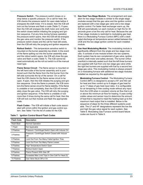
351579-YTS-B-0608Pressure Switch - The pressure switch closes on adrop below a specific pressure. On a call for heat, theICB checks the pressure switch for open state before itenergizes the draft mo<strong>to</strong>r. If it is closed, then the ICB willlock out the furnace and flash a code (Table 7). If open,then the ICB will energize the draft mo<strong>to</strong>r and verify thatthe switch closes before initiating the purging and ignitionsequence. If at any time during furnace operationthe pressure switch opens, then the ICB will de-energizethe gas valve and moni<strong>to</strong>r the pressure switch. If thepressure switch closes and the call for heat still exists,then the ICB will retry the purging and ignition sequence.Rollout Switch - This temperature sensitive switch ismounted on the burner assembly <strong>to</strong>p shield. In the even<strong>to</strong>f the flame spilling out in<strong>to</strong> the burner assembly areaand the rollout switch opens, the ICB will close the gasvalve and flash a code (Table 7). The ICB cannot bereset au<strong>to</strong>matically as the roll out switch is of the manualreset type.Flame Sense Circuit - The flame sensor is mounted onthe left hand side of the burner assembly and is positionedsuch that the flame from the first burner from theleft side surrounds the tip of the sensor. On a call forheat the ICB checks for the flame sense circuit <strong>to</strong> beopen. If open, then the ICB initiates the purging and ignitionsequence. Once the flame is present, the ICB moni<strong>to</strong>rsthe flame sense circuit for flame stability. If the flameis unstable or lost completely, then the ICB will immediatelyclose the gas valve. The ICB will retry the purgingand ignition sequence. If the flame is unstable or lostmore than 5 times during the same call for heat, then theICB will lock out that module and flash the appropriatecode.Flash Codes - The ICB will initiate a flash code associatedwith errors within the ignition and gas control system.See Table 7 for the list of codes for the ICB.Table 7: Ignition Control Board Flash Codes12. Gas Heat Two-Stage Module: The arrangement and operationfor two stage modules is similar <strong>to</strong> the single stagemodules except that the gas valve and the ignition controlare replaced with a two stage gas valve and a two stageignition control. For faster heat exchanger warm up, theICB will au<strong>to</strong>matically run each module on high fire for 30seconds given a low fire only call for heat. Because the useof two stage modules is restricted <strong>to</strong> modulating gas heat,there is a Modulating Furnace Control (MFC) with a dedicateddischarge air temperature sensor added between theUCB and the two stage ignition control for each installedmodule.13. Gas Heat Modulating Module: The modulating module issignificantly different from the single and two stage modules.It consists of one module broken in<strong>to</strong> two systems.Each system has its own complement of gas valve, ignitioncontrol, draft mo<strong>to</strong>r and safety devices. The burner orificemanifold is internally sealed such that the left three burnersare supplied with fuel from one two stage gas valve whilethe right two burners are supplied with fuel by a second twostage gas valve. This modulating module is always presen<strong>to</strong>n a modulating furnace with additional two stage modulesinstalled as required by the application.Modulating Furnace Control - The Modulating FurnaceControl (MFC) is designed <strong>to</strong> accept a W1 and W2 callfor heat and then control up <strong>to</strong> 8 stages of gas heat forup <strong>to</strong> 17 steps of gas heat input rates. It is configurablefor air tempering in free cooling mode without any inputfrom the UCB when in constant volume air flow that is a<strong>to</strong>r above the minimum air flow for heating. It uses configurablevalues and sensor input <strong>to</strong> determine the amoun<strong>to</strong>f heat that is required <strong>to</strong> meet the heating load up <strong>to</strong> themaximum heat output that is installed. Below is thesequence of steps for the three different systems available.The LF and HF designations represent the low fireand high fire gas valve signal for each system, SeeTable 8. Modulating Gas Furnace control board failurecodes are found in Table 9.Flash CodeDescriptionHeart Beat Normal Operation1 Flash Not Applicable2 Flashes Pressure / Centrifugal Switch Open with Inducer On3 FlashesPressure / Centrifugal Switch Closed with InducerOff4 Flashes Lock Out From Too Many Failed Ignition Tries5 Flashes Lock Out From Too Many Flame Losses6 Flashes High Temperature Switch Open7 Flashes Rollout Switch Open8 Flashes Flame Present With Gas Off9 Flashes Exceeded Max Limit Trips In One Call For Heat (5)10 Flashes Gas Valve Stuck Off or OnJohnson Controls Unitary Products 23