analog to digital converter . . . . . . . . . . . . . . . 4 - UPGNet
analog to digital converter . . . . . . . . . . . . . . . 4 - UPGNet
analog to digital converter . . . . . . . . . . . . . . . 4 - UPGNet

You also want an ePaper? Increase the reach of your titles
YUMPU automatically turns print PDFs into web optimized ePapers that Google loves.
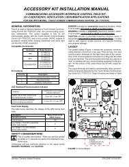
351579-YTS-B-0608Single Enthalpy: the control will consider, along withoutside temperature, outside air humidity [OAH sensor;parameter must be set <strong>to</strong> ON] in enabling free cooling.The outside air enthalpy setpoint parameter [BTU perpound] must also be set.NOTE:For smoke purge, etc., special connections: for standardcontrols, consult a controls specialist familiar withyour local codes.Dual Enthalpy (Comparative/Differential Enthalpy):Both the Outdoor Air Enthalpy and the Return AirEnthalpy [RAH sensor, option parameter must be set <strong>to</strong>ON] are connected <strong>to</strong> the control. The setpoint when theoutdoor air enthalpy is less than the return air enthalpy,free cooling is available. The rules in the control will lockout free cooling and force mechanical cooling when theoutside air temperature exceeds setpoints.19. Power Exhaust Option with Modulating Dampers: Thepower exhaust controls are enabled in Occupied mode. Thebuilding pressure sensor [BSP] provides a signal <strong>to</strong> the control.The exhaust dampers are modulated by a 2-10VDC signalfrom the control, proportional <strong>to</strong> the pressure sensed, <strong>to</strong>the damper actua<strong>to</strong>r. When the actua<strong>to</strong>r opens the dampermore than the parameter “Exhaust Damper Position forExhaust Fan <strong>to</strong> Turn ON” setting, the Simplicity ® controlpowers the 10M starter <strong>to</strong> engage the power exhaust fanmo<strong>to</strong>r. When the dampers reach the ”Exhaust Damper Positionfor Exhaust Fan <strong>to</strong> Turn OFF” setting, the control turnsthe mo<strong>to</strong>r off. When the power exhaust is disabled, the controlcloses the exhaust dampers.20. Non-Modulating Power Exhaust Option: The powerexhaust controls are enabled by the Simplicity ® control.The control powers the exhaust fan mo<strong>to</strong>r by moni<strong>to</strong>ringthe position of the economizer damper vanes [“EconomizerDamper Setting for Exhaust Fan <strong>to</strong> Turn ON [OFF]”]. Theoutlet pressure of the power exhaust fan forces the barometricrelief dampers open. Exhaust Fan operation is continueduntil the economizer reaches the % set in theparameter Gravity closes the barometric relief damperswhen the exhaust fans are off.21. Power Exhaust Option with Variable Frequency Drive(VFD): The power exhaust controls are enabled throughthe Simplicity ® control. The variable frequency drive is controlledby a signal from the control, based on the BuildingPressure sensor (BPS), located in the control box, whichtranslates the building pressure signal <strong>to</strong> a VDC signal.Fine tuning is accomplished by setting parameters in theVFD [ref: separate instruction].NOTE:Modulated exhaust: Pressure-tap tubing must be runfrom an appropriate location in the building <strong>to</strong> the"high" port on the BPS transducer. Dampers on theVFD power exhaust are gravity-closed and are notmodulated. The BPS signal is proportional with the differencebetween outside ambient pressure and buildingpressure. The VFD is set for a minimum speed of33% and a maximum of 100%. The VFD parametersare fac<strong>to</strong>ry set, specific for each control system, andare detailed on a sticker by the drive. The drive manualis shipped with the unit.HEAD PRESSURE CONTROL, R22 (R410A)DESCRIPTIONThe head pressure control option controls the speed ofcondenser fan 1 for low ambient mechanical cooling operationof systems 1 and 2. This option functions independently of theSimplicity® control.The option includes two pressure transducers and a variablefrequency drive. The pressure transducers are connected <strong>to</strong> thedischarge line of system 1 and 2. The VFD modulates <strong>to</strong> thehigher signal; if either system 1 or 2 exceeds 280 psi R22 (360psi for R410a), a secondary mechanical switch close <strong>to</strong> turn onfan 2. Typically the modulated fan will slow down; if bothsystems drop below 180 psi, fan 2 drops out.System 3 on a 30 <strong>to</strong>n R22 and system 3 and 4 on a 40 <strong>to</strong>n R22(and all R410a units) are locked out below 45°F ambient.NOTE:All power exhaust options require that the cus<strong>to</strong>merprovide tubing connections <strong>to</strong> the transducer from arepresentative location in the building; modulatingvaneand VFD exhausts will open full / power on inPurge mode.Altering the fac<strong>to</strong>ry settings could result in poor controlor operation of the system.No special mo<strong>to</strong>r is required on three-phase systems; singlephase systems will use three phase mo<strong>to</strong>rs on fan 1. TheVariable Frequency Drive is pre programmed at the fac<strong>to</strong>ry.SEQUENCE OF OPERATION - FOR HEAD PRESSURECONTROLA call for the first stage cooling powers the 6M contac<strong>to</strong>renergizing the variable frequency drive. The drive will ramp <strong>to</strong>the pre programmed minimum speed of 20 Hertz immediatelyupon start up. As the discharge pressure on system 1 or 2compressor rises, the transducer output signal <strong>to</strong> the variablefrequency drive rises. The drive will increase the speed ofcondenser 1 fan, maintaining a setpoint of 240 psi R22 (325 psiR410a).The scroll compressor produces a rapid rise in dischargepressure upon start up. This usually will result in full speedoperation of condenser fan 1. After the discharge pressure hassettled out, the speed of condenser 1 may decrease especiallyduring times when the ambient temperature is below 80 °F. Afterthe 1 system has stabilized and compressor 2 is energized, thespeed of condenser Fan 1 will increase <strong>to</strong> compensate for thedischarge pressure rise. Typically, since fan 2 will run at fullspeed, fan 1 will slow down when fan 2 energizes.26 Johnson Controls Unitary Products