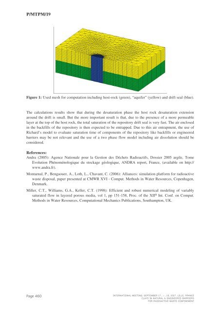
P/<strong>MTPM</strong>/19Figure 1: Used mesh for computation including host-rock (green), “aquifer” (yellow) and drift seal (blue).The calculations results show that during the desaturation phase the host rock desaturation extensionaround the drift is small. But the more important result is that, due to the presence of a more permeablelayer at the top of the host rock, the total saturation of the repository drift seal is very fast. The air enclosedin the backfills of the repository is then expected to be entrapped. Due to this air entrapment, the use ofRichard’s model to evaluate saturation time of components of the repository like backfills or engineeredbarriers may be not relevant and the use of a two phase flow model including air dissolution should beconsidered.References:<strong>Andra</strong> (2005): Agence Nationale pour la Gestion des Déchets Radioactifs, Dossier 2005 argile, TomeEvolution Phénoménologique du stockage géologique, ANDRA report, France, (available on http://www.andra.fr).Montarnal, P., Bengaouer, A., Loth, L., Chavant, C. (2006): Alliances: simulation platform for radioactivewaste disposal, paper presented at CMWR XVI - Comput. Methods in Water Resources, Copenhagen,Denmark.Miller, C.T., Williams, G.A., Keller, C.T. (1998): Efficient and robust numerical modeling of variablysaturated flow in layered porous media, vol 1, pp 151-158, Proc. of the XII th Int. Conf. on Comput.Methods in Water Resources, Computational Mechanics Publications, Southampton, UK.Page 460INTERNATIONAL MEETING, SEPTEMBER 17...>...18, 2007, LILLE, FRANCECLAYS IN NATURAL & ENGINEERED BARRIERSFOR RADIOACTIVE WASTE CONFINEMENT
P/<strong>MTPM</strong>/20NUMERICAL INTERPRETATIONOF GAS TRANSPORT EXPERIMENTSON WATER-SATURATED SAMPLESOF OPALINUS CLAYA. Poller 1 , G. Mayer 1 , J. Croisé 1 , P. Marschall 2 , B. Krooss 3 , J.M. Matray 4 , T. Tanaka 5 , P. Vogel 61. Colenco Power Engineering AG, Groundwater Protection and Waste Disposal, Täfernstr. 26,CH-5404 Baden- Switzerland ( gerhard.mayer@colenco.ch )2. NAGRA - National Cooperative for the Disposal of Radioactive Waste, Hardstrasse 73,CH 5430 Wettingen, Switzerland ( paul.marschall@nagra.ch )3. Institute of Geology and Geochemistry of Petroleum and Coal (LEK), Rheinisch-westfälischetechnische Hochschule Aachen, Lochnerstr. 4-20, Haus B, Aachen, krooss@lek.rwth-aachen.de4. IRSN - Institut de Radioprotection et de Sûreté Nucléaire, Av. du Gen. Leclerc BP n°17, 92262Fontenay-aux-roses, France (jean-michel.matray@irsn.fr)5. Obayashi Corporation, Konan 2-15-2, Minato-ku, Tokyo 108-8502, Japan(obayashi@grimsel.com)6. BGR - Bundesanstalt für Geowissenschaften und Rohstoffe, Stilleweg 2, 30655 Hannover,Germany ( p.vogel@bgr.de)INTRODUCTIONThe understanding of gas transport processes through the host rock forms a key issue in the assessment oflong-term safety of radioactive waste repositories in argillaceous formations (Marschall et al., 2005). Thegas transport capacity of such ultra-low permeability rock formations can be tested in the laboratory by gasbreakthrough tests on core samples. A series of gas breakthrough tests using either Helium or Argon onsmall cylindrical samples ( Ø 2.4cm, height ≈ 2cm) of the Opalinus Clay (Mont Terri, Switzerland) has beenconducted by Krooss and Alles, 2006. The experimental data and conditions were carefully reviewed andan interpretation was performed taking into account both two-phase flow (water and gas) and diffusivetransport of gas in the aqueous phase by means of numerical simulations.EXPERIMENTAL DATA, ANALYSIS METHOD AND RESULTSA schematic of the triaxial flow cell is presented in Figure 1. The sample is confined with an axial andradial confining pressure of 6 MPa. A water permeability test is performed on each sample prior to the gastest. At the beginning of the gas test an air-filled volume is created at the downstream end of the sampleby withdrawing a definite volume of water using a syringe. Gas (He or Ar) is then injected at high pressureinto the upstream compartment (tubing + porous disc) and closed. The pressure evolution in the twocompartments is continuously monitored over time: A steady decrease is observed in the upstreamcompartment, a steady increase at the downstream compartment, respectively. This type of experimentalset-up has been thoroughly tested and has also been used by Hildenbrand et al., 2002.The simultaneous acting of different transport processes required adopting a stepwise approach for theanalysis of the experiment. The following steps were performed: i) A model identification step based onTOUGH2 simulations (a two-phase flow and transport code, Pruess et al., 1999) in order to investigate theeffects of the different transport processes on the pressure evolutions in the upstream and downstreamcompartments. ii) A sensitivity analysis on two-phase flow and diffusion parameters of the samples andon initial and boundary conditions using iTOUGH2. iii) A parameter estimation step by inverse modellingusing iTOUGH2.The prevailing processes influencing the measured pressure evolution have been identified and quantified.These are: Storage of gas and water in the upstream and downstream compartments, advective transportINTERNATIONAL MEETING, SEPTEMBER 17...>...18, 2007, LILLE, FRANCECLAYS IN NATURAL & ENGINEERED BARRIERSFOR RADIOACTIVE WASTE CONFINEMENTPage 461