Autotrol Performa Valve - Pentair Residential Filtration
Autotrol Performa Valve - Pentair Residential Filtration
Autotrol Performa Valve - Pentair Residential Filtration

You also want an ePaper? Increase the reach of your titles
YUMPU automatically turns print PDFs into web optimized ePapers that Google loves.
® <strong>Autotrol</strong> <strong>Performa</strong> <strong>Valve</strong>With 400 Series ControlWater Conditioning Control SystemDealer Installation, Operation and Maintenance Manual
Table of ContentsInstallation . . . . . . . . . . . . . . . . . . . . . . . . . . . . . . . . 3Location SelectionWater Line ConnectionDrain Line ConnectionBrine LineOverflow Line ConnectionPlacing Conditioner into Operation . . . . . . . . . . . . . 5Electrical Connection400 Series Control Settings . . . . . . . . . . . . . . . . . . . 6440i (obsolete)Programming460iProgrammingTime of Day SettingHardness SettingCapacity SettingCalendar Override Setting460TCProgrammingTime of Day SettingDay SettingClock SettingCommon Features . . . . . . . . . . . . . . . . . . . . . . . . . . 9Salt Dial AdjustmentGuest CycleManual RegenerationRemoving the <strong>Valve</strong> Assembly for Servicing . . . . . 11Removing 440i or 460i/460TC for Servicing . . . . . 11Preventive Maintenance . . . . . . . . . . . . . . . . . . . . 12Injector Screw and InjectorWater MeterSpecifications. . . . . . . . . . . . . . . . . . . . . . . . . . . . . 13Pressure Graphs . . . . . . . . . . . . . . . . . . . . . . . . . . 14Identification of Control Valving . . . . . . . . . . . . . . . 15<strong>Valve</strong> Disc Principle of Operation. . . . . . . . . . . . . . 15Flow Diagrams. . . . . . . . . . . . . . . . . . . . . . . . . . . . 15Replacement Parts . . . . . . . . . . . . . . . . . . . . . . . . 17Troubleshooting . . . . . . . . . . . . . . . . . . . . . . . . . . . 20Disinfection of Water Conditioners. . . . . . . . . . . . . 232
InstallationAll plumbing and electrical connections must conform tolocal codes.Inspect unit carefully for carrier shortage or shippingdamage.The 268 water conditioner’s controlvalve conforms to NSF/ANSI 44 and 61for materials and structural integrityonly. Generic systems were tested andcertified by WQA as verified by theperformance data sheet.Location Selection1. The distance between the unit and a drain should beas short as possible.2. If it is likely that supplementary water treatmentequipment will be required, make certain adequateadditional space is available.3. Since salt must be added periodically to the brinetank, the location should be easily accessible.4. Do not install any unit closer to a water heater thana total run of 10 feet (3 m) of piping between theoutlet of the conditioner and the inlet to the heater.Water heaters can sometimes overheat to theextent they will transmit heat back down the coldpipe into the unit control valve.Hot water can severely damage the conditioner. A10-foot (3-m) total pipe run, including bends,elbows, etc., is a reasonable distance to helpprevent this possibility. A positive way to preventhot water flowing from heat source to theconditioner, in the event of a negative pressuresituation, is to install a check valve in the soft waterpiping from the conditioner. If a check valve isinstalled, make certain the water heating unit isequipped with a properly rated temperature andpressure safety relief valve. Also, be certainthat local codes are not violated.5. Do not locate unit where it or its connections(including the drain and overflow lines) will ever besubjected to room temperatures under 34 o F (1 o C)or over 120 o F (49 o C).6. Do not install unit near acid or acid fumes.7. The use of resin cleaners in an unvented enclosureis not recommended.Water Line ConnectionThe installation of a bypass valve system isrecommended to provide for occasions when the waterconditioner must be bypassed for hard water or forservicing.The most common bypass systems are the <strong>Autotrol</strong>UNDERTESTED AND CERTIFIEDINDUSTRYSTANDARDSSeries 1265 bypass valve (Figure 1) and plumbed-inglobe valves (Figure 2). Though both are similar infunction, the <strong>Autotrol</strong> Series 1265 bypass offerssimplicity and ease of operation.B Y PA S SNot in BypassInOutFigure 1 - <strong>Autotrol</strong> Series 1265 Bypass <strong>Valve</strong>WaterWaterFigure 2 - Typical Globe <strong>Valve</strong> Bypass SystemDrain Line ConnectionB Y PA S SWaterConditionerNot in BypassWaterConditionerIn BypassNote: Standard commercial practices are expressedhere. Local codes may require changes to the followingsuggestions.1. Ideally located, the unit will be above and not morethan 20 feet (6.1 m) from the drain. For suchinstallations, using an appropriate adapter fitting,connect 1/2-inch (1.3-cm) plastic tubing to the drainline connection of the control valve.2. If the backwash flow rate exceeds 5 gpm(22.7 Lpm) or if the unit is located more than 20 feet(6.1 m) from drain, use 3/4-inch (1.9-cm) tubing forruns up to 40 feet (12.2 m). Also, purchaseappropriate fitting to connect the 3/4-inch tubing tothe 3/4-inch NPT drain connection.InB Y PA S SWaterConditionerIn BypassWaterConditionerOutB Y PA S S3
3. If the unit is located where the drain line must beelevated, you may elevate the line up to 6 feet(1.8 m) providing the run does not exceed15 feet (4.6 m) and water pressure at conditioner isnot less than 40 psi (2.76 bar). You may elevate anadditional 2 feet (61 cm) for each additional10 psi (0.69 bar).4. Where the drain line is elevated but empties into adrain below the level of the control valve, form a7-inch (18-cm) loop at the far end of the line so thatthe bottom of the loop is level with the drain lineconnection. This will provide an adequate siphontrap.5. Where the drain empties into an overhead sewerline, a sink-type trap must be used.IMPORTANT: Never insert drain line into a drain, sewerline or trap. Always allow an air gap between the drainline and the wastewater to prevent the possibility ofsewage being back-siphoned into the conditioner.Overflow Line ConnectionIn the absence of a safety overflow and in the event ofa malfunction, the BRINE TANK OVERFLOW will direct“overflow” to the drain instead of spilling on the floorwhere it could cause considerable damage. This fittingshould be on the side of the cabinet or brine tank.To connect overflow, locate hole on side of brine tank.Insert overflow fitting (not supplied) into tank and tightenwith plastic thumb nut and gasket as shown (Figure 4).Attach length of 1/2-inch (1.3-cm) I.D. tubing (notsupplied) to fitting and run to drain. Do not elevateoverflow line higher than 3 inches (7.6 cm) belowbottom of overflow fitting. Do not tie into drain line ofcontrol unit. Overflow line must be a direct, separate linefrom overflow fitting to drain, sewer or tub. Allow an airgap as per drain line instructions (Figure 3).Right WayBrine TankOverflow FittingInstalledFigure 3Note: Standard commercial practices have beenexpressed here. Local codes may require changes tothese suggestions.Brine Line ConnectionIt will be necessary to install the brine line to the brinefitting on the valve (3/8-inch NPT).Be sure all fittings and connections are tight.Connect 1/2-inch (1.3-cm)Tubing or Hose and Runto DrainFigure 44
Placing Conditioner into OperationAfter all previous steps have been completed, the unit isready to be placed into operation. Follow these stepscarefully.1. Remove control valve cover by first releasing theplastic clip from the back of the cover. Pull back ofcover slightly outward and lift up.Note: The following steps will require turning theindicator knob (Figure 5 and Figure 6) to variouspositions. Manually rotate the camshaftCOUNTERCLOCKWISE only until indicator knobpoints to desired position. (See manualregeneration sections for each control’s manualoperation.)2. Rotate indicator knob COUNTERCLOCKWISEuntil it points directly to the word BACKWASH.3. Fill media tank with water.A. With water supply off, place the bypass valve(s)into the “not in bypass” position.B. Open water supply valve very slowly toapproximately the 1/4 open position.IMPORTANT: If opened too rapidly or too far, mediamay be lost. In the 1/4 open position, you should hearair escaping slowly from the drain line.C. When all of the air has been purged from thetank (water begins to flow steadily from thedrain), open the main supply valve all the way.D. Allow water to run to drain until clear.E. Turn off water supply and let the unit stand forabout five minutes. This will allow all trapped airto escape from the tank.4. Add water to brine tank (initial fill).With a bucket or hose, add approximately4 gallons (15 liters) of water to brine tank. If thetank has a salt platform above the bottom of thetank, add water until the level is approximately1 inch (25 mm) above the platform.5. Place the conditioner into operation.A. With the water supply valve completely open,carefully advance the indicator knobCOUNTERCLOCKWISE to the center of theBRINE REFILL position. Hold at this positionuntil water starts to flow through the brine lineinto the brine tank. Do not run for more than oneor two minutes.B. Advance the indicator knobCOUNTERCLOCKWISE until it points to thecenter of the BRINE/SLOW RINSE position.C. With the conditioner in this position, check tosee if water is being drawn from the brine tank.The water level in the brine tank will recede veryslowly. Observe water level for at least threeminutes. If the water level does not recede, or ifit goes up, reference the Troubleshootingsection.D. Advance the indicator knobCOUNTERCLOCKWISE to the SERVICEposition and run water from a nearby faucet untilthe water is clear and soft.Electrical Connection100 VAC, 115 VAC, and 230 VAC units: Remove twisttie from the power cord and extend cord to its full length.Make sure power source matches the rating printed onthe control. Be certain a wall switch does not control theoutlet.12 VAC: Connect the plug of the transformer (supplied)secondary cable to the mating socket at the rear orbottom of the timer housing. Be certain the transformeris secure and is plugged into a power source of correctvoltage that is not controlled by a wall switch.5
400 Series Control Settings440i Control (obsolete)Day Arrow Skipper Pins Skipper Wheel460i ControlWater Flow IndicatorPM IndicatorHour Time DisplayAccess DoorRaisedTabIndicator KnobTimerLocking PinTime ArrowTimer KnobIndicator KnobTimerLocking PinTime Set ButtonTransformer PlugReceptacleJumperSpareJumperFigure 5Figure 6Programming1. Set days of regeneration on skipper wheel (Figure 5).• Pull all skipper pins outward (away fromcontrol).• Rotate skipper wheel until day arrow points tocurrent day or number 1.• Depress skipper pin(s) at day(s) for whichregeneration is desired.2. Set the time of day.• Grasp timer knob and pull outward.• Rotate in either direction until the timer arrowpoints to the actual time of day.• Release timer knob.Note: With the time of day properly set, the conditionerwill regenerate at about 2:30 a.m. If you prefer to havethe unit regenerate at an earlier or later time, simply setcurrent time-of-day accordingly (e.g., to have the unitregenerate at 4:30 a.m.—two hours later—set the clocktwo hours earlier than the actual time of day.)Note: The Timer Locking Pin should always behorizontal (Figure 5) during operation.ProgrammingPlug the wall-mount transformer into a functioningelectrical outlet that is not controlled by a switch. Plugthe transformer into the transformer plug receptacle onthe control.Open the access door by pushing the raised tab on thedoor toward the left while pulling the tab out (Figure 6).Time of Day SettingWith the jumper on the set of pins next to the word TIME(Figure 7), set the time of day to the closest hour bypressing the black TIME SET button. PM hours areindicated by a light next to the letters PM on the displaywindow.Note: The use of a small needle-nose pliers will aid inmoving the jumper.Note: The unit is factory set to regenerate at 2:00 a.m.If you prefer to have the unit regenerate at an earlier orlater time, simply set the current time of day accordingly(e.g., to have the unit regenerate at4:00 a.m.—two hours later—set the clock two hoursearlier than the actual time of day).Note: The Timer Locking Pin should always behorizontal (Figure 6) during operation.6
Hardness SettingMove the jumper to the set of pins next to the wordHARDNESS (Figure 8). Press the black TIME SETbutton until the hardness of the incoming water supplyis displayed. The hardness range is from 1 to 99 grainsper gallon.To change water hardness stated in parts per million(PPM) to grains per gallon (GPG) use this formula:Parts per Million17.1= Grains per Gallon7. The calendar override program is maintainedduring power outages by the NOVRAM circuitry.8. To remove the calendar override, follow the samesteps above and program back to “0.”460TC ControlPM IndicatorHour Time DisplayAccess Door460TCDAYSCLOCKRaisedTabFigure 7 Figure 8 Figure 9Capacity SettingMove the jumper to the set of pins next to the wordCAPACITY (Figure 9). Press the black TIME SETbutton until the correct capacity value is displayed. Thecapacity range is 1 to 99 kilograins. Refer to theSuggested Salt Dial Settings table (9).Return the jumper to the top set of pins next to the wordTIME and replace the access door. The jumper mustNOT be left on any pins other than the top pair nextto the word TIME. Otherwise, the unit may show ablank display.Note: A spare jumper is located on the bottom set ofpins.In the event that the hardness or capacity setting mustbe changed, simply follow the appropriate stepsdescribed above.Calendar Override Setting1. Disconnect power.2. Place jumper on Pin A and reconnect power.3. Move jumper to Pin B. A zero will appear, indicatingzero days of calendar override. All 460i controllersare preprogrammed in this manner at themanufacturer.4. Depress the black TIME SET button. The numberswill roll from “0” to “15.” Release the switch at thedesired number of days for the calendar override.For example, releasing the switch at “10” wouldprogram a 10-day calendar override.5. Disconnect power.6. Place jumper back on TIME and reconnect power.Indicator KnobTimerLocking PinProgrammingTime Set ButtonFigure 10Plug the wall-mount transformer into a functioningelectrical outlet that is not controlled by a switch. Plugthe transformer into the transformer plug receptacle onthe control.Open the access door by pushing the raised tab on thedoor toward the left while pulling the tab out (Figure 10).Time of Day SettingTransformer PlugReceptacleJumperSpareJumperWith the jumper on the set of pins next to the word TIME(Figure 11), set the time of day to the closest hour bypressing the black TIME SET button. PM hours areindicated by a light next to the letters PM on the displaywindow.Note: The use of a small needle-nose pliers will aid inmoving the jumper.Note: The unit is factory set to regenerate at 2:00 a.m.If you prefer to have the unit regenerate at an earlier orlater time, simply set the current time of day accordingly(e.g., to have the unit regenerate at4:00 a.m.—two hours later—set the clock two hoursearlier than the actual time of day).Note: The Timer Locking Pin should always behorizontal (Figure 10) during operation.7
Days SettingMove the jumper to the set of pins next to the wordDAYS (Figure 12). Press the black TIME SET buttonuntil the desired number of days between regenerationis displayed. The range is from 1 to 30 days.TIMEDAYSCLOCKTIMEDAYSCLOCKTIMEDAYSCLOCKFigure 11 Figure 12 Figure 13Clock SettingMove the jumper to the set of pins next to the wordCLOCK (Figure 13). Press the black TIME SET buttonuntil the desired clock setting is displayed. The clockrange is 0 or 1. Select 0 for the standard AM/PM clockor select 1 for a 24 hour clock.Return the jumper to the top set of pins next to the wordTIME and replace the access door. The jumper mustNOT be left on any pins other than the top pair nextto the word TIME. Otherwise, the unit may show ablank display.Note: A spare jumper is located on the bottom set ofpins.8
Common FeaturesWhen using the <strong>Performa</strong> valve with the 440i or 460icontrols, there are several features and procedures thatare unique to the 400 series controls. They are asfollows:Salt Dial AdjustmentThese models may be adjusted to produce maximum tominimum conditioning capacities by setting the salt dial,which controls the amount of salt used perregeneration. When desired, the minimum setting maybe used on installations if the frequency of regenerationis increased to compensate for lower regeneratedconditioning capacity. The installing dealer will set theunit for proper salt usage. Further adjustments areneeded only if the hardness of the water supplychanges or if water use changes dramatically. Capacitywill need to be adjusted accordingly.To adjust salt dosage, insert a small screwdriver into thewhite indicator knob and move pointer to proper saltsetting (Figure 14).Note: To convert the salt settings from English to metric,divide by 2.2 (e.g., 12 pounds 2.2 = 5.5 kg of salt).CapacitySetting(Kilograins)Figure 14Table 1 – Suggested Salt Dial Settings (Pounds of Salt) For Various Size SoftenersIndicator Knob0.5 Ft 3 0.75 Ft 3 1.0 Ft 3 1.25 Ft 3 1.5 Ft 3 1.75 Ft 3 2.0 Ft 3 2.5 Ft 312 4.5 — — — — — — —16 9.0 5.5 — — — — — —20 — 8.5 6.0 — — — —24 — 14.0 8.5 7.0 — — — —30 — — 15.0 11.0 9.0 — — —32 — — 18.5 12.5 10.0 9.0 — —35 — — — 16.0 12.0 10.0 9.0 —40 — — — 23.0 1 17.0 14.0 12.0 —48 — — — — 28.0 1 21.0 1 17.0 14.060 — — — — — — 30.0 1 21.0 11 When using the 440i or 460i you must use Extra Salt cam and divide the suggested setting by 2 to accomplish these settings.The amount of salt placed in the brine tank has nothingto do with the amount of salt used during theregeneration cycle. Water will dissolve and absorb saltonly until it becomes saturated. A given amount of brine(salt-saturated water) contains a specific amount of salt.The salt dial controls the amount of brine used duringthe regeneration cycle (e.g., when set at15 pounds (6.8 kg) the amount of brine the conditionerwill use for each regeneration will contain 15 pounds(6.8 kg) of salt, etc.)Never let the amount of salt in the brine tank be lowerthan the normal liquid level. Do not overload the brinetank with salt.9
Guest CycleWhen abnormally high water usage exhausts yourwater conditioner’s capacity ahead of schedule, anextra regeneration can be achieved. Depress theindicator knob on the 440i (Figure 5) with a wide-bladescrewdriver and turn COUNTERCLOCKWISE toSTART to initiate a regeneration. For the 460i, simplydepress the indicator knob (Figure 6). It will take a fewminutes for regeneration to start. A normal regenerationwill take approximately two hours.Manual RegenerationElectricity is used only to run the control and to rotatethe camshaft. All other functions are operated by waterpressure. Therefore, in the event of a power outage, allthe regeneration positions may be dialed manually bydepressing the indicator knob and turningCOUNTERCLOCKWISE (Figure 5 and Figure 6). Thefollowing cycle times should be used for properregeneration:BACKWASH—14 minutesBRINE/SLOW RINSE—52 minutesFAST RINSE/REFILL—10 minutesPURGE—6 minutesDo not exceed 10 minutes for the FAST RINSE/REFILLcycle as this will cause excessive salt usage during thenext regeneration and possibly a salt residue in thesoftened water.10
Removing the <strong>Valve</strong> Assembly for Servicing1. Unplug the power cord.2. Shut off water supply or put bypass valve(s) intobypass position.3. Remove cover and with screwdriver, relieve tankpressure by pushing open valve No. 7 (rear flapper)on control as shown (Figure 11).Lever DownFigure 12Lever UpFigure 114. When used with a globe valve bypass, loosen anddetach the inlet, outlet, brine and drain lines fromthe valve. If using the 1265 bypass, loosen andremove valve from bypass as well as loosening andremoving the brine and drain lines.5. Unscrew valve (counterclockwise) and removevalve from tank.6. To replace the control valve, reverse the aboveprocedure.Cam Pulled OutFigure 13Removing 440i or 460i/460TC for Servicing1. Unplug the power cord.2. Remove cover.3. The control should be in service position(Figure 12).4. Rotate the locking lever to point up (Figure 13).5. Pull the end of the camshaft out from the lever andremove the camshaft.6. Remove the timer locking pin and lift the controlstraight up and off of the valve.7. To reinstall the camshaft and control, reverse theabove procedures.NOTE: When reinstalling the camshaft the controlshould be in SERVICE position. When the camshaft ispositioned, cams will make contact with valves to forcethem open.11
Preventive MaintenanceInjector Screen and InjectorInspect and clean brine tank and screen filter on end ofbrine pickup tube once a year or when sedimentappears in the bottom of the brine tank.Clean injector screen and injector once a year:1. Unplug the wall-mount transformer.2. Shut off water supply or put bypass valve(s) intobypass position.3. Relieve system pressure by opening valve No. 7(at rear) with a screwdriver (Figure 11).4. Using a screwdriver, remove injector screen andinjector cap (Figure 14).5. Clean screen using a fine brush. Flush until clean.6. Using a needle-nose pliers, pull injector straight out.7. Flush water into the injector screen recess of thevalve body to flush debris out through the injectorrecess.8. Clean and flush the injector.9. Lubricate the O-rings on the injector, injector capand injector screen with silicone lubricant only!10. Reinstall the injector, injector cap and injectorscreen.IMPORTANT: Do not overtighten the plastic cap. Seatthe cap lightly into position. Overtightening may causebreakage of the plastic cap that may not be immediatelyevident.11. Plug the wall-mount transformer into outlet; resetclock if necessary.12. Slowly open water supply valve or return bypassvalve(s) to the “service” position.Injector ScreenTurbineWater Meter MaintenanceNote: A water meter is used only with the 460i control.If you are using the 440i or 460TC control, this sectiondoes not pertain to your conditioner.The metering device used with the 460i demand controlmay require simple maintenance. In rare instances, theturbine wheel of the water meter can collect smallparticles of oxidized iron, eventually preventing thewheel from turning.1. Shut off the water supply or put the bypass valve(s)into the bypass position.2. Relieve pressure by opening the Backwash Drain<strong>Valve</strong> (the seventh back from the control) with ascrewdriver (Figure 11).3. Loosen and remove the pipe/tube adapters or 1265bypass from the inlet and outlet of the valve body.4. Using a needle-nose pliers, remove the turbinefrom the outlet housing. Grasp one of the four vanesof the outer gland and pull straight out to removeturbine assembly from the outlet of the valve(Figure 14).5. Carefully remove the turbine wheel from thehousing. Use a toothbrush to lightly scrub the ironoff the magnet. Iron buildup on the surfaces can beremoved by soaking the wheel in a mild sodiumhydrosulfite (such as RoVer 1 ) solution for a fewminutes. Flush thoroughly with water.6. Carefully reinstall the turbine wheel into the turbinecage housing. Make sure that the shaft of the wheelseats into the bearing of the cage. Reassemble theturbine cage and check that the wheel rotatesfreely.7. Reinstall the turbine cage into the outlet of thevalve.8. Reinstall the pipe/tube adapters or 1265 bypass tothe inlet and outlet of the valve.9. Turn on the water supply or put the bypass valve(s)into the service position and purge the air out of thesystem.To check for proper meter operation, open adownstream faucet and observe the water flowindication on the control display.InjectorCapFigure 141. RoVer is a trademark of Hach Chemical Company.12
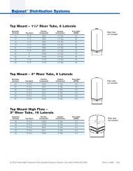
DAYSCLOCKSpecifications460TCHydrostatic Test Pressure . . . . . . . . . . . . . . . . . . . . . . . . . . . . . . . . . . . . . . . . . . . . . . . . . . . . . . . . 300 psi (20.69 bar)Working Pressure . . . . . . . . . . . . . . . . . . . . . . . . . . . . . . . . . . . . . . . . . . . . . . . . . . . . . . . 20-125 psi (1.38 - 8.62 bar)Standard Electrical Rating . . . . . . . . . . . . . . . . . . . . . . . . . . . . . . . . . . . . . . . . . . . . . . . . . . . . . . . . . . . . . . 115V 60 HzOptional Electrical Rating . . . . . . . . . . . . . . . . . . . . . . 115V 50 Hz, 230V 50 Hz, 200V 60 Hz, 24V 60 Hz, 24V 50 Hz,. . . . . . . . . . . . . . . . . . . . . . . . . . . . . . . . . . 100V 60 Hz, 100V 50 Hz, 12V 50 Hz/transformer, 12V 60 Hz/transformerElectrical Cord (standard rating) . . . . . . . . . . . . . . . . . . . . . . . . . . . . . . . . . . . . . . . . . 60 inch (1.5 m) 3-wire with plugPressure Tank Thread . . . . . . . . . . . . . . . . . . . . . . . . . . . . . . . . . . . . . . . . . . . . . . . . . . . . . . . . . . . . .2 1/2 inch-8 maleRiser Pipe Diameter Required. . . . . . . . . . . . . . . . . . . . . . . . . . . . . . . . . . . . . . . . . . . . . . . . 1.050 inch OD (26.7 mm)Riser Pipe Length . . . . . . . . . . . . . . . . . . . . . . . . . . . 1-1/8 ±1/8 inches (31.8 mm) higher than the top of mineral tankStandard Connection . . . . . . . . . . . . . . . . . . . . . . . . . . . . . . . . . . . . . . . . . . . . 1-inch (25.4-mm) copper tube adaptersOptional Connections . . . . . . . . . . . . . . . . . . . . . . . . . . . . . . . . . .3/4-inch, 22-mm, and 28-mm copper tube adapters3/4-inch BSPT, 1-inch BSPT, 1-inch NPT stainless steel pipe adapters3/4-inch, 1-inch, 25-mm CPVC tube adaptersBrine Line Connection . . . . . . . . . . . . . . . . . . . . . . . . . . . . . . . . . . . . . . . . . . . . . . . . . . . . . . . . . . . 3/8-inch NPT maleDrain Line Connection . . . . . . . . . . . . . . . . . . . . . . . . . . . . . . . . . . . . . . . . . . . . . . . . . . . . . . . . . . . 3/4-inch NPT maleOptional Bypass <strong>Valve</strong>. . . . . . . . . . . . . . . . . . . . . . . . . . . . . . . .Rotating handles, full 1-inch porting, reinforced plasticControl Module, Tank Adapter . . . . . . . . . . . . . . . . . . . . . . . . . . . . . . . . . . . . . . . . . . . . . . . . . . . . . . Reinforced plasticRubber Goods . . . . . . . . . . . . . . . . . . . . . . . . . . . . . . . . . . . . . . . . . . . . . . . . . . . Compounded for cold water serviceProgram Clock (Timer) . . . . . . . 440i: Available in 6- or 7-day English, German, French, Italian, Spanish, Japanese. . . . . . . . . . . . . . . . . . . . . . . . . . . . . . . . . . . . 460i: Available in English, German, French, Italian, Spanish, JapaneseBrine Refill Control. . . . . . . . . . . . . . . . . . . . . . . 1 to 10 lbs (0.45 to 4.5 kg) of salt or 3 to 19 lbs (1.4 to 8.6 kg) of saltInjector Size “A” White. . . . . . . . . . . . . . . . . Nozzle 042-inch (1.1-mm) diameter, Throat .089-inch (2.3-mm) diameterInjector Size “B” Blue. . . . . . . . . . . . . . . . . Nozzle .052-inch (1.3-mm) diameter, Throat .099-inch (2.5-mm) diameterInjector Size “C” Red . . . . . . . . . . . . . . . . . Nozzle .059-inch (1.5-mm) diameter, Throat .099-inch (2.5-mm) diameterInjector Size "D" Green . . . . . . . . . . . . . . . Nozzle .071-inch (1.8-mm) diameter, Throat .147-inch (3.7-mm) diameterInternal Backwash Controllers. . . . . . . . . . . . . . . . . 7- through 14-inch (17.8- though 35.6-cm) diameter media tanksAll sizes to flow 4.5 gpm/sq ft (183 L/m/m 2 ) of bed area.For tank sizes above 14 inches in diameter, use an external flow control.13
Pressure GraphsInjector #1031363"A" in a 268 <strong>Valve</strong>Injector #1031364"B" in a 268 <strong>Valve</strong>M3/hr0.200.150.100.05GPM1.000.750.500.25TotalRinseBrine DrawM3/hr0.300.250.200.150.100.05GPM1.251.000.750.500.25TotalRinseBrine Draw0.000.0020 40 60 80 100 120PSI0.000.0020 40 60 80 100 120PSI400 600 800 1000 1200 1400 1600 1800bar400 600 800 1000 1200 1400 1600 1800barInjector #1031365"C" in a 268 <strong>Valve</strong>Injector #1030272"D" in a 268 <strong>Valve</strong>M3/hr0.200.150.100.050.00GPM1.751.501.251.000.750.500.250.00TotalRinseBrine Draw20 40 60 80PSI100 120400 600 800 1000 1200 1400 1600 1800barM3/hr0.300.250.200.150.100.050.00GPM2.252.001.751.501.251.000.750.500.250.00TotalRinseBrine Draw20 40 60 80 100 120PSI400 600 800 1000 1200 1400 1600 1800barBackwash Number 7 8 9 10 12 13 14Flow (GPM*) 1.2 1.6 2.0 2.5 3.5 4.1 4.8Flow (LPM*) 4.5 6.0 7.6 9.5 13.2 15.5 18.2*Approximate flow rates at 60 psi (4.14 bar)14
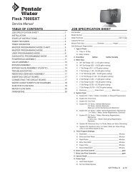
Control <strong>Valve</strong>Identification of Control Valving<strong>Valve</strong> Disc Principle of Operation6 Rinse Drain <strong>Valve</strong>7 Backwash Drain <strong>Valve</strong>s4 Outlet <strong>Valve</strong>2 Bypass <strong>Valve</strong>5 Refill <strong>Valve</strong>1 Brine <strong>Valve</strong>3 Inlet <strong>Valve</strong>Flow Diagrams1 Service PositionHard WaterSoft Water2 Backwash PositionHard WaterSoft WaterInlet231BrineAdjustmentInlet231BrineAdjustment55Outlet46 7Outlet467BackwashFlowControl<strong>Valve</strong>No.1 - Closed2 - Closed3 - Open4 - Open5 - Closed6 - Closed7 - ClosedDrainMineral TankBrine Tank<strong>Valve</strong>No.1 - Closed2 - Open3 - Closed4 - Open5 - Closed6 - Closed7 - OpenDrainMineral TankBrine Tank15
3 Brining/Slow Rinse Position 4 Purge PositionHard WaterHard WaterSoft WaterSoft WaterInlet231BrineAdjustmentInlet231BrineAdjustment55Outlet46 7Outlet467<strong>Valve</strong>No.1 - Open2 - Open3 - Closed4 - Closed5 - Closed6 - Open7 - ClosedDrainMineral TankBrine Tank<strong>Valve</strong>No.1 - Closed2 - Open3 - Open4 - Closed5 - Closed6 - Open7 - ClosedDrainMineral TankBrine Tank5 Brine Refill PositionHard WaterSoft Water1BrineAdjustmentInlet235Outlet46 7<strong>Valve</strong>No.1 - Closed2 - Closed3 - Open4 - Open5 - Open6 - Closed7 - ClosedDrainMineral TankBrine Tank16
14863Replacement Parts<strong>Performa</strong> <strong>Valve</strong>24513131516141093167125819121117
Parts ListPartPartCode No. Description Qty. Code No. Description Qty.1 1035606 <strong>Valve</strong> Assembly, w/o Flow Controls 1 8 Brine Refill Control (440i and 460i): 1(460i, 460TC) 1034261 1 to 10 Pounds Salt2 Camshaft: 1 1034263 3 to 19 Pounds Salt1035625 440i, 460i Standard 9 1002449 Drain Fitting Elbow (3/4” hose barbed) 11035627 440i, 460i Extra Salt ** 10 1000226 Screen/Cap Assembly 13 1031391 Timer Locking Pin 1 11 1010429 O-Ring 14 Drain Control Assembly: 1 12 1035622 Tank Ring 11000209 No. 7 (1.2 gpm; 4.5 Lpm) 13 Plumbing Adapter Kits: 11000210 No. 8 (1.6 gpm; 6.1 Lpm) 1001606 3/4-inch Copper Tube Adapter Kit1000211 No. 9 (2.0 gpm; 7.6 Lpm) 1001670 1-inch Copper Tube Adapter Kit1000212 No. 10 (2.5 gpm; 9.5 Lpm) 1041210 1-1/4-inch Copper Tube Adapter Kit1000213 No. 12 (3.5 gpm; 13.2 Lpm) 1001608 22-mm Copper Tube Adapter Kit1000214 No. 13 (4.1 gpm; 15.5 Lpm) 1001609 28-mm Copper Tube Adapter Kit1000215 No. 14 (4.8 gpm; 18.2 Lpm) 1001613 3/4-inch CPVC Tube Adapter Kit5 1030502 Ball, Flow Control 2 1001614 1-inch CPVC Tube Adapter Kit6 Injector Assembly: 1 1001615 25-mm CPVC Tube Adapter Kit1032970 “A” Injector - White 1001769 3/4-inch NPT Plastic Pipe Adapter Kit1032971 “B” Injector - Blue 1001603 1-inch NPT Plastic Pipe Adapter Kit1032972 “C” Injector - Red 1001604 3/4-inch BSPT Plastic Pipe Adapter Kit1030272 “D” Injector - Green 1001605 1-inch BSPT Plastic Pipe Adapter Kit7 Injector Cap Assembly: 1 3023824 3/4-inch BSPT S.S. Pipe Adapter Kit1000217 “A” Cap 3023828 1-inch NPT S.S. Pipe Adapter Kit1000218 “B” Cap 3023807 1-inch BSPT S.S. Pipe Adapter Kit1000219 “C” Cap 14 1033444 Turbine Assembly (460i only) 11030303 “D” Cap 15 1235339 Spring, one pc 268 1* <strong>Valve</strong> Disc Kit:1041174 Standard1041175 Severe Service* 3019870 I-Lid Cover 116 3019870 Lever, Locking Cam 268* Not Shown** Soft water refill is not available with the extra salt cam18
440i Control460i Control1 2440TC Control1265 Bypass460TCBYPASSDAYSCLOCKBYPASS43PartCode No. Description Qty.1 440i Control (6 day or 7 day) 12 460i Control 13 4001086 460TC Control4 1040930 1265 Bypass 1* 1000811 Transformer (440i, 460i): 1* 1000907 Transformer Extension Cord 115 feet (4.6 m)* 1034264 Y-Splitter (run 2 units from 11 transformer)* Not Shown19
TroubleshootingThe technology upon which the <strong>Autotrol</strong> <strong>Performa</strong>control valve is based is well established and proven inservice over many years. However, should a problem orquestion arise regarding the operation of the system,the control can very easily be serviced. For partsmentioned, refer to exploded views in the ReplacementParts section of this manual.IMPORTANT: Service procedures that require the waterpressure to be removed from the system are markedwith a ! after the possible cause. To remove waterpressure from the system, put the bypass valve orthree-valve bypass into the bypass position and openthe backwash drain valve (the seventh valve back fromthe control) with a screwdriver. Restore system waterpressure when the service work is completed.<strong>Valve</strong> TroubleshootingProblem Possible Cause Solution1. Control will not draw brine. A. Low water pressure.B. Restricted drain line.C. Injector plugged !D. Injector defective !E. <strong>Valve</strong> (2 and/or 4) not closed.2. Brine tank overflow. A. Brine valve (1) being held open.3. System using more or lesssalt than salt control is setfor.4. Intermittent or irregularbrine draw.5. No conditioned water afterregeneration.6. Control backwashes atexcessively low or highrate.7. Flowing or dripping water atdrain or brine line afterregeneration.8. Hard water leakage duringservice.B. Uncontrolled brine refill flow rate !C. <strong>Valve</strong> (3 or 4) not closed during brinedraw causing refill.D. Air leak in brine line.A. Inaccurate setting.B. Foreign matter in controller causingincorrect flow rates !C. Defective controller.A. Low water pressure.B. Defective injector !A. Unit did not regenerate.B. No salt in brine tank.C. Plugged injector !A. Incorrect backwash controller used.B. Foreign matter affecting controlleroperation !A. Drain valve (5 or 6) or brine valve (1)held open by foreign matter orparticle.B. <strong>Valve</strong> stem return spring on top plateweak.A. Improper regeneration.B. Leaking of bypass valve !C. O-ring around riser tubedamaged !A. Set pump to maintain 30 psi atconditioner.B. Remove restriction.C. Clean injector and screen.D. Replace injector.E. Remove foreign matter from disc andcheck disc for closing by pushing in onstem. Replace if needed.A. Manually operate valve stem to flushaway obstruction.B. Remove variable salt controller to clean.C. Flush out foreign matter by holding discopen and manually operating valve stem.D. Check all connections in brine line forleaks. Refer to instructions.A. Correct setting.B. Remove variable salt controller and flushout foreign matter. Manually positioncontrol to brine draw to clean controller(after so doing, position control to “purge”to remove brine from tank).C. Replace controller.A. Set pump to maintain 30 psi atconditioner.B. Replace both injector and injector cap.A. Check for power.B. Add salt.C. Clean injector. Flush with water.A. Replace with correct size controller.B. Remove controller and ball. Flush withwater.A. Manually operate valve stem to flushaway obstruction.B. Replace spring.A. Repeat regeneration making certain thatthe correct salt dosage is set.B. Replace O-ring.C. Replace O-ring.20
440i Control TroubleshootingProblem Possible Cause Solution1. Control will not regenerateautomatically.2. Control regenerates atwrong time of day.A. Transformer or motor not connected.B. Defective timer motor.C. Skipper pins not down on timerskipper wheel.D. Binding in gear train of timer.A. Connect power.B. Replace motor.C. Depress pins for days regenerationrequired.D. Replace timer.A. Time set incorrectly. A. Correct time setting according toinstructions.460i/460TC Control TroubleshootingProblem Possible Cause Solution1. Clock does not display timeof day.2. Clock does not displaycorrect time of day.3. Time display continues toadvance.4. Time display showssomething other than timeof day.5. No water flow display whenwater is flowing (460TChas no meter).6. Control regenerates atwrong time of day.7. Timer stalled inregeneration cycle.8. Continuous regeneration.Camshaft does not stop atthe end of regeneration.A. Transformer cord unplugged.B. No electric power at outlet.C. Defective transformer.D. Defective circuit board.A. Outlet operated by switch.B. Incorrect voltage or frequency (Hz).C. Power outages.A. Defective time set switch. A. Replace timer.A. Electrical interference.B. Defective circuit board.A. Bypass valve in bypass.B. Meter probe disconnected or not fullyconnected to meter housing.C. Restricted meter turbine rotation dueto foreign matter in meter.D. Defective meter probe.E. Defective circuit board.A. Power outages.B. Clock set incorrectly.A. Motor dead.B. Motor runs backward.C. No electric power at outlet.D. Broken gear.E. Defective switch.F. Air leak in brine connections.G. Binding of camshaft.H. Water pressure greater than 125 psiduring regeneration.I. Defective circuit board.A. Broken switch activator on gear.B. Defective switch.A. Connect power.B. Repair outlet or use working outlet.C. Replace transformer.D. Replace timer.A. Use outlet not controlled by switch.B. Replace timer with one of correct voltageand frequency (Hz).C. Reset clock.A. Disconnect power to unit. Restore powerand reset time of day.B. Replace timer.A. Shift bypass valve to not-in-bypassposition.B. Fully insert probe into meter housing(460TC has no meter).C. Remove meter housing, free up turbineand flush with clean water. Do notdisassemble turbine from meter housing.Turbine should spin freely. If not, replacemeter !D. Replace timer.E. Replace timer.A. Reset clock to correct time of day.B. Reset clock to correct time of day.A. Replace timer.B. Replace timer.C. Repair outlet or use working outlet.D. Replace timer.E. Replace timer.F. Check all junction points and makeappropriate corrections.G. Remove foreign object obstruction fromvalve discs or camshaft.H. Install pressure regulator !I. Replace timer.A. Replace timer.B. Replace timer.21
Problem Possible Cause Solution9. Control will not regenerateautomatically or whenbutton is pressed.10. Control will not regenerateautomatically but willregenerate when button ispressed.11. Run out of soft waterbetween regenerations.A. Electric cord unplugged.B. No electric power at outlet.C. Defective motor.D. Broken gear.E. Binding in gear train.F. Defective switch.A. If water flow display is not operative,refer to Item 5.B. Defective circuit board.C. Incorrect hardness and capacitysettings.A. Improper regeneration.B. Fouled softener resin.C. Incorrect salt setting.D. Incorrect harness or capacitysettings.E. Water hardness has increased.F. Restricted meter turbine rotation dueto foreign material in meter housing.G. Excessive water usage below 1/5gallon per minute.Note: 1: Use of resin cleaners in an unvented enclosure is not recommended.A. Connect power.B. Repair outlet or use working outlet.C. Replace timer.D. Replace timer.E. Replace timer.F. Replace timer.A. Same as Item 5.B. Replace timer.C. Set to correct values. See Programmingsection.A. Repeat regeneration, making certain thatcorrect salt dosage is used.B. Use resin cleaner. See Note 1.C. Set salt control to proper level. See SaltSetting chart.D. Set to correct values. See Programmingsection.E. Set hardness to new value. SeeProgramming section.F. Remove meter housing, free us turbineand flush with clean water. DO NOTDISASSEMBLE TURBINE FROMMETER HOUSING. Turbine should spinfreely, if not, replace meter !G. Repair leaky plumbing and/or fixtures !22
Disinfection of Water ConditionersThe materials of construction of the modern waterconditioner will not support bacterial growth, nor willthese materials contaminate a water supply. However,the normal conditions existing during shipping, storageand installation indicate the advisability of disinfecting aconditioner after installation, before the conditioner isused to treat potable water. In addition, during normaluse, a conditioner may become fouled with organicmatter or in some cases with bacteria from the watersupply.Thus every conditioner should be disinfected afterinstallation, some will require periodic disinfectionduring their normal life, and in a few cases disinfectionwith every regeneration would be recommended.Depending upon the conditions of use, the style ofconditioner, the type of ion exchanger, and thedisinfectant available, a choice can be made among thefollowing methods.Sodium or Calcium HypochloriteApplicationThese materials are satisfactory for use withpolystyrene resins, synthetic gel zeolite, greensand andbentonites.5.25% Sodium HypochloriteThese solutions are available under trade names suchas Clorox Bleach 1 . If stronger solutions are used, suchas those sold for commercial laundries, adjust thedosage accordingly.1. DosageA. Polystyrene resin: 1.2 fluid ounces per cubicfoot.B. Non-resinous exchangers: 0.8 fluid ounce percubic foot.2. Brine tank conditionersA. Backwash the conditioner and add the requiredamount of hypochlorite solution to the brine wellof the brine tank. (The brine tank should havewater in it to permit the solution to be carried intothe conditioner.)B. Proceed with the normal regeneration.Calcium HypochloriteCalcium hypochlorite, 70% available chlorine, isavailable in several forms including tablets andgranules. These solid materials may be used directlywithout dissolving before use.1. DosageA. Two grains (approximately 0.1 ounce) per cubicfoot.2. Brine tank conditionersA. Backwash the conditioner and add the requiredamount of hypochlorite to the brine well of thebrine tank. (The brine tank should have water init to permit the chlorine solution to be carried intothe conditioner.)B. Proceed with the normal regeneration.1. Clorox is a registered trademark of The Clorox Company.23
©2011 <strong>Pentair</strong> <strong>Residential</strong> <strong>Filtration</strong>, LLCP/N 1222945 Rev. J JA11