Engine – Dismantle and Assemble (21 134 8) - Ford Scorpio
Engine – Dismantle and Assemble (21 134 8) - Ford Scorpio
Engine – Dismantle and Assemble (21 134 8) - Ford Scorpio

You also want an ePaper? Increase the reach of your titles
YUMPU automatically turns print PDFs into web optimized ePapers that Google loves.
Section Title11. Remove the intake air plenum chamberwith the throttle housing.CAUTION: Do not use a steel scraper. Remove the gaskets. Pull the positive crankcase ventilation (PCV)hose <strong>and</strong> valve from the cylinder head cover.IAS<strong>21</strong>0416012. Detach the fuel rail (four bolts).IAS<strong>21</strong>0415<strong>21</strong>3. Remove the injectors.IAS<strong>21</strong>0415314. Remove the cylinder head covers (eightbolts <strong>and</strong> extended washers on each).Remove the gaskets.IAS<strong>21</strong>04154xx/xx Model 00-01-4
Section Title15. Detach the two rocker shafts.NOTE: Do not mix up the rocker shafts <strong>and</strong> thepush rods.Withdraw the push rods in the correctsequence <strong>and</strong> keep them in order.S<strong>21</strong>04013xx/xx Model 00-01-5
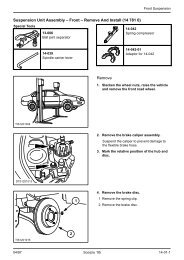
Section Title18. Remove the oil pressure switch.IS<strong>21</strong>0401919. Detach the belt pulley with the crankshaftvibration damper. Lock the flywheel. Remove the bolt.IAS<strong>21</strong>04170<strong>21</strong>–168<strong>21</strong>–14720. Detach the belt pulley with the crankshaftvibration damper (continued). Screw in the bolt fifteen turns. Insert the special tool <strong>and</strong> pull off thevibration damper. Remove the bolt <strong>and</strong> the Woodruff key.IAS<strong>21</strong>0415732<strong>21</strong>. Detach the flywheel.1 Six bolts.2 Pressure plate.3 Flywheel.4 Adaptor plate.22. Detach the oil filter.ELS<strong>21</strong>0416114xx/xx Model 00-01-7
Section Title23. Remove the crankshaft pilot bearing.<strong>21</strong>–036 AS<strong>21</strong>04035CAUTION: Oil sludge <strong>and</strong> abradedparticles must not get into the engine.24. Remove the sump downwards(18 bolts/six nuts).S<strong>21</strong>04025CAUTION: Take care not to damage thecylinder liners.25. Remove the carbon from the upper edgesof the cylinder bores.S<strong>21</strong>04026xx/xx Model 00-01-8
Section TitleS<strong>21</strong>0402726. Remove the hydraulic tappets. Place a suitable drain tray under the cylinderblock. Place the cylinder block in the verticalposition.NOTE: Do not mix up the tappets whenremoving <strong>and</strong> installing them <strong>and</strong> do notdismantle them. They are only available as asingle part for servicing. Press out the hydraulic tappets with a bentpiece of brass wire.27. Detach the oil baffle.S<strong>21</strong>0402828. Detach the oil pump with the intakepipe.Remove the oil pump drive shaft.S<strong>21</strong>04029xx/xx Model 00-01-9
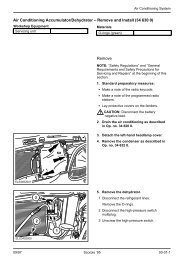
Section Title29. Detach the coolant pump.S<strong>21</strong>0403030. Detach the timing cover.Remove the oil seal from the timing cover.S<strong>21</strong>040313231. Remove the camshaft chain drivecomplete.CAUTION: The oil-filled plunger of thechain tensioner is spring-loaded.1 Chain tensioner (two bolts)2 Camshaft sprocket3 Timing chain4 Crankshaft sprocket5 Chain guide (two bolts)154S<strong>21</strong>04032xx/xx Model 00-01-10
Section Title232. Remove the camshaft.1 Detach the thrust plate (two bolts).2 Carefully withdraw the camshaft with thesprocket bolt. Swivel the engine.1S<strong>21</strong>040335544CAUTION: Do not damage the crankshaftbearing journal.33. Remove the pistons. Detach the big-end bearing caps. Remove the bearing shells from the big-endbearing caps <strong>and</strong> the connecting rods <strong>and</strong>mark them. Press out the pistons with the connectingrods.D<strong>21</strong>05203xx/xx Model 00-01-11
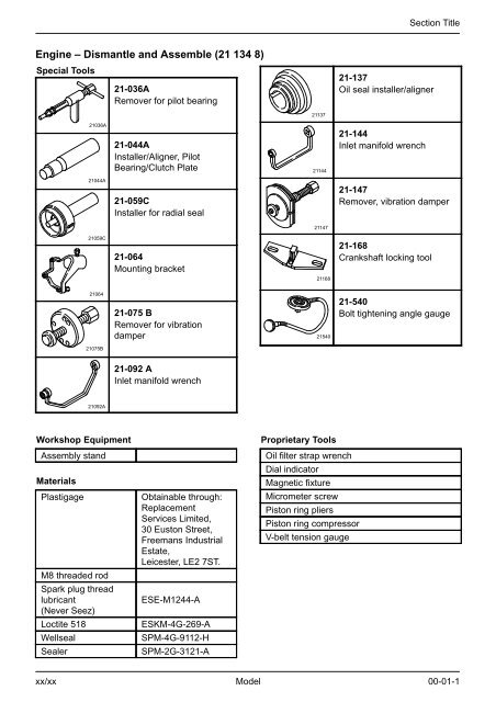
Section Title34. Remove the crankshaft.NOTE: Four special bolts for securing the oilbaffle. Detach the main bearing caps. Lift out the crankshaft. Remove the rear oil seal. Remove the bearing shells <strong>and</strong> mark themfor reuse.S<strong>21</strong>04166<strong>Assemble</strong>35. Preparatory measures.Thoroughly clean all mating <strong>and</strong> bearingsurfaces <strong>and</strong> re-usable parts <strong>and</strong> checkthem for damage.xx/xx Model 00-01-12
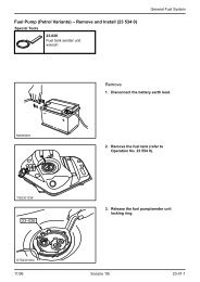
Section TitleMeasure the cylinder boresNOTE: Machine or renew the cylinder block asnecessary.36. Measure the cylinder bores. Measure dimensions A, B, <strong>and</strong> X-Y <strong>and</strong>compare them with the values in theTechnical Data. Ovality = X-Y Conicity = A-B10mmAXYBD<strong>21</strong>0520610mmMeasure the piston diameterNOTE: Piston classification, if a piston has to berenewed.37. Measure the piston diameter. Measure the piston diameter at the top ofthe piston pin bore.D<strong>21</strong>05207xx/xx Model 00-01-13
Section TitleCAUTION: Do not mix up the piston rings.Refit the piston rings in the same positionas before.38. Check the piston ring gaps.The figures indicated in the Technical Dataare for a gauge ring used in production. Thefigures measured in the cylinder can exceedthese by 0,15 mm.D<strong>21</strong>0520839. Measure the diameter of the main <strong>and</strong>big-end bearing journals. Repeat each measurement at 90. Overhaul or renew the crankshaft asnecessary.D<strong>21</strong>05<strong>21</strong>4Measure the bearing clearance40. Paint marks on the main bearing caps. If the parent bore in the cylinder block hasst<strong>and</strong>ard dimensions, it does not have amark. Bearing caps for a 0,38 mm oversize parentbore have a white paint mark.S<strong>21</strong>04556S<strong>21</strong>0454041. Paint marks on the main <strong>and</strong> big-endbearing shells. St<strong>and</strong>ard bearing shells do not have a mark. Bearing shells for an oversize cylinder block<strong>and</strong> an undersize crankshaft are marked onthe back as appropriate (see PartsMicrofiche). If a repair is carried out in production, thebearing shells are provided with paint marksas shown.xx/xx Model 00-01-14
Section TitleS<strong>21</strong>0454142. Paint marks on the main <strong>and</strong> big-endbearing journals. Main bearing journals with the st<strong>and</strong>arddiameter are not marked. In the case of bearing journals with 0,25 mmundersize, the first counterweight on thecrankshaft has a green paint mark. Big-end bearing journals with the st<strong>and</strong>arddiameter are not marked. In the case of big-end bearing journals with0,25 mm undersize, the first crankshaft webin relation to the big-end bearing journal ismarked with a green spot.CAUTION: Do not damage the crankshaftbearings during fitment.43. Fit the crankshaft. Fit the main bearing shells in the cylinderblock. Fit the crankshaft without lubrication.S<strong>21</strong>0453744. Measure the crankshaft main bearingclearance. Measure the clearance of the bearings inturn in numerical order (1 – 4). Thenumbering starts at the timing chain end. Lay a length of Plastigage thread on thebearing journal across the bearing.M<strong>21</strong>01727xx/xx Model 00-01-15
Section Title97 Nm45. Measure the crankshaft main bearingclearance (continued). Fit the bearing cap with the associatedbearing shell <strong>and</strong> tighten it.CAUTION: The crankshaft must not beturned during the measuring operation. Donot hit the bearing caps. Detach the bearing caps.S<strong>21</strong>04538M<strong>21</strong>01728NOTE: If the measured bearing clearance isoutside the specification of 0,008 - 0,062 mm,then the bearing shells should be renewed <strong>and</strong>the measurement procedure repeated fromstep 44.46. Measure the crankshaft main bearingclearance (continued). Compare the Plastigage thread with thePlastigage scale. The reading corresponds to the bearingclearance.97 Nm47. Fit the crankshaft. Coat all main bearing journals, all bearingshells, the threads of all bolts <strong>and</strong> all boltcontact faces with oil. Arrange the bearing shells <strong>and</strong> fit thecrankshaft. Thinly coat the seat of the rear mainbearing cap with sealer (Loctite 518,ESKM-4G-269-A). Fit the main bearing caps with theassociated bearing shells.NOTE: The arrows point to the timing chainend. The numbering starts at the timing chainend. Tighten the bolts.S<strong>21</strong>04671xx/xx Model 00-01-16
Section Title48. Check the crankshaft end float. Set up a dial indicator. Measure the end float by lifting thecrankshaft with the aid of a screwdriver. Correct the end float as necessary byfitting new flanged bearing shells.S<strong>21</strong>04514S<strong>21</strong>0202449. Fit the pistons with the connecting rods.CAUTION: The upper piston rings arecoated with molybdenum. This coatingmust not be damaged.NOTE: The tapered face ring must be fitted sothat the “TOP” mark faces the piston crown. Fit the piston rings on to the pistons usingproprietary piston ring pliers. Lubricate the piston <strong>and</strong> cylinder bore withengine oil. Distribute the ring gaps evenly around thecircumference (see Technical Data).xx/xx Model 00-01-17
Section TitleS<strong>21</strong>0453450. Fit the pistons with the connecting rods(continued). Compress the piston rings with a proprietarypiston ring compressor.NOTE: The front mark on the piston (arrow)must point in the direction of travel. Thenumbering on the connecting rods starts at thetiming chain end. Fit the pistons. The associated big-endbearing journal must be at BDC. Place the appropriate bearing shells in theconnecting rod <strong>and</strong> bearing cap. Fit the bearing caps.91 27,5<strong>21</strong>,823,36AA5AB54,3 0,539,35 1,2554,3 0,530,75 0,2515 19KX 110KX 900ELZ96<strong>21</strong>176xx/xx Model 00-01-18
Section Title51. Identification of the big-end bearingbolts <strong>and</strong> connecting rods used.530 Nm44Only engines with connecting rods <strong>and</strong> big-endbearing journals with the respectiveidentification codes 6AA <strong>and</strong> KX110.52. Measure the big-end bearing clearance. Measure the big-end bearing clearance asdescribed in sub-operations 44. to 46.5 Renew the bearing shell(s) as necessary.NOTE: Check whether the connection rodshave the specified end float.S<strong>21</strong>0452453. Fit the big-end bearing caps. Lubricate the bearing shells, bearingjournals, threads <strong>and</strong> contact faces of theconnecting rod nuts with engine oil.NOTE: The connecting rods <strong>and</strong> their bearingcaps have the same numbers. Fit the big-end bearing caps with the bearingshells <strong>and</strong> tighten them.xx/xx Model 00-01-19
Section Title20 NmELS<strong>21</strong>05870Only engines with connecting rods <strong>and</strong> big-endbearing journals with the respectiveidentification codes 5AB <strong>and</strong> KX900.NOTE: Use the old bolts to measure thebearing clearance.54. Measure the big-end bearing clearance. Measure the big-end bearing clearance asdescribed in sub-operations 44. to 46. Renew the bearing shell(s) as necessary.NOTE: Check whether the connection rodshave the specified end float.NOTE: Use new bolts.55. Fit the big-end bearing caps. Lubricate the bearing shells, bearingjournals, threads <strong>and</strong> contact faces of theconnecting rod nuts with engine oil.NOTE: The connecting rods <strong>and</strong> their bearingcaps have the same numbers. Fit the big-end bearing caps with the bearingshells <strong>and</strong> tighten them.NOTE: The oil seal points outwards.56. Install the crankshaft pilot bearing.S<strong>21</strong>04535<strong>21</strong>–044 Axx/xx Model 00-01-20
Section Title57. Fit the crankshaft rear oil seal. Lubricate the crankshaft running face <strong>and</strong>oil seal lip with oil. Support the special tool in a vice. Insert the oil seal with the open sideupwards <strong>and</strong> drive it in carefully as far as itwill go using the h<strong>and</strong>le of a hammer. Fit the special tool with the oil seal to theengine. Drive in the oil seal evenly as far as it willgo. Swivel the engine.<strong>21</strong>–059 CS<strong>21</strong>0451511 Nm58. Install the camshaft. Lubricate the camshaft bearings, thecamshaft <strong>and</strong> the thrust plate with oil. Screw in the sprocket bolt half way <strong>and</strong> fitthe camshaft.NOTE: The oil bore in the thrust plate must beat the bottom. Fit the thrust plate. Take out the sprocket bolt.S<strong>21</strong>04533xx/xx Model 00-01-<strong>21</strong>
Section Title59. Check the camshaft end float.S<strong>21</strong>04539Install the chain drive.11 Nm60. Attach the chain guide.61. Align the camshaft <strong>and</strong> crankshaft inrelation to one another.The recesses on both crankshaft journalsmust be opposite one another.S<strong>21</strong>0454262. Preload the chain tensioner.Press the spring <strong>and</strong> the oil-filled plungerinto the chain tensioner <strong>and</strong> fit the oil-filledplunger in the sliding block.S<strong>21</strong>0456363. Preload the chain tensioner (continued).Press the oil-filled plunger <strong>and</strong> sliding blockright into the chain tensioner <strong>and</strong> hold it inthis position.S<strong>21</strong>04564xx/xx Model 00-01-22
Section TitleNOTE: A locking clip is supplied with new chaintensioners. If necessary, fabricate a locking clipfrom welding rod.64. Preload the chain tensioner (continued).Immobilise the sliding block in this positionwith a locking clip.S<strong>21</strong>0455<strong>21</strong>0 Nm64 Nm4365. Fit the camshaft chain drive.NOTE: The dots on the sprockets must beexactly opposite each other on the inside.1 Crankshaft sprocket.2 Crankshaft Woodruff key.3 Camshaft sprocket.4 Timing chain.5 Chain tensioner.6 Remove the locking clip after tensioner hasbeen fitted.511 Nm162S<strong>21</strong>04532<strong>21</strong>–13719 Nm66. Fit the timing cover. Fit the timing cover with a gasket <strong>and</strong> screwthe bolts in fingertight. Centre the timing cover using the specialtool <strong>and</strong> align it to the sump mating face. Tighten the nine bolts. Remove the special tool.S<strong>21</strong>04531xx/xx Model 00-01-23
Section Title<strong>21</strong>–13767. Fit the new crankshaft front oil seal. Lubricate the oil seal lip <strong>and</strong> the crankshaftwith oil. Insert the oil seal lip as far as it will go. Remove the bolt <strong>and</strong> the special tool.S<strong>21</strong>045452315 Nm68. Fit the adaptor plate in place <strong>and</strong> attachthe flywheel.CAUTION: Use new bolts. Immobilise the crankshaft in the cylinderblock.1 Place the adaptor plate on the guidesleeves.ELS<strong>21</strong>0466130 Nm85412 Flywheel.3 Pressure plate.4 Bolts.69. Attach the oil filter.Lubricate the oil seal with clean engine oil.45 Nm 8570. Fit the belt pulley with the vibrationdamper. Immobilise the flywheel. Lubricate the belt pulley bore with oil. Fit the belt pulley with the bolt by means ofthe Woodruff key on the crankshaft. Loosen the bolt, apply sealer(SPM-2G-31<strong>21</strong>-A) <strong>and</strong> re-tighten it.IAS<strong>21</strong>04658xx/xx Model 00-01-24
Section Title9 Nm71. Fit the coolant pump. Coat the coolant pump mating faces <strong>and</strong> thetiming cover with sealer (specificationESKM-4G-269-A). Fit the coolant pump with an oil seal.S<strong>21</strong>045301128 mm<strong>21</strong>9 Nm72. Fit the driveshaft <strong>and</strong> the oil pump withthe intake pipe.NOTE: The short pointed end of the shaftpoints towards the distributor.1 Set the retaining ring in its correct positionon the drive shaft <strong>and</strong> fit the shaft. Fill the oil pump with oil through the intakepipe <strong>and</strong> turn it by h<strong>and</strong>.2 Fit the oil pump.1S<strong>21</strong>04529xx/xx Model 00-01-25
Section Title73. Fit the oil baffle.19 NmS<strong>21</strong>045285 Nm 8 Nm25 Nm5 Nm8 NmFit the sump.74. Apply sealer (Loctite 518,ESKM-4G-269-A) as follows: To the gap at the cylinder block/timingcover mating face. To the groove in the rear main bearing cap.75. Fit the sump with a new one-piecegasket. Fit the gasket over the studs on thecylinder block.NOTE: The knobs on the sump must engagein the corresponding holes in the gasket. Fit the sump <strong>and</strong> screw on the nuts. Tighten the nuts <strong>and</strong> bolts in two stages.76. Fit the oil drain plug using a new seal.S<strong>21</strong>0452577. Tighten the sump nuts <strong>and</strong> bolts.1 Start – stage 1.2 Start – stage 2.<strong>21</strong>S<strong>21</strong>04546xx/xx Model 00-01-26
Section TitleNOTE: Fit the hydraulic tappets in the correctsequence.NOTE: Hydraulic tappets that are new orcontain no oil should be pumped up manually inoil before installation until they cannot becompressed any more.78. Fit the hydraulic tappets.S<strong>21</strong>04527Install the cylinder headsS<strong>21</strong>0455379. Fit new cylinder head gaskets. The cylinder block <strong>and</strong> cylinder head matingfaces must be dry <strong>and</strong> clean. The gaskets are marked “TOP FRONT” <strong>and</strong>are guided into place with the locatingsleeves. The left <strong>and</strong> right-h<strong>and</strong> gaskets are different.80. Fit the cylinder heads.The cylinder heads are guided into locatingsleeves.xx/xx Model 00-01-27
Section Title6578173 Nm438 Nm3223148756S<strong>21</strong>04565CAUTION: Use new bolts.81. Pre-tighten the cylinder head bolts. Oil the heads <strong>and</strong> the threads of thecylinder head bolts <strong>and</strong> screw them in. Pre-tighten the cylinder head bolts in twostages <strong>and</strong> in the indicated sequence.<strong>21</strong>–540 90CAUTION: The cylinder head bolts mustnot be retorqued.82. Tighten the cylinder head bolts.Wait five minutes after the second stage <strong>and</strong>then tighten the bolts a further 90.J<strong>21</strong>05623xx/xx Model 00-01-28
Section Title83. Fit the oil pressure switch.S<strong>21</strong>0451927 NmInstall the inlet manifold.S<strong>21</strong>0454784. Fit the gasket. Apply sealer (Wellseal, SPM-4G-9112-H) tothe contact faces of the cylinder block <strong>and</strong>cylinder heads <strong>and</strong> the inlet manifold flange. Fit the gasket. Apply sealer (SPM-4G-9112-H) to the fourprojecting areas of the inlet manifold tocylinder head gasket.3 5 7 223 Nm 18 Nm 12 Nm 6 Nm85. Fit the inlet manifold (seven bolts, onenut).Tighten the inlet manifold in four stages asillustrated.IAS<strong>21</strong>046591684xx/xx Model 00-01-29
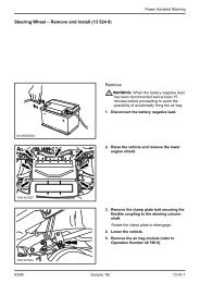
Section Title231419 Nm1S<strong>21</strong>0467286. Fit the distributor. Set cylinder no. 1 to TDC.1 Align the notches on the distributor base<strong>and</strong> the cylinder block.2 The distributor rotor points towards thenotch on the edge of the distributor. Press the distributor down <strong>and</strong> engage thepinion. Crank the engine <strong>and</strong> bring the distributorinto engagement with the oil pump driveassembly.3 Position of the distributor rotor (cylinderno. 1 in TDC position) with the distributorinstalled.4 Secure the distributor with the retainingplate (one bolt).xx/xx Model 00-01-30
Section Title32 Nm9087. Fit the rocker shafts. Lubricate the push rods with oil <strong>and</strong> fit them.CAUTION: Do not under anycircumstances adjust the rocker arms. Fit the rocker shafts in their correct positions<strong>and</strong> screw in the bolts. Tighten the bolts.S<strong>21</strong>0451388. Fit the fuel rail (four bolts).12 NmIAS<strong>21</strong>04652NOTE: Use new rubber seals at the injectors.89. Fit the injectors.IAS<strong>21</strong>04153Attach the cylinder head coversNOTE: Stick the gaskets in place with theadhesive-coated side facing the cylinder headcover.90. Coat the contact faces of the cylinderhead cover flange with sealer(SPM-2G-31<strong>21</strong>-A).Arrange the gaskets in position.S<strong>21</strong>04549xx/xx Model 00-01-31
Section Title7 Nm91. Fit the cylinder head covers (eight bolts<strong>and</strong> washers each).IAS<strong>21</strong>046549 Nm92. Fit the inlet air plenum chamber <strong>and</strong>throttle housing.Insert the positive crankcase ventilation(PCV) hose into the left-h<strong>and</strong> cylinder headcover.IAS<strong>21</strong>0466025 Nm93. Attach the belt pulley to the coolantpump.S<strong>21</strong>0450894. Fit the alternator bracket.IAS<strong>21</strong>0465625 Nmxx/xx Model 00-01-32
Section Title95. Fit the alternator.IAS<strong>21</strong>0465525 NmNOTE: Apply lubricant (Never Seez,ESE-M1244-A) to the spark plug threads.96. Fit the spark plugs.Torque: 32 Nm97. Fit the distributor cap <strong>and</strong> HT leads.IAS<strong>21</strong>04151298. Fit the distributor arc shield.1 Push the arc shield on <strong>and</strong> ensure that itengages correctly.2 Join the spark plug connectors.1IAS<strong>21</strong>0465028 NmNOTE: Use new gaskets.99. Top up the engine oil <strong>and</strong> insert thedipstick.100.Remove the engine from the assemblyst<strong>and</strong>.101.Fit the right-h<strong>and</strong> exhaust manifold.ELS<strong>21</strong>04663xx/xx Model 00-01-33
Section Title9 Nm102.Fit the heat shield to the right-h<strong>and</strong>exhaust manifold.103.Fit the bracket with the engine mountingbracket on the cylinder block (four bolts).50 NmELS<strong>21</strong>0466423 Nm<strong>21</strong>–144NOTE: Bolt-tightening sequence.104.Retorque the inlet manifold bolts. Install the engine <strong>and</strong> let it run to operatingtemperature. Retorque the bolts. Retorque the nuts using SpecialTool <strong>21</strong>-092 A.3 5 7 223 NmPZS<strong>21</strong>046681684xx/xx Model 00-01-34