Mini-Space Series Installation, Operation & Maintenance Manual
Mini-Space Series Installation, Operation & Maintenance Manual
Mini-Space Series Installation, Operation & Maintenance Manual

Create successful ePaper yourself
Turn your PDF publications into a flip-book with our unique Google optimized e-Paper software.
<strong>Mini</strong>-<strong>Space</strong> <strong>Series</strong> <strong>Installation</strong>, <strong>Operation</strong> & <strong>Maintenance</strong> <strong>Manual</strong>(©April, 2008)Air Technology Systems, Inc.
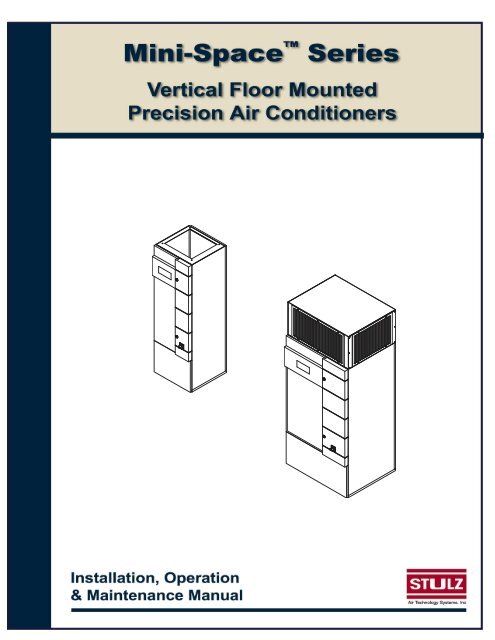
<strong>Mini</strong>-<strong>Space</strong> <strong>Series</strong> <strong>Installation</strong>, <strong>Operation</strong> & <strong>Maintenance</strong> <strong>Manual</strong><strong>Mini</strong>-<strong>Space</strong> - Vertical Floor SystemsMODEL NOMENCLATURECC U-12 1-GCC= Compact Line SystemUD= Upflow Air Pattern= Downfl ow Air PatternACWGW= Air Cooled= Chilled Water System= Glycol Cooled= Water Cooled46812 = Nominal Capacity in kW1720Number of Refrigeration CircuitsAIR INLETAIR OUTLETAIR INLETAIR OUTLETCCU= UpflowAir PatternsCCD= DownflowAir Patterns(©April, 2008)Air Technology Systems, Inc.
<strong>Mini</strong>-<strong>Space</strong> <strong>Series</strong> <strong>Installation</strong>, <strong>Operation</strong> & <strong>Maintenance</strong> <strong>Manual</strong>1.0 INTRODUCTION1.1 GeneralCongratulations, the <strong>Mini</strong>-<strong>Space</strong> floor mountedprecision air conditioning system covered by thismanual is designed and manufactured by Stulz AirTechnology Systems, Inc. (SATS) using the lateststate-of-the-art control technology. Recognized as aworld leader, SATS provides air conditioning systemswith the highest quality craftsmanship using the fi n-est materials available in the industry. The unit willprovide years of trouble free service if installed andmaintained in accordance with this manual. Damageto the unit from improper installation, operation ormaintenance is not covered by the warranty.STUDY the instructions contained in this manual.They must be followed to avoid difficulties. Spareparts are available from SATS to insure continuousoperation. Using substitute parts or bypassing electricalor refrigeration components in order to continueoperation is not recommended and will VOID THEWARRANTY. Due to technological advancements,components are subject to change without notice.<strong>Mini</strong>-<strong>Space</strong> systems and centrifugal condensers aredesigned to be installed indoors, unless otherwisenoted on the equipment. Propeller-type condensers,drycoolers and pump packages are designed foroutdoor use.1.2 Product Description<strong>Mini</strong>-<strong>Space</strong> precision A/C systems are designed to bethe most compact and flexible, floor mounted air conditioningsystems in the industry. The unit is availablein air-cooled, water-cooled and glycol-cooled configurations.The cooling capacity in BTU/Hr will dependon the unit size, which can range from 12,000 to84,000 BTU/Hr. <strong>Mini</strong>-<strong>Space</strong> systems are designed tooperate with either R22 or R407C refrigerant. Referto the unit nameplate to identify which refrigerant isused with your system.NOTE<strong>Mini</strong>-<strong>Space</strong> systems are designed to supply airto only one room.<strong>Mini</strong>-<strong>Space</strong> precision A/C units are compact and versatile.The functional modes of operation in additionto cooling are heating, humidification and dehumidifi -cation, which provide complete environmental controlof a conditioned space. The cabinet is available intwo footprint sizes. A compact 23.6 inches wide by23.6 inches deep frame for units ranging from 18,000to 48,000 BTU/Hr and a compact 39.4 inches wide by31.9 inches deep frame for units ranging from 48,000to 76,000 BTU/Hr. The cabinet is designed for convenient,100% front access and may easily be tuckedbetween cabinetry or placed side-by-side.There are two airfl ow pattern confi gurations; upflowand downfl ow. The basic cabinet height remains thesame, (72.8”), regardless of the confi guration. An optionalplenum box may be selected (for upfl ow unitsonly), which adds an extra 18.5” to the height. Seethe installation drawing provided with your unit for thelayout and dimensions of the cabinet.The <strong>Mini</strong>-<strong>Space</strong> unit is provided with a factory mountedmain power disconnect switch with a lockablehandle. The disconnect switch electrically isolates theunit during routine maintenance. The system incorporatesstate-of-the-art component protection with theuse of motor start protectors and circuit breakers.The standard controller for the <strong>Mini</strong>-<strong>Space</strong> unit isthe C1002 microprocessor, which provides the followingfeatures: input/output monitoring status, fullintegrated control of heating, cooling, humidifi cationand dehumidifi cation; multi-unit control and remotecommunication with building management systems.The controller is typically factory mounted on thefront hinged access door of the unit. As an optionthe controller may be remotely mounted to a wall orcontrol panel.SATS offers the C5000 microprocessor controller asan option if required for selected special applications.C1002C5000An operating manual for the system controller is providedunder separate cover. Refer to that manual fordetailed instructions on operating the system controllerprovided with your unit.(©April, 2008)1-1Air Technology Systems, Inc.
<strong>Mini</strong>-<strong>Space</strong> <strong>Series</strong> <strong>Installation</strong>, <strong>Operation</strong> & <strong>Maintenance</strong> <strong>Manual</strong>1.3 Product WarrantySATS offers a two year standard limited warranty as stated on the following pages. Additionally an extendedwarranty may be purchased on the unit’s compressor. Consult the factory to verify if the extended compressorwarranty was purchased for your system. The extended compressor warranty as stated on the next page will besent with your unit and should be retained for future reference.2-Year Standard Limited Warranty:Stulz Air Technology Systems, Inc., warrants to the original buyer of its products that thegoods are free from defects in material and workmanship. Stulz Air Technology Systems,Inc.’s obligation under this warranty is to repair or replace, at its option, free of charge to thecustomer, any part or parts which are determined by Stulz Air Technology Systems Inc. to bedefective for a period of 24 months from date of shipment when a completed start-up formhas been submitted to Stulz Air Technology Systems, Inc. within 90 days from shipment. Inthe event that a completed start-up form is not received by Stulz Air Technology Systems, Inc.within 90 days from shipment, the company’s obligation will be for a period of 12 months fromdate of shipment. Parts repaired or replaced under this warranty are shipped FOB Factory,and warranted for the balance of the original warranty period or for 90 days from the date ofinstallation, whichever is greater.Stulz Air Technology Systems, Inc.’s warranty does not cover failures caused by improperinstallation, abuse, misuse, misapplication, improper or lack of maintenance, negligence,accident, normal deterioration (including wear and tear), or the use of improper parts orimproper repair.Purchaser’s remedies are limited to replacement or repair of nonconforming materials in accordancewith the written warranty. This warranty does not include costs for transportation,costs for removal or reinstallation of equipment or labor for repairs or replacement made inthe field.If any sample was shown to the buyer, such sample was used merely to illustrate the generaltype and quality of the product, and not to represent that the equipment would necessarilyconform to the sample.This is the only warranty given by the seller, and such warranty is only given to buyers forcommercial or industrial purposes. This warranty is not enforceable until the invoice(s) ispaid in full.THE FOREGOING SHALL CONSTITUTE SATS’S ENTIRE LIABILITY AND YOUR EXCLU-SIVE REMEDY. IN NO EVENT SHALL SATS BE LIABLE FOR ANY DIRECT, INDIRECT,SPECIAL, INCIDENTAL, CONSEQUENTIAL, OR EXEMPLARY DAMAGES, INCLUDINGLOST PROFITS (EVEN IF ADVISED OF THE POSSIBILITY THEREOF) ARISING IN ANYWAY OUT OF THE INSTALLATION, USE OR MAINTENANCE OF THE EQUIPMENT. THISWARRANTY IS IN LIEU OF ALL OTHER WARRANTIES, EXPRESS OR IMPLIED, INCLUDINGWARRANTIES OF MERCHANTABILITY OR FITNESS FOR A PARTICULAR PURPOSE.1-2(©April, 2008)Air Technology Systems, Inc.
<strong>Mini</strong>-<strong>Space</strong> <strong>Series</strong> <strong>Installation</strong>, <strong>Operation</strong> & <strong>Maintenance</strong> <strong>Manual</strong>Optional Limited Extended Warranty (5 Years Total)Stulz Air Technology Systems, Inc., warrants to the original buyer of its product thatthe compressor(s) listed below are warranted for parts replacement (not includinglabor) for an extended period of 4 years from the date of expiration of the standardequipment warranty.Stulz Air Technology Systems’ warranty does not cover failures caused by improper installation,abuse, misuse, misapplication, improper or lack of maintenance, negligence,accident, normal deterioration including normal wear and tear, or the use of improperparts or improper repair as determined by SATS.This warranty does not include costs of transportation, cost for removal or reinstallationof equipment or labor for repairs or replacement made in the fi eld.The obligation and liability of Stulz Air Technology Systems under this warranty doesnot include losses, direct or indirect, for incidental or consequential damages.Compressor Serial No.: __________________________________Unit Model No.: __________________________________Unit Serial No.: __________________________________Stulz Air Technology Systems Job No.: __________________________________End User: __________________________________Date: __________________________________(©April, 2008)1-3Air Technology Systems, Inc.
<strong>Mini</strong>-<strong>Space</strong> <strong>Series</strong> <strong>Installation</strong>, <strong>Operation</strong> & <strong>Maintenance</strong> <strong>Manual</strong>1.4 Safety1.4.1 GeneralStulz Air Technology Systems, Inc. uses NOTESalong with CAUTION and WARNING symbolsthroughout this manual to draw your attention to importantoperational and safety information.A bold text NOTE marks a short message in the informationto alert you to an important detail.A bold text CAUTION safety alert appears with informationthat is important for protecting your equipmentand performance. Be especially careful to read andfollow all cautions that apply to your application.A bold text WARNING safety alert appears with informationthat is important for protecting you from harmand the equipment from damage. Pay very close attentionto all warnings that apply to your application.A safety alert symbol precedes a generalWA RNING or CAUTION safety statement.A safety alert symbol precedes an electricalshock hazard WARNING or CAUTION safety statement.1.4.2 Safety SummaryThe following statements are general guidelines followedby warnings and cautions applicable throughoutthe manual.Prior to performing any installation, operation,m a intenance or troubleshooting procedure read andunderstand all instructions, recommendations andguidelines contained within this manual.Never operate the unit with any cover, guard,screen panel, etc. removed unless the instructionss p ecifically state otherwise, then do so with extremecaution to avoid personal injury.Never lift any component in excess of 35 poundswithout help. If a lifting device is used to move a unit,ensure it is capable of supporting the unit.Always disconnect the main power supply to theequipment at the main power disconnect switchbefore beginning work on the equipment. A lock-outtag-out procedure should be followed to ensure thatpower is not inadvertently reconnected.Never work on electrical equipment unless anotherperson, who is familiar with the operation and hazardsof the equipment and competent in administeringfi rst aid, is nearby.All personnel working on or near equipment shouldbe familiar with hazards associated with electricalmaintenance. Safety placards/stickers have beenplaced on the unit to call attention to all personal andequipment damage hazard areas.Certain maintenance or cleaning procedures maycall for the use and handling of chemicals, solvents,or cleansers. Always refer to the manufacturer’sMaterial Safety Data Sheet (MSDS) prior to usingthese materials. Clean parts in a well-ventilated area.Avoid inhalation of solvent fumes and prolongedexposure of skin to cleaning solvents. Wash exposedskin thoroughly after contact with solvents.WARNINGThis equipment should be serviced and repairedby journeyman, refrigeration mechanicor an air conditioning technician.WARNINGThis unit employs high voltage equipment withrotating components. Exercise extreme care toavoid accidents and ensure proper operation.WARNINGHazardous voltage will still be present insidethe electric box at the motor start protectorsand circuit breakers, even with the unit turnedoff at the microprocessor controller. To isolatethe unit for maintenance, turn off power at themain power disconnect switch. Always disconnectmain power prior to performing any serviceor repairs.When working on electrical equipment, remove alljewelry, watches, rings, etc.1-4(©April, 2008)Air Technology Systems, Inc.
<strong>Mini</strong>-<strong>Space</strong> <strong>Series</strong> <strong>Installation</strong>, <strong>Operation</strong> & <strong>Maintenance</strong> <strong>Manual</strong>WARNINGRefrigerant (R22 or R407C) is used with thisequipment. Death or serious injury may result ifpersonnel fail to observe proper safety precautions.Great care must be exercised to preventcontact of liquid refrigerant or refrigerant gas,discharged under pressure, with any part of thebody. The extremely low temperature resultingfrom the rapid expansion of liquid refrigerantor pressurized gas can cause sudden and irreversibletissue damage.As a minimum, all personnel should wear thermalprotective gloves and face-shield/goggleswhen working with refrigerant. Application ofexcessive heat to any component will causeextreme pressure and may result in a rupture.CAUTIONDo not use cleaning solvents near open fl ameor excessive heat. Wear eye protection whenblowing solvent from parts. The pressure-washshould not exceed 30 psig. Solvent solutionsshould be disposed of in accordance with localand state regulatory statutes.CAUTIONThe unit must be kept in its normal installedp o sition when moving. If the unit is not keptlevel and vertical, damage to the compressorwill result.Exposure of refrigerant to an open fl ame or avery hot surface will cause a chemical reactionthat will form carbonyl chloride (hydrochloric/hydrofluoricacid), a highly poisonous and corrosivegas commonly referred to as PHOSGENE.In its natural state, refrigerant is a colorless,odorless vapor with no toxic characteristics. Itis heavier than air and will disperse rapidly ina well-ventilated area. In an unventilated area,it presents a danger as a suffocant.WARNINGWhen performing soldering or de-solderingoperations, make certain the refrigerations y stem is fully recovered and purged and drynitrogen is flowing through the system at the rateof not less than 1-2 CFM (0.03-0.06M³/minute).CAUTIONWhen the air conditioner is in the cooling mode,the return air-intake and discharge (supply) mustbe free of obstructions. Ensure access panels/doors are secure and latched into position.(©April, 2008)1-5Air Technology Systems, Inc.
<strong>Mini</strong>-<strong>Space</strong> <strong>Series</strong> <strong>Installation</strong>, <strong>Operation</strong> & <strong>Maintenance</strong> <strong>Manual</strong>1.5 General DesignThe <strong>Mini</strong>-<strong>Space</strong> unit is housed in a steel frame type cabinet and is rated for indoor use. The exterior of the cabinetis coated with a powder coat finish to protect against corrosion. Hinged doors are located in the front of thecabinet for easy access to components. Operator controls are conveniently located on the front of the cabinet.Figure 1 depicts a typical internal layout of a CCU-121-A (upfl ow) unit and identifi es the major components.Location of the major components vary depending on <strong>Mini</strong>-<strong>Space</strong> model number and options purchased.CONTROLLERSIDE PANEL (CUT-AWAYTO SHOW INTERIOR)DOOR LOCK (2 PLACES)BLOWERELECTRIC BOXHEATERS (ELECTRIC)T/H SENSORFIRESTATCOILCONDENSATE PANSMOKE DETECTORRECEIVERPOP-OFF FILTER/ACCESS PANEL(CUT-AWAY TO SHOW INTERIOR)SERVICE DISCONNECT SWITCHHUMIDIFIERCOMPRESSORLEFT SIDEFRONTFigure 1- Typical Upflow Internal Layout(Model CCU-041-A shown for reference)Figure 2 depicts a typical internal layout of a CCD-171-W/G (downflow) unit and identifi es the major components.Location of the major components vary depending on <strong>Mini</strong>-<strong>Space</strong> model number and options purchased.ELECTRIC BOXFILTER(CCD-171-201 UNITS)T/H SENSORDOOR LOCK(2 PLACES)CONTROLLERHEATERFIRESTATSMOKEDETECTORFILTER(CCD-041/121 UNITS)COILBLOWER MOTORSERVICE DISCONNECTSWITCHCONDENSATE PANBLOWERRECEIVERHUMIDIFIERCOMPRESSORSIDE PANEL (CUT-AWAYTO SHOW INTERIOR)FRONTRIGHT SIDEFigure 2- Typical Downflow Internal Layout(Model CCD-171-W/G shown for reference)1-6(©April, 2008)Air Technology Systems, Inc.
<strong>Mini</strong>-<strong>Space</strong> <strong>Series</strong> <strong>Installation</strong>, <strong>Operation</strong> & <strong>Maintenance</strong> <strong>Manual</strong>1.5.1 Electric Box AccessThe electrical components are protected behind thefront, hinged access door located on the right side ofthe unit. The electric box door is locked in 2 places.To open the access door, turn the door locks with thetriangular key wrench provided. The electric box dooris also safety interlocked with the main power servicedisconnect switch preventing the door from openingwhen the switch is in the “On” position. The switchmust be turned “Off” to gain access to the electricalcompartment.The service disconnect switch may be used to turnthe unit off for emergency shutdown or when routinemaintenance is performed. The handle of the switchmay be locked in the “Off” position to prevent unintendedoperation.1.5.2 Circuit Breakers / Motor Start ProtectorsIndividual overload protection is provided by circuitbreaker(s) and motor start protectors. These switchesmust be manually reset once the overload conditionis cleared.1.5.3 Heaters (Optional)Heaters may be furnished for reheating the supplyair, as required to offset the sensible cooling of thesystem during the dehumidification cycle, and forthe automatic heating mode. As a standard, electricresistance heating elements are factory installed inthe supply airstream to heat the supply air.As an option, hot water reheat may be selected. A hotwater heating coil is factory installed in the supply airstream to heat the supply air. A valve is provided tocontrol the flow of hot water through the coil to maintainthe correct reheat temperature.1.5.4 Coil(s)The cooling and optional hot water reheating coils arealuminum fi nned/copper tube construction. The coilsare leak tested and cleaned before installation by thefactory.1.5.5 BlowerThe unit is equipped with a centrifugal blower withforward curved blades. The blower is dynamically andstatically balanced to minimize vibration. The bloweris contained in a double-width, double-inlet housing.The blower motor is ODP industrial duty. Smallerunits, models CCU/D-41/121, use a direct drive blowerwhich may be adjusted via a fan speed controllerlocated in the electric box.(©April, 2008)Larger units, models CCU/D-171/201 use a belt driveblower. The motor is mounted on an adjustable basefor belt tensioning and is furnished with an adjustablepitch sheave to adjust the blower speed.1.5.6 Temperature/Humidity SensorAs a standard for room air control, a temperature/humidity(T/H) sensor is factory mounted in the returnair stream. The (T/H) sensor monitors the return airconditions and provides input signal(s) to the systemcontroller to manage the operation of the A/C unitconsistent with the setpoints entered in the systemcontroller. As an option, sensor(s) may be shippedloose for fi eld installation. Refer to the electricaldrawing supplied with your unit for details specifi c toyour system.1.6 Optional Equipment1.6.1 Humidifier (Optional)<strong>Mini</strong>-<strong>Space</strong> systems may utilize an optional electrode,steam humidifi er. The humidifi er is factoryinstalled inside the air conditioner and includes fi lland drain valves and associated piping. <strong>Operation</strong>of the humidifi er’s fill and drain cycles is based onwater conductivity and is maintained by the humidifiercontroller. An operating manual for the humidifier isprovided under separate cover. Refer to that manualfor detailed information on operation of the humidifi er.1.6.2 Condensate PumpAn optional condensate pump may be used for automaticremoval of condensate from the air conditionerand fl ush water from the humidifi er. An internal overflo w safety switch is wired to the system controllerto automatically shut down the precision A/C systemshould an overfl ow occur.1.6.3 Smoke DetectorOptionally mounted in the return air stream, a photoelectricsmoke detector is used to sense the presenceof smoke and signal the controller when asmoke alarm condition exists.1.6.4 FirestatOptionally mounted in the return air stream, a fi re detectorsenses high return air temperature and signalsthe controller when a fi re alarm condition exists.1-7Air Technology Systems, Inc.
<strong>Mini</strong>-<strong>Space</strong> <strong>Series</strong> <strong>Installation</strong>, <strong>Operation</strong> & <strong>Maintenance</strong> <strong>Manual</strong>2.0 INSTALLATION2-12.1 Receiving the EquipmentYour <strong>Mini</strong>-<strong>Space</strong> precision A/C system has beentested and inspected prior to shipment. To ensurethat your equipment has been received in excellentcondition, make a visual inspection of the equipmentimmediately upon delivery. Carefully remove the shippingcontainer and all protective packaging. Openthe access panels/doors and thoroughly inspect theunit interior for any signs of transit-incurred damage.If there is shipping damage, it must be noted on thefreight carrier’s delivery forms BEFORE signing forthe equipment. Any freight claims MUST be donethrough the freight carrier. SATS ships all equipmentFOB. SATS can assist in the claim filing processwith the freight carrier. Should any damage be present,notify the SATS Product Support Group prior toattempting any repairs. Refer to section five of thismanual for instructions.A unit Data Package has been sent with your unit. Itcontains this manual, a supplemental microprocessorcontroller manual, system drawings, applicableMSDS’s, other component manuals, warranty registrationand other applicable instructions based on theconfiguration and options of your unit. The data packagehas been placed in your unit in a clear plasticenvelope. These documents need to be retained withthe unit for future reference.NOTEItems that have been shipped loose, such ascontrollers, temperature sensors, water detectors,buck/boost transformers etc., are shippedinside the air conditioner unless specifi ed otherwiseby the customer. The duct connectionplate or plenum box (if applicable) are placed ontop of the air conditioner inside the unit’s carton.Remove and store these items in a safe placeunless you are using them immediately.2.2 Site Preparation<strong>Mini</strong>-<strong>Space</strong> systems are designed with easy serviceaccess in mind. Component access panels are locatedon the front of the equipment. In order to havefull service access through the front hinged accessdoor, no permanent obstructions can be placed within28 inches in front of the unit. (See Figure 3)NOTEWorking clearance requirements need to beestablished prior to the mounting of the unit.Refer to local and national electrical codes.CONTROLLERPOP-OFFACCESS PANELS2.0"28.0"Figure 3- <strong>Installation</strong> ClearanceTo minimize the effects of the environment surroundingthe conditioned space, certain steps must betaken. This is especially true for critical/precisionroom preparation (computer rooms/labs) requiringclose tolerance control of temperature and humidity.The conditioned space should be well insulated andinclude a vapor barrier. The installer should ensurethat the proper insulation rating is used based on thedesign of the space, which was the basis for the systemselected. The following chart is a recommendedminimum R-value (thermal resistance) to ensureoptimum equipment operation.STRUCTURE R-VALUECeiling R-38Wall R-21Floor R-19Door R-5HIINGED ELECTRIC BOXACCESS DOORThe vapor barrier is the single most importantrequirement for maintaining environmental controlin the conditioned space. The vapor barrier inthe ceiling and walls can be a polyethylene fi lm.Concrete walls and fl oors should be painted with a2.0"(©April, 2008)Air Technology Systems, Inc.
<strong>Mini</strong>-<strong>Space</strong> <strong>Series</strong> <strong>Installation</strong>, <strong>Operation</strong> & <strong>Maintenance</strong> <strong>Manual</strong>rubber or plastic based paint. Doors and windowsshould be properly sealed and a door sweep usedto minimize leakage. Outside or fresh air should bekept to a minimum (as it adds to the cooling, heating,dehumidification and humidifying loads), whilemaintaining the requirement of the Indoor Air Quality(IAQ) standard. Lack of these steps can cause erraticoperation, unstable room control and excessivemaintenance costs.2.3 Rigging<strong>Mini</strong>-<strong>Space</strong> systems are designed to be kept in avertical position. Move the unit with a suitable devicesuch as a forklift, pallet jack or roller bar and dollies.A weight table is provided on the installation drawingprovided with your unit for reference. The <strong>Mini</strong>-<strong>Space</strong>unit is shipped on a skid to facilitate moving prior toinstallation. The unit should always be stored indoorsin a dry location prior to installation.CAUTIONWhen moving the unit, it must be kept level andin the vertical position to prevent damage.2.4 Mounting/Placement<strong>Mini</strong>-<strong>Space</strong> systems that are not ducted, are designedto be located in the conditioned space.Ducted units may be located either inside or outsidethe conditioned space but are designed to supply airto only one room. <strong>Mini</strong>-<strong>Space</strong> units have a compactfootprint which allows the units to be placed in a corneror between cabinetry. It is recommended that theunit be positioned to obtain optimum air circulation.NOTEPlacement of the fl oor or ceiling registers isimportant. If they are too close to the unit, thesupply air will be recirculated back to the unitbefore it has circulated throughout the space.See Figure 4. The unit is designed to be located ontop of the fl oor (typically upfl ow) or on a raised floor(typically downfl ow).CAUTIONEnsure the mounting surface is able to supportthe weight of the equi[pment. On some raisedfloor installations a floor stand is required,depending on the load capacity of the existingraised fl oor. Before mounting the unit, refer tothe weight table on the installation drawing.UPFLOWDOWNFLOWOPTIONAL 2 OR 3 WAY PLENUM BOX(FIELD INSTALLED)OPTIONAL DUCTCONNECTION PLATEOPTIONAL DUCT CONNECTION PLATE(NOT REQUIRED WITH PLENUM BOX)OPTIONAL FLOOR STANDOPTIONAL TURNING VANEFigure 4- Typical <strong>Installation</strong>(©April, 2008)2-2Air Technology Systems, Inc.
<strong>Mini</strong>-<strong>Space</strong> <strong>Series</strong> <strong>Installation</strong>, <strong>Operation</strong> & <strong>Maintenance</strong> <strong>Manual</strong>2.4.1 Precision A/C UnitSee Figure 6. The <strong>Mini</strong>-<strong>Space</strong> precision A/C systemuses a frame and panel construction for unit rigidityand full service accessibility while the unit is mountedin place. Ensure the mounting surface is capableof supporting the weight of the equipment. Beforemounting the unit, refer to the installation drawing forthe weight of your unit.If a floor stand is selected refer to the installationdrawing provided and cut out the raised floor tomatch the unit’s overall base dimension. If a fl oorstand is not selected, use the installation drawing andcut out the raised fl oor to match the blower dischargeopening and cut out the holes required for piping andwiring through the raised floor.NOTEEquipment must be level to operate properly.An optional duct connection plate may be shippedloose for field installation. To install the duct connectionplate, place it on top of the A/C unit and attach itwith the supplied self-tapping screws. Holes are predrilledin the unit and the connection plate.2.4.2 Outdoor EquipmentBefore installing outdoor equipment, refer to theinstallation manual provided with the equipment.Install the equipment (remote condenser, fluid cooler,pump package) in a secure location where it cannotbe tampered with and the service disconnect switchcannot be inadvertently turned off. Provide a solidbase capable of supporting the weight of the equipment.Mount the equipment to the base to preventit from moving during operation. It is recommendedthat outdoor equipment be mounted with vibrationisolators to reduce the vibration transmitted to themounting surface.Locate remote condenser/condensing units wherethe blower(s) are not likely to draw dirt and debrisinto the coil fins. There should be at least 24 inchesof clearance around the condenser to ensure adequateairflow to the coil.Install a pump package (if applicable) in accordancewith the installation manual and piping diagram providedwith the unit. The pump should be at least 3 feetbelow the height of the expansion tank. Do not formpiping loops adjacent to the pump. Avoid piping veryrigid lines.2.5 Optional Equipment (Field Installed)NOTEDo not mount any optional equipment on unitaccess doors.2.5.1 Floor StandInstall the optional floor stand directly on the sub-floor,ensuring the side with the “FRONT” label is facing thesame direction as the front of the precision A/C unit (seeFigure 5). Refer to the floor stand assembly drawingfor the dimensions required to cut the raised floor. Thefloor stand is designed with adjustable feet on all thelegs, allowing for leveling and overall height adjustment.Refer to the floor stand assembly drawing forminimum and maximum height adjustability of yourfloor stand. To adjust the height, first loosen the middlenuts on each leg. Next, turn the top hex nuts to raise orlower the floor stand. Once the floor stand is level andeven with the raised floor, lock all feet in place by tighteningthe middle hex nuts against the top hex nuts."FRONT" LABELFLOOR STAND LEGTHREADED RODTOP HEX NUTMIDDLE HEX NUTISOLATION PADFigure 5- Optional Floor Stand <strong>Installation</strong>2.5.2 Plenum Box AssemblyTURNING VANE(OPTIONAL)If an optional 2 or 3-way air distribution plenum boxis selected it is typically shipped loose. To install aplenum box, fi rst apply a strip of sealing foam aroundthe top fl ange of the A/C unit or run a bead of siliconesealant. Place the plenum assembly on top of the unit(see Figure 4). Attach the plenum with self-tappingscrews (customer supplied). Holes are predrilled in theunit and the plenum box. Remove the front grille foraccess to the mounting holes.2-3(©April, 2008)Air Technology Systems, Inc.
<strong>Mini</strong>-<strong>Space</strong> <strong>Series</strong> <strong>Installation</strong>, <strong>Operation</strong> & <strong>Maintenance</strong> <strong>Manual</strong>2.5.3 Remote DisplayThe C1002 or C5000 Microprocessor controller issupplied with the <strong>Mini</strong>-<strong>Space</strong> system. As an option, afactory supplied control panel may be remote mounted.For mounting and wiring instructions, refer to thesystem drawings and supplemental controller manualsent in the data package with your unit.2.5.4 Condensate PumpAn optional factory installed condensate pump maybe provided for automatically eliminating condensateand humidifier flush water from the drain pan. Thecondensate pump is typically installed by the factoryinside the A/C unit. If an optional fi eld installedcondensate pump is selected, it should be locatedas near as possible to the air conditioning system.The pump should be positioned so the inlet hole inthe pump is below the drain pan inside the A/C unit.Secure the pump in place with a mounting clamp oruse an adhesive that’s appropriate for the mountingsurface. Ensure the pump is level for proper operation.2.5.5 Remote Temperature/Humidity SensorThe remote (T/H) sensor must be located so that itwill properly sense the temperature/humidity conditionsto be controlled. Depending on the type ofcontrol desired (see Section 2.5.5.1), the sensor(s)may be factory mounted and/or shipped loose forfi eld installation.The T/H sensor should not be mounted near a doorway,near or above any heat producing equipmentor in an area where it would be exposed to directsunlight. Follow the steps below to mount the sensor.(©April, 2008)COVER SCREW1. Using a flat head screwdriver, remove the coverplate from the base of the sensor.2. Place the base temporarily over the wire holeopening in the wall. Level the base and mark themounting hole locations through the two mountingslots.3. Drill the mounting holes and insert the wall anchorsprovided.4. Run the wires coming out of the wall through thebase, then secure the base with the screws provided.5. Make the wiring connections. See Section 2.8,Utility Connections and refer to the wiring diagramsupplied with your unit for details.6. Replace unit cover plate on the base.CAUTIONTake care not to damage the exposed temperature/humiditysensors on the PC board while thecover is removed. The sensors can be damagedif handled improperly.2.5.5.1 Types of controlRoom Air Control (standard)- The A/C unit is providedwith a temperature and humidity (T/H) sensor, factorymounted in the return air stream of the A/C unit. Thereturn air temperature and humidity are monitored bythe system controller and compared to limit values setat the factory. Control outputs are based on setpointsentered into the system controller by the user.As an alternative to locating the T/H sensor inside theA/C unit, it may be fi eld installed on a wall in the conditionedspace for sensing actual room conditions.Supply Air Control- (Optional only with C5000 systemcontrollers.) A field installed T/H sensor may be usedfor supply air control. The sensor is fi eld installed inthe supply air stream. The supply air temperature andhumidity are monitored by the system controller andcompared to limit values set at the factory. Control outputsare based on setpoints entered into the systemcontroller by the user.Room Air Control with Supply Air Limitation- ( O ptionalonly with C5000 system controllers.) The controllermonitors the T/H sensor located in the return airstream and the T/H sensor located in the supply airstream. Control is similar to “Room Air Control” except,the temperature setpoint is automatically increased bythe controller when the measured supply air temperatureexceeds the Start Temperature entered by theuser. The extent of the setpoint increase is determinedby a factor which the user enters in the controller asa gradient. A high gradient signifi cantly corrects thefailure to meet the supply air tempertaure but has therisk that the control circuit starts to hunt.With humidity control, the setpoint shift acts in theopposite direction. If the starting humidity entered by2-4Air Technology Systems, Inc.
<strong>Mini</strong>-<strong>Space</strong> <strong>Series</strong> <strong>Installation</strong>, <strong>Operation</strong> & <strong>Maintenance</strong> <strong>Manual</strong>2-5the user is exceeded by the measured supply airhumidity, the setpoint is autimatically reduced by thecontroller. The user may also enter a gradient factorfor humidity control.Formula:New setpoint = old setpoint+ [gradient • (start value -actualvalue)]Example (temperature): 70.5 = 70 + [0.5 • (61 - 60)]Example (humidity): 49 = 50 + [0.5 • (70 - 72)]Supply Air Control with Room Air Limitation- (Optionalonly with C5000 system controllers.) Based on thesame principle as “Room Air Control with Supply AirLimitation” however, in this case the setpoint shiftworks in the opposite direction on the basis that thesupply air is colder than the return air. The temperaturesetpoint is automatically reduced by the systemcontroller when the measured room air temperatureexceeds the Start Temperature entered by the user.The humidity setpoint is automatically increasedby the system controller when the measured roomhumidity drops below the starting humidity entered bythe user.2.5.6 Remote Water DetectorThe remote water detector is normally placed onthe subfloor or in a field supplied auxiliary drain panlocated beneath the unit. SATS provides 2 types ofwater detectors:Spot type water detector-Remove the protective cover and connecttwo control wires to the terminals on thebase (terminal lugs are provided). Placethe water detector(s) on the floor with themetal electrodes facing down. The base is providedwith a mounting hole in the center which may beused to secure the water detector in place. Replacethe cover. When water is present, current will flowbetween the electrodes.NOTEDo not place the spot type water detector onan electrically conductive surface.Cable type water detector-Lay the cable water detectorflat across the subfloorwhere water could collect.When water is present,current will flow betweenthe two wires. A two conductor wire harness is providedwith a quick connect fitting on the end. The harnessmates to the fitting on the water detector and connectsit to the control board inside the electric box.2.6 Air Distribution Connection2.6.1 Downflow Configuration Air PatternsIn a downfl ow configured unit the conditioned supplyair discharge is through the bottom of the unit into theraised floor. There are two basic air patterns: top freereturn and top ducted return (see Figure 6).If ductwork is to be installed always consult your local orstate codes. The duct system should be designed to allowthe air to move with as little resistance as possible.The connection of ductwork to the unit is typicallyaccomplished with the addition of a factory installedduct connection plate (refer to the installation drawingprovided with the unit). The connection of the duct tothe A/C unit may be made with self-tapping screws(customer supplied).RETURNAIR INLETTOP FREE RETURNSUPPLYAIR OUTLETRETURNAIR INLETSUPPLYAIR OUTLETTOP DUCTED RETURNFigure 6- Downflow ConfigurationTypical Air PatternsDUCT(©April, 2008)Air Technology Systems, Inc.
<strong>Mini</strong>-<strong>Space</strong> <strong>Series</strong> <strong>Installation</strong>, <strong>Operation</strong> & <strong>Maintenance</strong> <strong>Manual</strong>2.6.2 Upflow Configuration Air PatternsIn an upfl ow configured unit the conditioned supply air has two methods of discharge from the top of the unit:ducted or through a 2 or 3-way grilled plenum box. There are two basic return air patterns: front free return orrear ducted return (see Figure 7). If ductwork is to be installed always consult your local or state codes. Theduct system should be designed to allow the air to move with as little resistance as possible.Units with an optional, factory installed rear ducted return are provided with a duct fl ange for connection of theducting (refer to the installation drawing provided with the unit). The connection of the duct to the unit may bemade with either pop rivets or self-tapping screws.SUPPLYAIR OUTLETTOP DUCTED DISCHARGESUPPLYAIR OUTLETDUCTDUCTRETURNAIR INLETDUCTRETURNAIR INLETFRONT FREE RETURNREAR DUCTED RETURNTOP DISCHARGE WITH 2 OR 3 WAY PLENUM BOXSUPPLYAIR OUTLETSUPPLYAIR OUTLETRETURNAIR INLETDUCTRETURNAIR INLETFRONT FREE RETURNREAR DUCTED RETURNFigure 7- Upflow Configuration Typical Air Patterns(©April, 2008)2-6Air Technology Systems, Inc.
<strong>Mini</strong>-<strong>Space</strong> <strong>Series</strong> <strong>Installation</strong>, <strong>Operation</strong> & <strong>Maintenance</strong> <strong>Manual</strong>2.7 Piping Connections2.7.1 Refrigerant2.7.1.1 Self-Contained SystemsNo refrigerant connections are required for self-contained,water/glycol-cooled systems (models CC( )-041/201-W/G)and chilled water systems (models CC( )-110/200-CW).2.7.1.2 Split SystemsSplit air-cooled systems with a remote condenser willrequire field installed refrigerant piping. All split systemsare shipped with a dry nitrogen charge of 50 psig.NOTE<strong>Mini</strong>-<strong>Space</strong> precision A/C units are not availablein a remote condensing unit configuration.Split systems coupled with a remote condenser willrequire a copper discharge line and copper liquid line.The following instructions should be followed to ensureproper installation:1. Loosen the two clamps located on the bracket inthe floor of the cabinet. Run the refrigerant linesthrough the openings in the cabinet and then securethem with the clamps. The clamps are labeled;i.e. “Discharge”, “Liquid Line” to indicate which lineit secures.2. Measure the distance to the refrigerant lines in thecabinet. Mark each pipe and cut to length.3. Join the piping together and solder using standardrefrigeration practices. Tighten the clamps.All refrigeration piping should be installed with hightemperature soldered joints. Use standard refrigerationpractices for piping supports, leak testing, dehydrationand charging of the refrigeration circuits. The refrigerationpiping should be isolated from the building by theuse of vibration isolating supports. To prevent tubedamage when sealing openings in walls and to reducevibration transmission, use a soft flexible material topack around the tubes.Refrigerant lines for split systems must be sized accordingto the piping distance between the evaporatorand the condenser/condensing unit. Each valve,fi tting and bend in the refrigerant line must be consideredin this calculation. Refer to the following chartprovided for determining the standard equivalentlengths, in feet, of straight pipe.Equivalent Length (ft) of Straight PipeOD (In.) Globe Angle 90º 45º Tee TeeLine Size Valve Valve Elbow Elbow Line Branch1/2 9.0 5.0 0.9 0.4 0.6 2.05/8 12 6.0 1.0 0.5 0.8 2.57/8 15 8.0 1.5 0.7 1.0 3.51 1/8 22 12 1.8 0.9 1.5 4.51 3/8 28 15 2.4 1.2 1.8 6.01 5/8 35 17 2.8 1.4 2.0 7.02 1/8 45 22 3.9 1.8 3.0 102 5/8 51 26 4.6 2.2 3.5 123 1/8 65 34 5.5 2.7 4.5 153 5/8 80 40 6.5 3.0 5.0 17When installing remote condenser(s) above theevaporator, the discharge line should include a shallowP-trap at the evaporator. The highest point in thedischarge line should be above the condenser coil.An inverted trap is required on the discharge line atthe remote condenser to help prevent oil and liquidrefrigerant from fl ooding back to the compressor.Oil traps must be included every 20 feet in the verticalrisers and the refrigerant lines must be sloped ¼inch for every 10 feet in the horizontal lines to ensureproper oil return to the compressor.Clear all pipe connections of debris and prepare theconnections for soldering. Use only “L” or “K” graderefrigerant copper piping. Be careful not to allow solder/piping debris to get inside refrigerant lines. Silver soldercontaining a minimum of 15% silver is recommended.Dry nitrogen should be flowing through the tubing whilesoldering at a rate of not less than 1-2 CFM (.03 - .06M 3 /minute).2-7(©April, 2008)Air Technology Systems, Inc.
<strong>Mini</strong>-<strong>Space</strong> <strong>Series</strong> <strong>Installation</strong>, <strong>Operation</strong> & <strong>Maintenance</strong> <strong>Manual</strong>Refer to line size charts provided below for recommendedline sizing.Total Unit*Equivalent Ft. accounts for the linear pipe length as well asequivalent length of Valves, Elbows & Tee’s as shown in the charton the previous page.Total Unit(©April, 2008)Recommended Liquid Line Sizes(For R22 or R407C Refrigerant)Receiver to Evaporator (Equivalent Ft.*)BTU/Hr 50’ 100’ 150’Capacity or less or less or less12,000 3/8 3/8 3/818,000 3/8 3/8 1/224,000 3/8 1/2 1/236,000 1/2 1/2 1/242,000 1/2 5/8 5/848,000 1/2 5/8 5/860,000 1/2 5/8 5/872,000 1/2 5/8 5/896,000 5/8 7/8 7/8Recommended Discharge Line Sizes(For R22 or R407C Refrigerant)NOTEEquivalent Length Ft*BTU/Hr 50’ 100’ 150’Capacity or less or less or less12,000 1/2 1/2 5/818,000 5/8 5/8 5/824,000 5/8 7/8 7/836,000 7/8 7/8 7/842,000 7/8 7/8 7/848,000 7/8 7/8 7/860,000 7/8 1-1/8 1-1/872,000 7/8 1-1/8 1-1/896,000 1-1/8 1-1/8 1-3/8Vertical runs are based on a total rise of 30equivalent feet. For longer sizes, individualcalculations must be made. Sizes assumethe use of single risers; double risers may benecessary.Consult the Copeland applications data guide formore detailed information regarding refrigerant linetraps and line sizing.2.7.2 Water/Glycol, Chilled Water and HotWater Reheat PipingThe piping connections for water/glycol, chilled watersystems and systems with optional hot water reheatare sweat connections. Pipe sizes may not necessarilybe the same size as the unit connection. Pipingshould be sized to match the required system pressuredrop and pump capacity (if applicable) and mayrequire reducing fi ttings to match the connection sizeon the air conditioner.Water/glycol/chilled water-cooled systems with lowentering fl uid temperatures should have insulatedpiping. The recommended ethylene glycol solutionratio is 40% glycol to 60% water. (SATS recommendsDowtherm SR1 manufactured by Dow Chemical Co.)Use only ethylene glycol with inhibitors for corrosionprotection.WARNINGGlycol is hazardous. Consult the manufacturer’sMSDS for detailed safety information.CAUTIONWhen installing and fi lling the water/glycol/chilled water loop and optional hot water reheatloop, all air must be bled from the pipingsystem.CAUTIONThe piping system must be fl ushed prior to operatingthe system. Failure to do so will resultin equipment problems.A strainer should be included in the water/glycol/chilled water line and optional hot water reheat line.Once the system is operational, the fl uid runs throughthe strainer where any foreign objects are removed.The strainer screen should be cleaned periodically.2.7.3 Pump PackageInstall a concentric reducer at the pump suction anddischarge openings and make all piping at least one-(1) size larger than the diameter of the openings. Ifa suction strainer necessary, install one with a netarea 2-3 times larger than the suction piping. Thepiping leaving the drycooler should enter the pumpsuction port. Install a check valve in the dischargeline to prevent back fl ow that may damage the pumpon shut down. Install a ball valve in the suction anddischarge lines for maintenance purposes.2-8Air Technology Systems, Inc.
<strong>Mini</strong>-<strong>Space</strong> <strong>Series</strong> <strong>Installation</strong>, <strong>Operation</strong> & <strong>Maintenance</strong> <strong>Manual</strong>2.7.4 Condensate Drain Line2.7.4.1 Gravity DrainA drain line is installed to drain the condensate pan. Ifan optional humidifi er is used, the drain line from thehumidifier is typically connected to the condensatedrain line. The end of the drain line is clamped insidethe cabinet. The installer must install a customersupplied drain to the end of the drain line to removewater from the cabinet. See the installation drawingprovided with your unit for the size and location of thecondensate drain line.NOTEDuring normal operation the humidifier drains(hot) water into the condensate drain line duringnormal operation. As an option, a separatedrain line may be provided for the humidifier.The drain line must be located so it will not be exposedto freezing temperatures. The diameter of thedrain line should be the full size of the connection.NOTEPour some water into the condensate drainpan(s) prior to start-up. This fi lls the trap andprevents air from being drawn up the drainlines.2.7.4.2 Condensate PumpAn optional condensate pump is available for automaticremoval of condensate from the air conditionerand flush water from the humidifier. The pump istypically factory installed inside the cabinet for CCU-171& 201 systems. Otherwise, the condensate pumpmust be field installed.If a field installed pump is selected, a P-trap mustbe installed for proper condensate drainage (seeFigure 8). The height of the trap must be a minimumof 2 inches on standard systems to ensure properwater drainage. The condensate pump dischargeline should be 1/2 inch OD (maximum) copper pipeto prevent excessive back flow to the condensatepump.OUTLET 1/2" OD2.7.5 HumidifierINLET 7/8" ODSEE NOTE 2NOTES:1. MIMIMUM HEIGHT IN INCHES.2. P-TRAP MUST BE LOCATED IN THE INLET SIDE OF PUMP WHEN FIELD INSTALLED.Figure 8- Condensate Pump<strong>Mini</strong>-<strong>Space</strong> precision A/C systems use an electrodesteam humidifi er. In most cases the humidifi er emptiesinto the condensate drain line during the fl ush/drain cycle. As an option, the drain for the humidifi ermay have a separate connection. Refer to the installationdrawing provided with your unit for the size andlocation of the connection.A water supply line for the humidifi er must be connectedto the end of the copper tubing provided bythe factory. Refer to the installation drawing providedwith your unit for the size and location of the connection.The humidifi er requires normal tap water for thewater supply. If the supply water is high in particulate,an external fi lter may be needed.CAUTIONDo not use demineralized water.2.00SEE NOTE 1Refer to the humidifi er operator’s manual suppliedwith the equipment, for complete manufacturer’sinformation on the humidifi er and the supply waterrecommendations.2-9(©April, 2008)Air Technology Systems, Inc.
<strong>Mini</strong>-<strong>Space</strong> <strong>Series</strong> <strong>Installation</strong>, <strong>Operation</strong> & <strong>Maintenance</strong> <strong>Manual</strong>2.8 Utility Connections2.8.1 Main PowerThe <strong>Mini</strong>-<strong>Space</strong> product offering is available in singleor three phase variations and a wide range of voltages.It is imperative that the unit nameplate beexamined to determine the operating voltage, frequencyand phase of the system (see Figure 9). Thenameplate also provides the full load amps (FLA), thecurrent the unit will draw under full design load, theminimum circuit ampacity (MCA) for wire sizing, andthe maximum fuse or HACR (Heating, Air Conditioning,Refrigeration) breaker size (MAX FUSE/CKTBKR) for circuit protection. The unit’s nameplate islocated inside the cabinet within the electrical box.NOTEIf the nameplate states MAX FUSE/CKT BKR, itis required to use fuses or a HACR type circuitbreaker to protect the system. Other protectiondevices are not allowed based upon the productlisting.The unit is provided with terminals for all requiredfi e ld-wiring connections. Refer to the electrical drawingsupplied with the unit for all power and control fi eldwiring.It is important to identify the options that werepurchased with the unit in order to confi rm which fieldconnections are required.WARNINGVerify power is turned off before making connectionsto the equipment.NOTEAll wiring must conform to local and nationalelectrical code requirements. Use of copper conductorsonly is required. Wiring terminations maybecome loose during transit of the equipmenttherefore; it is required to verify that all wiringterminations are secure.It is important to verify that the main power supply coincideswith the voltage, phase and frequency informationspecified on the system nameplate. The supplyvoltage measured at the unit must be within ±10% ofthe voltage specified on the system nameplate exceptfor 208/230V single-phase units which have a differenttolerance listed in the sections to follow.A main distribution panel must be provided with amanual fused disconnect switch or HACR type circuitbreaker per local and national electrical codes forservice to the equipment. Do not mount a customersupplied manual fused disconnect switch or HACRtype circuit breaker to the surface of the A/C unit.The unit is provided with a main power pilot hole anda control wiring pilot hole for connection of the fi eldwiringconduits. Typically, these pilot holes are locatedon the side of the <strong>Mini</strong>-<strong>Space</strong> cabinet. A label stating“MAIN POWER INPUT” is placed in close proximity.Figure 8- Sample NameplateTerminate the main power wires at the line side of themain power service disconnect switch located withinthe electric box (see Figure 10). A separate equipmentground lug is provided in the electrical box for terminationof the earth ground wire.(©April, 2008)2-10Air Technology Systems, Inc.
<strong>Mini</strong>-<strong>Space</strong> <strong>Series</strong> <strong>Installation</strong>, <strong>Operation</strong> & <strong>Maintenance</strong> <strong>Manual</strong>1234567Figure 10- Electric BoxThe size of the electric box and location of componentsvary according to the <strong>Mini</strong>-<strong>Space</strong> model. Figure 10shows a sample electric box layout and identifies themajor components. The numbered callouts in Figure 10coincide with the numbered items listed below:1. Control Transformer2. Power Switches/Motor Starter Protectors(Quantity varies by size of A/C unit)3. Fan Speed Controller (only on models withdirect drive blowers.)4. Air Proving Switches5. Control Interface Terminals6. Main Power Disconnect Switch7. Ground LugCAUTIONPrior to unit operation, an adequate unit-toearthground must be connected.2.8.1.1 Single-Phase Units 208/230VThe supply voltage for units that are designed for 208Voperation must have a tolerance within -5% and +10%.If the measured supply voltage is 230V, the unit canoperate with a tolerance of ±5% if the following changeis made. The control transformers within the systemmust have the primary wire connected to its respective240V tap instead of the 208V tap.2.8.1.2 Three-Phase UnitsThree-phase units are designed to have the L1, L2 andL3 supply wires connected to corresponding L1, L2and L3 line terminals of the non-fused service switch.The unit will operate correctly if the supply wires areconnected in this manner. A ground lug is provided ineach unit near the non-fused service switch. Prior tounit operation, an adequate unit-to-earth ground mustbe connected to the unit.CAUTIONImproper wire connections will result in thereverse rotation of the fans/blower motors andcompressor (if applicable) and may eventuallyresult in damage to the compressor. To correctthis problem, exchange any two of the incomingmain power wires at the main power serviceswitch. Do NOT rewire the unit’s individualcomponents.2.8.2 ControlsStulz Air Technology Systems offers a wide range ofcontrol features to solve your air conditioning control/alarmrequirements. The C1002 Microprocessoris the standard controller for <strong>Mini</strong>-<strong>Space</strong> precision A/Csystems. As an option the C5000 controller is availablefor certain special applications.If the controller is mounted on the unit (standard), noutility connection is required. As an option, the displaymay be factory supplied for remote mounting. Acable harness is typically provided for the interconnectwiring. Refer to Figures 11 and 12 and the electricaldrawing supplied with your unit for details on interconnectingthe fi eld wiring.2.8.3 Optional EquipmentNOTEAll wiring must be provided in accordance withlocal and national electrical code requirements.2-11(©April, 2008)Air Technology Systems, Inc.
<strong>Mini</strong>-<strong>Space</strong> <strong>Series</strong> <strong>Installation</strong>, <strong>Operation</strong> & <strong>Maintenance</strong> <strong>Manual</strong>2.8.3.1 Condensate PumpSystems supplied with a field installed condensatepump require power and control wiring to be connectedto the unit. After proper installation of the condensatepump, the installer must connect two powerconductors from the condensate pump main powerterminals to the air conditioning unit. A ground wiremust be connected to the unit ground stud locatedwithin the unit electric box.Two control conductors must be wired to the controlterminal board located within the A/C unit electricbox. The control wires from the terminal board inthe electric box should be run through the overflowswitch in the condensate pump housing. The condensatepump is equipped with pigtail leads for splicetypewire connections with twist-on connectors (wirecaps). Refer to the electrical schematic supplied withyour unit for proper wire terminations.2.8.3.2 Remote Temperature/Humidity SensorEach remote temperature/humidity sensor requires athree conductor shielded cable with the shield beingterminated at the unit electric box. Both the electricbox and the sensor include a terminal strip with boxtype lugs for wire connections. Refer to the electricaldrawing supplied with your unit for proper wireterminations.2.8.3.3 Remote Water DetectorEach remote water detector used will require twoconductors to be wired to the control terminal boardwithin the unit electrical box. The wire insulation mustbe rated at 600V. Refer to the electrical drawing suppliedwith your unit for proper wire terminations.2.8.4 Split SystemsThe following system interconnecting field wiringsections detail the number of conductors required fora typical system. Additional control conductors maybe required depending on the options purchased withthe equipment. Refer to the supplied electrical schematicto determine the total number of interconnectingconductors required for your system. It is importantto note that the control transformer(s) suppliedwith the equipment have been sized and selectedbased upon the expected loads for each system.CAUTIONDo not connect any additional loads to thesystem control transformers. Connecting additionalloads to the factory supplied controltransformer(s) may result in overloading ofthe transformer(s).NOTEAll wiring must be provided in accordance with localand national electrical code requirements.2.8.4.1 Remote CondenserSystems equipped with a remote condenser willrequire fi eld wiring between the A/C unit and theremote condenser (see Figure 11). Refer to theelectrical drawing supplied with your unit and thewiring diagram supplied with the condenser (typicallylocated in the condenser electric box). The installermust provide main power wiring to the main powerdistribution block located within the remote condensercontrol box. A separate equipment ground lugis provided within the electrical box for termination ofthe earth ground wire.The installer must also wire control conductors fromthe terminal board within the A/C unit to the controlterminal board within the remote condenser electricbox. Refer to the electrical drawing for the correctnumber of fi eld wires needed and for the appropriatewire terminations required for your specifi c unit.2.8.4.2 Glycol SystemsSystems equipped with a glycol-cooled system/pumppackage require fi eld wiring between the glycol unitand pump package (see Figure 12). The installermust wire two control conductors from the terminalboard within the glycol unit, to the pump packageelectrical box. Refer to the electrical drawing suppliedwith your unit for the number of fi eld wires neededand appropriate wire terminations required for yourspecific system.(©April, 2008)2-12Air Technology Systems, Inc.
<strong>Mini</strong>-<strong>Space</strong> <strong>Series</strong> <strong>Installation</strong>, <strong>Operation</strong> & <strong>Maintenance</strong> <strong>Manual</strong>MAIN POWER SUPPLY208-460V/1PH-3PH/60HzINTERCONNECTING FIELD WIRING(TO BE INSTALLED IN ACCORDANCEWITH NFPA 70, N.E.C.)L1MAIN POWER SUPPLY208-460V/1PH-3PH/60HzL1L2L324VACMODELS CCU/D-041/201-ARAIR COOLED CONDENSERNOTES:1. PHANTOM WIRES ( )NOT APPLICABLE FOR SINGLE PHASE POWER SUPPLIES.2. NUMBER OF CONDUCTORS VARY DEPENDING ON NUMBER OF FAN MOTORS.INTERCONNECTING FIELD WIRING(TO BE INSTALLED IN ACCORDANCEWITH NFPA 70, N.E.C.)SEE NOTE 2Figure 11- Interconnecting Field Wiring- Remote CondenserMAIN POWER SUPPLY208-460V/1PH-3PH/60HzINTERCONNECTING FIELD WIRING(TO BE INSTALLED IN ACCORDANCEWITH NFPA 70, N.E.C.)L1L1MAIN POWER SUPPLY208-460V/1PH-3PH/60HzDRYCOOLERMODELS CCU/D-041/201-W/G24VACELECTRICBOXINTERCONNECTING FIELD WIRING(TO BE INSTALLED IN ACCORDANCEWITH NFPA 70, N.E.C.)SEE NOTE 2NOTES:1. PHANTOM WIRES ( ) NOT APPLICABLE FOR SINGLE PHASE POWER SUPPLIES.2. NUMBER OF CONDUCTORS VARY DEPENDING ON NUMBER OF FAN MOTORS.PUMP PACKAGE(GLYCOL UNITS ONLY)Figure 12- Interconnecting Field Wiring- Glycol Systems2-13(©April, 2008)Air Technology Systems, Inc.
<strong>Mini</strong>-<strong>Space</strong> <strong>Series</strong> <strong>Installation</strong>, <strong>Operation</strong> & <strong>Maintenance</strong> <strong>Manual</strong>2.9 System Charging Procedures2.9.1 R22 Refrigerant Charging ProceduresRefrigerant charging procedures vary depending onthe type of refrigerant used in the unit. Before charging,check the unit nameplate to confirm the refrigeranttype. If the unit operates with R22 refrigerant seesection 2.9.1. If R407C is used, see section 2.9.2.NOTERefrigerant charging must be performed by ajourneyman, refrigeration mechanic or an airconditioning technician.2.9.1.1 Self-Contained SystemsAll self-contained water/glycol cooled units (units thatrequire no refrigerant field piping) are factory chargedwith R22. No field charging is required.2.9.1.2 Remote Air Cooled Split SystemsRemote air cooled units are delivered from the factorywith a dry nitrogen holding charge which must beremoved before piping and charging the unit.PREPARING SYSTEM FOR CHARGING1. Once all connections have been made, pressurizethe system to 150 psig with dry nitrogen.Leaks may be detected by checking the standingpressure.2. After ensuring there are no leaks, relieve pressureand evacuate the system. Pull a vacuumof 50 microns or less using the suction anddischarge service ports and the service port ofthe receiver (if applicable). Hold the vacuum for2 hours minimum. Ensure no portion of systemhas been isolated from the evacuation process(liquid, suction or discharge lines).CAUTIONA proper vacuum must be drawn on the refrigerantsystem prior to charging. If this is not done the refrigerantwill combine with the moisture in the pipes toform an acid that will eventually cause compressorfailure.FINE TUNING THE SYSTEM CHARGE2.9.1.2.1 0ºF Fan Cycling and -20ºF VariableSpeed ControlThe following instructions are for charging systemswith condenser fan cycling or variable speed controlusing R22 refrigerant.1. Bleed air from hoses and “break” the system vacuumby supplying R22 vapor. Supply R22 vaporto the suction port until the pressure is raised toabout 50 psig. This small holding charge allowsthe low pressure switch to “make” through outthe process of fi ne tuning the system charge.WARNINGDo not add liquid R22 refrigerant to suctionside of system.2. Referring to Section 3.0, start the system anduse the system controller to lower the temperatureset-point 3-5°F below room temperature.This will ensure the cooling mode stays on duringthe charging procedure.CAUTIONAn adequate heat load must be supplied to theunit to ensure a proper charge.3. Supply R22 vapor to the suction port until theliquid line sight glass is cleared of all bubbles.4. After the unit has stabilized, the liquid line sightglass should be clear and the discharge pressureshould be a minimum of 200 psig. A superheatreading should be taken on the suction line nearthe feeler bulb from the thermal expansion valve,ensuring the temperature-measuring device iswell insulated. The superheat should be approximately12-15ºF. Maximum allowable superheattemperature is 20°F5. A subcooling reading should be taken on theoutput side of the condenser, with the temperaturemeasuring device being well insulated. Thesub-cooling temperature should be approximately10-20ºF.NOTEUnder cold climate conditions it is recommendedto do the following:(©April, 2008)2-14Air Technology Systems, Inc.
<strong>Mini</strong>-<strong>Space</strong> <strong>Series</strong> <strong>Installation</strong>, <strong>Operation</strong> & <strong>Maintenance</strong> <strong>Manual</strong>6. Block off the intake air to the condenser withcardboard (or reduce the water glycol flow) untila constant discharge pressure (225-280 psig)can be obtained. This will lower the possibility ofovercharging and avoid the occasional bubblesthat may appear in the sight glass during fancycling (for units with fan cycling only).7. If the unit has a hot gas reheat option, the previoussteps are still followed except the hot gasreheat valve must be opened to allow refrigerantto flow into the reheat coil to obtain the properamount of unit charge. This process may need tobe repeated several times, which can be done byenabling a call for dehumidification. After cyclingthe system through the hot gas reheat cycle, recheckthe system charge in the COOLING-ONLYmode.8. Ensure the crankcase heater is operational bychecking the amperage.CAUTIONRemove the blockage to the air intake of the condenser(or restore the water/glycol flow).9. Fill out applicable blocks of Warranty Registrationand Start-Up Checklist.2.9.1.2.2 -30ºF Flooded Head Pressure ControlThe following instructions are for charging systems withfl ooded head pressure control using R22 refrigerant.1. Bleed air from hoses and “break” the system vacuumby supplying R22 liquid to the service valve ofthe receiver until the receiver is full. Then supplyR22 vapor to the suction port until the pressureis raised to about 50 psig (low pressure switchmakes).2. Start the system and use the microprocessorcontroller to lower the temperature set point3-5°F below room temperature. This will ensurecooling remains on during the charging procedure.CAUTIONAn adequate heat load must be supplied to the unitto ensure a proper charge.2-153. After starting the system, immediately supplyR22 vapor to the suction port until the liquid linesight glass has cleared of all bubbles.4. Raise the discharge pressure to 300-325 psigand hold it constant by blocking the air intake ofthe condenser.5. Once the discharge pressure has stabilized for 5to 10 minutes, additional refrigerant R22 vapormust be added to the suction port until the “fl oatball” in the level indicator of the receiver begins tofl o at.CAUTIONRemove the blockage to the air intake of the condenser.6. Take a superheat temperature reading on thesuction line near the feeler bulb from the thermalexpansion valve. The ideal superheat temperatureis 12-15°F. The maximum allowable superheattemperature is 20°F.7. Ensure that the crankcase heater is operationalby checking the amperage.8. Fill out applicable sections of the Warranty Registrationand Start-Up Checklist.2.9.2 R407C Refrigerant Charging ProceduresR407C is a blended refrigerant recognized for beingsafer for the environment. R407C refrigerant containsno chlorine, the component in HCFC’s that destroythe earth’s ozone layer. The same care should betaken to prevent leakage however, because R407Ccan contribute to the greenhouse effect if released.Refrigerants that are multi-component blends havecomponent parts with different volatilities that result ina change in composition and saturation temperatureas evaporation and condensation occur. Typically, thecomposition of R407C vapor is different than that ofR407C liquid within a contained system. The compositionof liquid R407C refrigerant remains relativelyconstant however, the refrigerant vapor tends toseparate into its component parts even when circulating.When charging a system using a blended refrigerant,it is essential that the composition of the refrigerantis maintained. To ensure correct composition, introduceR407C into the system in liquid form rather than(©April, 2008)Air Technology Systems, Inc.
<strong>Mini</strong>-<strong>Space</strong> <strong>Series</strong> <strong>Installation</strong>, <strong>Operation</strong> & <strong>Maintenance</strong> <strong>Manual</strong>vapor form. Cylinders which are not provided with diptubes should be inverted to allow only liquid refrigerantto charge the system. Keeping the temperature ofthe cylinder below 85°F will help maintain the correctrefrigerant composition while the cylinder is emptied.CAUTIONPOE oil is used in systems with R407C refrigerant.POE oil quickly absorbs moisture whenexposed to air. High POE oil moisture levelsreact with refrigerant to form acid, which resultsin system contamination. Keep the entire systemsealed as much as possible and minimizeexposure of POE oil to outside air.Familiarize yourself with the charging proceduresdiscussed in Section 2.9.1 of this manual. Instead ofadding R22 vapor to the suction port as describedunder “Preparing System for Charging”, the initialcharge will be performed by introducing R407C liquidto the discharge side of the compressor. (See thefollowing steps.)PREPARING SYSTEM FOR CHARGING1. With all the system piping connections made,perform a dry nitrogen leak detection test on thesystem. Using dry nitrogen only, pressurize thesystem to 150 psig. Since there is no refrigerantin the system to detect, leaks may be detected byobserving the standing pressure.2. After ensuring there are no leaks, evacuate thesystem to 50 microns and hold the vacuum for 2hours minimum.3. Break the vacuum by supplying R407C liquid tothe discharge port near the compressor until thepressure is raised to about 50 psig. This smallholding charge allows the low pressure switchto “make” through the process of fine tuning thesystem charge.FINE TUNING THE SYSTEM CHARGE4. Disconnect the refrigerant cylinder from the dischargeside of the compressor and connect it tothe suction side.5. Referring to Section 3.0, start the system anduse the microprocessor controller to lower thetemperature setpoint 3-5°F below room temperature,ensuring cooling remains on as the unit ischarged.6. Allow the discharge pressure to rise to 225-280psig and hold it constant. On cool days it may benecessary to restrict the airfl ow across the condenser(or reduce the water glycol fl ow), to raisethe pressure.7. Slowly meter R407C liquid refrigerant through thesuction side while watching the sight glass to clearof bubbles.CAUTIONAdd liquid refrigerant slowly to prevent the refrigerantoil from “washing out” of the compressor.8. Take a superheat temperature reading on thesuction line near the feeler bulb from the thermalexpansion valve. The ideal superheat temperatureis 12-15°F. The maximum allowable superheattemperature is 20°F.9. While monitoring the sight glass, take a subcoolingtemperature reading on the output side of thecondenser. The subcooling temperature shouldbe 10-20°F.10. If necessary, add liquid refrigerant to maintainadequate subcooling temperature.2.9.2.1 Flooded Head Pressure Control SystemsIn units with R407C refrigerant using fl ooded headpressure control, a receiver is provided to store therefrigerant during the time the condenser is not usingthe extra refrigerant charge. Once a clear sight glasshas been achieved, additional refrigerant must beadded to the receiver.A level indicator is located on the side of the receiverto assist the service technician in chargingthe air conditioning system. The proper charge canbe determined by viewing the position of the “fl oatball” while the unit is running. If the “fl oat ball” ispositioned at the bottom of the sight indicator, additionalrefrigerant charge is needed. When the “fl oatball” reaches the top of the indicator, the unit is fullycharged.(©April, 2008)2-16Air Technology Systems, Inc.
<strong>Mini</strong>-<strong>Space</strong> <strong>Series</strong> <strong>Installation</strong>, <strong>Operation</strong> & <strong>Maintenance</strong> <strong>Manual</strong>2.9.3 Water/Glycol SystemsIn water/glycol cooled units the refrigerant system isalready charged with R22 or R407C. The followingprecautions must be observed when installing andfi lling the water/glycol loop:• The piping system must be cleaned prior toadding wate/glycol to the system.• Glycol must be mixed with water before it isadded to the system. All air must be bled from thepiping system. Use only water/glycol solution withinhibitors for corrosion protection.1. Open the vent valve at highest point of the system.2. Fill the system until the solution is dischargingfrom the vent with minimal signs of foaming due toair in the system.2.9.3.1 PumpIf a pump is to be used, ensure the system is filledbefore turning the pump on. The pump is not selfprimingso it is important that there is a pressure onthe suction inlet.CAUTIONDo not run the pump dry.If the pump has no pressure on the discharge side,leave the discharge valve partially shut to create aback pressure in the pump so that liquid can build upin the impeller housing to keep the impeller housingfrom getting too hot. Make sure there is always liquidfl owing through the pump to cool the impeller andhousing. If there is no liquid leaving the pump, shutthe pump off immediately to prevent damage to thepump. Check for proper rotation of the motor observingthe arrow on the side of the impeller.2.10 System Settings and Adjustments2.10.1 Low/High Pressure Limit SwitchAir conditioning systems utilizing thermal expansionvalves are equipped with hermetically sealed highpressureand low-pressure switches. These switchesare preset by the manufacturer and cannot be adjusted.The high-pressure switch opens at 410 psigand has a manual reset. The low-pressure switchopens at 10 psig (± 4) and closes at 32 psig (± 5) andhas an automatic reset.2.10.2 Head Pressure Controls-Air Cooled Systems2.10.2.1 Condenser Fan Cycling(Condenser Model SCS-AA, 0°F)Used for outdoor installations where ambient condenserair inlet temperatures are 0°F or higher, thismethod utilizes a high-pressure differential controlswitch with SPST (Single Pole, Single Throw) contactsand an automatic reset. The switch activatesthe condenser blower contactor when the dischargepressure reaches 275 psig to maintain the condensingtemperature.Factory setting: Switch contacts are set to close ona pressure rise to 275 psig and open at 205 psig.Setpoint range is 170 to 375 psig. The differential isnon-adjustable and set at 70 psi.2.10.2.2 Condenser Multi-Speed Fan Switch(Model HES-CAA , 0°F)Used for indoor installations where ambient condenserair inlet temperatures are 0°F or higher, thecondenser fan speed switch senses refrigerant dischargepressure and changes the condenser blowerspeed to maintain proper condenser pressures. Thecondenser fan speed switch changes the fan (blower)from low to high speed at approximately 325 psig andreturns the fan (blower) from high speed to low speedat approximately 255 psig.Factory setting: On pressure rise, the high fan speedcontacts are set to close at 325 psig. This will increasethe condenser fan speed. A pressure drop to 255 psigwill close the low fan speed contacts and reduce thefan speed. Set point range is 170 to 400 psig. The differentialis nonadjustable and set at 70 psi.NOTEThis switch and settings does not apply to unitsdesigned for a power supply greater than 277V.2.10.2.3 Variable Condenser Fan Speed(Condenser Model SCS-SA, -20°F)Used for outdoor installations where ambient temperaturesmay fall to -20°F, a variable speed condensermotor control is used to maintain head pressure. Thevariable speed motor is located closest to the headerend of the condenser. The fan speed control is a continualmodulation of the motor’s speed. The controller is2-17(©April, 2008)Air Technology Systems, Inc.
<strong>Mini</strong>-<strong>Space</strong> <strong>Series</strong> <strong>Installation</strong>, <strong>Operation</strong> & <strong>Maintenance</strong> <strong>Manual</strong>factory installed in the outdoor condenser/condensingunit. The fan speed controller requires no adjustment.The fan speed controller will automatically control thehead pressure. On systems with more than one fanon the condenser, the remaining motors cycle on andoff based on pressure.2.10.2.4 Intelligent Control(Condenser Model SCS-EC only, -20°F)Used for outdoor installations where ambient condenserair inlet temperatures may fall to -20°F, intelligentpressure control is designed to maintain dischargepressure by constantly modulating condenserfan speed. SCS outdoor condensers are equippedwith highly efficient, electronically commutated (EC),axial fan(s). The EC fan speed is infinitely variableup to full speed. The control system utilizes refrigerantpressure transducer(s) to monitor refrigerantdischarge pressure and control the EC fan(s) to theprecise speed needed to maintain design refrigerantdischarge pressures.2.10.2.5 Flooded Head Pressure Control(Condenser Model SCS-AA with FanCycling, -30°F)Used for outdoor installations where ambient condenserair inlet temperatures may fall to -30°F, fl oodedhead pressure control is designed to maintainhead pressure during low ambient conditions. A headpressure control valve and a receiver are used in therefrigeration circuit to back up liquid refrigerant intothe condenser coil. The head pressure control valveis a 3-way modulating valve controlled by dischargepressure.When the A/C unit begins to operate, the dischargepressure rises to 275 psig and the condenser fan iscycled on, as described in Section 2.10.2.1. Whenambient temperature drops, the discharge pressuredrops also. When the discharge pressure drops toapproximately 180 psig, the head pressure controlvalve diverts discharge gas away from the condenserto the receiver. Liquid flow from the condenser isrestricted, causing liquid to back up in the condenser.Flooding the condenser reduces the area availablefor heat transfer. The desired result is to increase thepressure into the condenser, maintaining a minimumdischarge pressure during low ambient operationthus ensuring proper condensing temperature. Thehead pressure control valve requires no adjustment.This method of controlling head pressure allows thecondenser fan to run continuously. While the fan isrunning, the fl ooded head pressure control valvemodulates the amount of discharge gas entering thereceiver. As the pressure increases, the valve divertsmore discharge gas to the condenser, allowing moreliquid to fl ow from the condenser to the receiver.When using this method of head pressure regulationthere must be enough refrigerant in the system to ensureadequate charge at the lowest expected ambienttemperature in which the system will be operating. Areceiver is used to store the extra refrigerant when thecondenser is not using it.NOTESystems utilizing air cooled condensers must nothave a refrigerant line pressure drop over 14 psigacross the condenser and the interconnectingpiping to the condenser sections.2.10.2.6 Flooded Head Pressure Control(Condenser Model HES-CAA , 30°F)Used for indoor installations where ambient condenserair inlet temperatures may fall to -30°F. First, familiarizeyourself with Flooded Head Pressure Control asdiscussed in Section 2.10.2.5. Instead of cycling thefan on and off, the condenser fan speed is continuous.The head pressure control valve diverts discharge gasto the receiver causing liquid to back up in the condenser,as described in Section 2.10.2.5, while the fancontinues to run.2.10.3 Head Pressure Controls-Water/Glycol Cooled SystemsIn a water/glycol condenser, condensing temperatureis maintained by the liquid fl owing through a regulatingvalve and then into a liquid-cooled condenser. Theregulating valve opens to increase the liquid fl ow asthe refrigerant pressure rises (or closes as the refrigerantpressure falls). The regulating valve is factory setfor the correct condensing temperature however, it canbe adjusted to increase or decrease the condensingtemperature.Head pressure regulating valves are available in 2-wayor 3-way configurations. Refer to the piping diagram to(©April, 2008)2-18Air Technology Systems, Inc.
<strong>Mini</strong>-<strong>Space</strong> <strong>Series</strong> <strong>Installation</strong>, <strong>Operation</strong> & <strong>Maintenance</strong> <strong>Manual</strong>determine which type valve is provided. The locationand size of regulating valves varies with the size andmodel of the A/C unit. Methods for adjusting the valvesfor condensing pressure differs with the valve typeswhich can be differentiated by the maximum waterpressure rating of the valve, (150, 350, or 450 psig).2.10.3.1 150 psig Pressure ValvesAdjustment is made by turning the slotted square stemon top of the valve clockwise to increase the condensingtemperature or decrease water/glycol flow andcounterclockwise to decrease the condensing temperatureor increase the water/glycol flow. A directionalarrow is stamped on the metal housing of the valvestem.CAUTIONAdjusting the blower speed too low may causeice to form on the evaporator coils or cause theelectric reheating coils to overheat.2.10.5.1 Direct Drive BlowerSystems with direct drive blowers are furnished with aspeed controller located in the electric box (see Figure10). Blower motor speed is adjusted via two potentiometerslabeled PHI 1 and PHI 2 on the speed controllerPC Board (see Figure 13).2.10.3.2 350 psig and 450 psigHigh Pressure ValvesAdjustment is made by turning the round-holed knob,located inside the valve’s metal housing counterclockwiseto increase condensing pressure or decreasewater/glycol flow and clockwise to decrease the condensingtemperature or increase the water/glycol flow.A directional arrow is stamped on the metal housing ofthe valve stem.2.10.4 Humidifier AdjustmentThe humidifier has an adjustable capacity potentiometeron the humidifi er control circuit board. The potentiometermay need to be field adjusted if the humidifi eris not supplying enough capacity for the current roomconditions.It is recommended that if the humidifier capacity potentiometerrequires adjustment, the adjustment is madein small increments and verified. Refer to the humidifier manual sent with your unit for the capacity potentiometerlocation.2-19CAUTIONAdjusting the capacity potentiometer too highmay result in the formation of condensate in thes y stem.2.10.5 Blower AdjustmentThe blower speed may be adjusted to the specifi cstatic pressure and CFM requirements of the area inwhich the A/C unit is installed. There are two methodsof adjusting the blower speed depending on whetherthe blower is direct drive (CCU/D-41-121) or belt drive(CCU/D-171-201).Figure 13- Blower Speed ControllerPotentiometer PHI 1 adjusts blower speed for operatingthe unit when dehumidifi cation is not required (nondehumidifyingspeed). Potentiometer PHI 2 adjustsblower speed for operating the unit when dehumidification is called for. Blower speed for dehumidifi cationshould always be slower than non-dehumidifyingblower speed to ensure dehumidifi cation does occur.The potentiometers have the same control range toadjust the motor’s speed from a minimum RPM to thefull rated RPM.Two LED’s on the speed controller PC board indicatewhich potentiometer is controlling blower motor speed.When the system is in a non-dehumidifying mode, LEDI1 illuminates indicating that PHI-1 is controlling theblower speed. When the system is dehumidifying, LEDI2 illuminates indicating that PHI-2 is controlling theblower speed.2.10.5.2 Belt Drive BlowerSee Figure 14. Systems with belt drive blowers aresupplied with adjustable sheaves to change the blowerspeed and adjustable motor bases for belt tensioning.Use the following procedure to change the blower speed:1. Turn system off.2. Turn off all power to unit at the main power servicedisconnect switch; use lock-out tag-out procedure.(©April, 2008)Air Technology Systems, Inc.
<strong>Mini</strong>-<strong>Space</strong> <strong>Series</strong> <strong>Installation</strong>, <strong>Operation</strong> & <strong>Maintenance</strong> <strong>Manual</strong>3. Loosen the locking bolt on the side of the motorbase. Turn the jam nut away from the lockdownplate. Rotate the tension rod to move the motoron its’ base to release belt tension.BLOWER4. Remove the blower belt(s).5. Loosen the set screw in the side of the sheavewith an Allen wrench.6. Remove the sheave key.7. Adjust the blower speed by closing the sheaveone half turn to increase speed or opening thesheave one half turn to decrease speed.8. Replace the sheave key and tighten set screw.9. Replace the blower belt.10. Proper belt tension is achieved when the belthas a deflection of ¾ inch per foot of span with afi rm pressure placed on the blower belt betweenthe blower and motor pulley. Rotate the tensionrod to move the motor on its’ base to increase ordecrease belt tension. Retighten the jam nut andtighten the locking bolt on the motor base.CAUTIONIf the belt tension is too tight, it will cause prematureblower and/or motor bearing failure. Ifthe belt is too loose, the belt will slip and causebelt squeals and eventual belt failure.11. Restore power to system.TENSION RODADJUSTMENTFigure 14- Belt Drive BlowerADJUSTABLEPULLEYMOTORBASE LOCKINGBOLTJAM NUTLOCK DOWNPLATEMOTORBASE12. Check the current draw on the blower motor toensure it does not exceed the nameplate ratingof the motor.13. If current draw exceeds the nameplate rating ofthe motor repeat steps 1 through 12. If the motorstill draws too much current, slow the blowerdown by opening the adjustable sheave onehalf turn at a time until the motor current is at orbelow the nameplate FLA.14. Check the motor overload on the blower starterto confi rm its setting is correct for the FLA of themotor.2.10.6 Thermal Expansion Valve<strong>Mini</strong>-<strong>Space</strong> precision A/C units utilize a ThermalExpansion Valve (TEV). The TEV maintains constantsuperheat of the refrigerant vapor at the outlet of theevaporator by metering the fl ow of refrigerant into theevaporator. Superheat is the difference between therefrigerant vapor temperature and its saturation temperatureat a given suction pressure. By controllingsuperheat, the TEV keeps nearly the entire evaporatorsurface active while preventing liquid refrigerantfrom returning to the compressor. As a standard,superheat is factory set at 12-15°F and should notneed adjustment.2.10.7 Hot Gas Reheat (Optional)The hot gas reheat option incorporates a hot gasreheat solenoid valve and a hot gas reheat coil.Under normal operation when no reheat is required,the hot gas reheat valve is de-energized and hot gasfl o ws directly from the compressor discharge to thecondenser. When there is a call for reheat, the controllerenergizes the hot gas reheat solenoid valve.The hot gas reheat solenoid valve diverts hot gas tothe reheat coil, mounted directly downstream of theevaporator coil, before it travels to the condenser. Noadjustment to the valve is necessary.2.10.8 Snap Acting Hot Gas Bypass(Optional)The snap acting hot gas bypass system providessome modulated capacity control and freeze protection.The hot gas bypass system includes a dischargebypass valve that allows some hot gas from the compressordischarge line to pass into the evaporator coilin order to maintain a preset suction pressure.The snap acting hot gas bypass system also providesfreeze protection for the evaporator coil bylimiting the minimum refrigerant pressure, therebypreventing the surface temperature of the evaporatorcoil from dropping below 32°F.(©April, 2008)2-20Air Technology Systems, Inc.
<strong>Mini</strong>-<strong>Space</strong> <strong>Series</strong> <strong>Installation</strong>, <strong>Operation</strong> & <strong>Maintenance</strong> <strong>Manual</strong>The normal control setting is 50-55 psig (suctionpressure) read from the suction (low) side of thecompressor as it operates in full hot gas bypassoperation. The valve is factory set and no adjustmentshould be necessary. If adjustment is required, blockone half of the coil and remove adjustment cap fromthe end of the valve. Using a 5/16 inch allen wrench,turn clockwise to increase pressure or counterclockwiseto lower pressure.CAUTIONDo not exceed 20°F superheat. Exceeding thistemperature may cause failure of the compressor.2.11 Refrigerant Characteristics2.11.1 Pressure/Temperature SettingsThe following charts are provided to assist with thenormal settings of the system for R22 and R407Crefrigerant. Where applicable minimum and maximumsettings are given along with normal operatingpressures.Pressure/Temperature Settings for R22 & R407CNormal Min.Max.Subcooling °F 10 5 20Superheat (°F) 15 10 20Condensing Temperature Air Cooled (°F) 125 105 140Condensing Temperature Water Cooled (°F) 105 105 140Condensing Temperature Glycol Cooled (°F) 130 105 1402.11.2 Saturated Refrigerant PressureTablesThe following refrigerant pressure tables are providedfor reference.R22 RefrigerantTemp.(°F)Pressure(psig)20 43.222 45.524 47.826 50.228 52.630 55.132 57.734 60.436 63.138 65.940 68.742 71.744 74.746 77.848 81.050 84.255 92.760 10265 11170 12275 13280 14485 15690 16895 182100 196105 210110 226115 242120 260125 278130 296135 316140 337R407C RefrigerantTemp. Pressure(°F) (psig)Superheat20 37.022 39.124 41.326 43.628 46.030 48.432 50.934 53.536 56.238 58.940 61.742 64.644 67.646 70.748 73.850 77.1Subcooling95 206100 222105 239110 257115 275120 294125 315130 336135 358140 381DewPoint(SaturatedVapor)BubblePoint(SaturatedLiquid)Suction Pressure (psig) 70 58 84Condenser Fan Switch ON Air Cooled (psig) 275 265 285Condenser Fan Speed Air Cooled (psig) 325 - -OpensClosesLow Pressure Switch (psig) 10 32High Pressure Switch (psig) 410 <strong>Manual</strong> Reset2-21(©April, 2008)Air Technology Systems, Inc.
<strong>Mini</strong>-<strong>Space</strong> <strong>Series</strong> <strong>Installation</strong>, <strong>Operation</strong> & <strong>Maintenance</strong> <strong>Manual</strong>3.0 START-UP/COMMISSIONING3.1 <strong>Operation</strong>For new installations, ensure the unit is ready tooperate by going through the Checklist for Completed<strong>Installation</strong>, located in Appendix A, prior to start-up.NOTEA Warranty Registration and Start-Up Checklistis provided in the unit data package. It shouldbe completed during start-up and sent to SATS.This checklist should be used as a guideline foritems that need to be confirmed during start-up.Start-up must be performed by a journeyman, refrigerationmechanic or an air conditioning technician.3.2 Step-by-Step Start-Up InstructionsCAUTIONFor air-cooled outdoor condensers, apply powerto the condenser eight hours before operatingsystem. This time is required to allow liquidrefrigerant to be driven out of the compressor.The compressor crankcase heater is energizedas long as power is applied to the unit.1. Replace all access panels and equipment removedprior to performing the start-up checks.2. Apply power to the precision A/C system at themain power disconnect switch. Turn the systemon at the controller.3. Ensure that all blowers and fans are rotating correctlyand freely without any unusual noise.NOTEThe compressor may have a time delay on startup.Water/glycol-cooled units have a head pressureregulating valve that has been factoryset. A valve adjustment may be requiredbased on water temperatures or water/glycolfl o w conditions at your site. (Refer to Section2.9.5 for making adjustments.)4. Test cooling operation by adjusting the temperaturesetpoint below the actual room temperature.The compressor should come on and the dischargeair should feel cooler than the return air.5. Test heating operation by adjusting the temperaturesetpoint above the actual room temperature.The source of heat should be energized to increasedischarge air temperature.6. Test humidifi cation operation by creating a demandfor humidifi cation. Use an amp meter to determinecurrent draw of humidifi er. A visual checkof the humidity leaving the steam head or feelingthe cylinder to ensure it’s warming can also indicateif the humidifi er is operational. In all cases, 1to 6 hours might be required to see a desired levelor rise of humidity in the conditioned space. Onceroom conditions have been programmed or set, arepeat visit to the conditioned site may be requiredto ensure the humidifi er is meeting the rooms’requirements.7. Test dehumidifi cation operation by creating a demandfor dehumidifi cation. Decrease the dehumidificationsetpoint 10% below the actual room conditions.The compressor circuit will be energized tobegin the dehumidifi cation process. While in thismode, the room temperature may decrease andthe reheat function may activate. As conditions inthe room change, you may have toreadjust the setpoint as you check the operation.An adequate heat load within the space is required.8. For Electric Reheat, use an amp meter on theheater circuit to determine if heater is operational.For Hot Gas Reheat, utilize a voltmeter and a pointto point method, ensure the control signal hasenergized the hot gas reheat solenoid coil. For HotWater or Steam Reheat ensure that the controlsignal has energized the control valve and thetemperature of the steam or water has decreasedas it passes through the unit.In all cases 1 to 6 hours might be required to seea desired level or decrease of humidity in theconditioned space. Once room conditions havebeen programmed or set, a repeat visit to theconditioned site may be required to ensure the dehumidification mode is meeting the rooms’ requirements.3.3 Microprocessor ControllerProgrammingThe microprocessor controller is factory programmedbased on the optional features selected. Most applicationsrequire no field start-up or program adjustmentbeyond setting the current date and time. Separate operatinginstructions for the controller have been sent withyour unit, including each feature’s factory “default” settingand the available adjustment range, if applicable.(©April, 2008)3-1Air Technology Systems, Inc.
<strong>Mini</strong>-<strong>Space</strong> <strong>Series</strong> <strong>Installation</strong>, <strong>Operation</strong> & <strong>Maintenance</strong> <strong>Manual</strong>4.0 MAINTENANCE4.1 Periodic General <strong>Maintenance</strong>Systematic, periodic general maintenance of the precisionA/C unit is recommended for optimum systemperformance. General maintenance should include,but is not limited to the following: replacing filters andhumidifier cylinders, tightening electrical connections,checking the condensate line to ensure it is free ofdebris, cleaning the interior of the unit, inspecting theunits’ components visually, checking the blower assembly,checking level of refrigerant and ensuring nomoisture is in the refrigerant.Use copies of the Periodic General <strong>Maintenance</strong>Checklist in this manual (see Appendix A) to recordperiodic general maintenance inspections. For assistance,contact the SATS Product Support Group.Ensure adherence to all safety statements whileperforming any type of maintenance.WARNINGThis equipment should be serviced and repairedby a journeyman or a qualifi ed refrigerationtechnician only.WARNINGThis unit employs high voltage equipment withrotating components. Exercise extreme care toavoid accidents and ensure proper operation.Hazardous voltage will still be present inside theelectric box at the motor start protectors and circuitbreakers, even with the unit turned off at the microprocessorcontroller. To isolate the unit for maintenance,turn off power at the main power disconnectswitch. Always disconnect main power prior toperforming any service or repairs.WARNINGTurn off power to the unit unless you are performingtests that require power. With powerand controls energized, the unit could beginoperating automatically at any time. To preventpersonal injury, stay clear of rotating componentsas automatic controls may start themunexpectedly.WARNINGPhosgene, a deadly, poisonous gas, isg e nerated when refrigerant is exposed toflame. Always ensure adequate ventilationduring refrigeration repairs.WARNINGAlways recover all refrigerant prior to anys y stem repairs, failure to do so may result insystem over pressurization and rupture.4.1.1 Precision A/C Unit4.1.1.1 FilterThe filter is usually the most neglected item in an airconditioning system. To maintain effi cient operation,the fi lter should be checked at least monthly and replacedas required. Refer to Section 4.3.4.5 for fi lterreplacement instructions.NOTEConditions of spaces vary and fi lters should bechecked based on those conditions.4.1.1.2 BlowerPeriodic checks of the blower system should includechecking the wiring, blower motor mounts, housing,V-belts (if applicable) and blower wheel. Ensure allelectrical connections are tight. Check that all mountsare secure and the blower wheel is tightly mountedon the shaft and does not rub against the fan housing.Inspect the blower vanes to ensure they are freeof debris.For belt drive blowers ensure the pulleys are aligned,the V-belt tension is correct and the belt is not wornout. To adjust the blower belt tension refer to Figure14. Loosen the locking bolt on the side of the motorbase. Turn the jam nut away from the lockdown plate.Rotate the tension rod to move the motor on its’ baseto increase or decrease belt tension. Retighten thejam nut and tighten the locking bolt on the motorbase.Blower motors that require periodic lubrication areequipped with grease fi ttings. Blower motors withoutgrease fittings have permanently lubricated bearingsand should not require maintenance for the normallifetime of the equipment.4-1(©April, 2008)Air Technology Systems, Inc.
<strong>Mini</strong>-<strong>Space</strong> <strong>Series</strong> <strong>Installation</strong>, <strong>Operation</strong> & <strong>Maintenance</strong> <strong>Manual</strong>4.1.1.2.1 Lubrication and Bearings(For motors with grease fittings only)The lubricating ability of grease depends primarily onthe type of grease, the size of the bearing, the speedat which the bearing operates and the severity of theoperating conditions. This ability can be lost overtime. The following steps should be followed for bestresults:1. A high grade ball or roller bearing grease shouldbe used. Several recommended greases for standardservice conditions are Polyrex EM (pregreasedby factory), Texaco Polystar, Amoco Rykon Premium#2, Pennzoil Pen 32 Lube or Chevron SRI.2. Lubrication should be performed at the recommendedintervals shown in the table below. Theserecommended intervals are based on average use.See name plate on motor for frame size and ratedspeed.TABLE 1, BLOWER MOTOR LUBRICATION INTERVALSNEMA/(IEC) Frame SizeRated Speed - RPM3600 1800 1200 900Up to 210 incl. (132) 5500 Hrs. 12000 Hrs. 18000 Hrs. 22000 Hrs.Over 210 to 280 incl. (180) 3600 Hrs. 9500 Hrs. 15000 Hrs. 18000 Hrs.Over 280 *2200 Hrs 7400 Hrs. 12000 Hrs. 15000 Hrs.TABLE 2, SERVICE CONDITIONSSeverity of Service Ambient Temperature Atmospheric Hours per DayMaximum Contamination of <strong>Operation</strong>Standard 40°C Clean, Little 8CorrosionSevere 50°C Moderate dirt, 16 PlusCorrosionExtreme >50°C* or Class H Severe dirt, Abrasive Dust, 16 PlusInsulationCorrosion, Heavy VibrationLow Temperature
<strong>Mini</strong>-<strong>Space</strong> <strong>Series</strong> <strong>Installation</strong>, <strong>Operation</strong> & <strong>Maintenance</strong> <strong>Manual</strong>TABLE 3, LUBRICATION INTERVAL MULTIPLIERSeverity of Service MultiplierStandard 1.0Severe 0.5Extreme 0.1TABLE 4, BEARING SIZES AND TYPESBearing Description(These are the “Large” bearings (Shaft End) in each frame size)Frame Size Weight of Volume of GreaseNEMA (IEC) Bearing Grease to to be Addedadd oz.(grams) In 3 Teaspoon140 (90) 6205 0.15 (3.9) 0.2 0.8180 (100-112) 6206 0.19 (5.0) 0.3 1.0Up to 210 incl. (132) 6307 0.30 (8.4) 0.6 2.0Over 210 to 280 incl. (180) 6311 0.61 (17.4) 1.2 3.9Over 280 6313 0.81 (23.1) 1.5 5.2Sample Lubrication DeterminationAssume NEMA 182T, 1725 RPM motor driving a blower in an ambient temperature of 43°C and an atmospherethat is moderately corrosive.1. Table 1 lists 12,000 hrs. interval for standard conditions.2. Table 2 classifi es severity of service as “Severe”.3. Table 3 lists an interval multiplier of 0.5 for severe conditions. (0.5 x 12,000 hrs= 6,000 hrsinterval.)4. Table 4 shows 0.3 in³ or 1.0 teaspoons of grease to be added.4.1.1.2.2 Lubrication ProcedureBe sure that the grease you are adding is compatiblewith the grease already in the motor. Consult thefactory or the motor manufacturer if you are using agrease other than the recommended type.4-3CAUTIONTo avoid damage to motor bearings, keepgrease free of dirt. If you have an extremely dirtyenvironment, contact the factory or the motormanufacturer for additional information.1. With the motor stopped, clean the grease fi ttingswith a clean cloth.2. If the motor has a grease outlet (purge) plug, removeit.3. Add the recommended amount of grease.4. Operate the motor for 15 minutes with the greaseplug removed to allow excess grease to purge.5. Re-install the grease outlet plug if removed.CAUTIONDo not over-lubricate the motor as this maycause premature bearing failure.(©April, 2008)Air Technology Systems, Inc.
<strong>Mini</strong>-<strong>Space</strong> <strong>Series</strong> <strong>Installation</strong>, <strong>Operation</strong> & <strong>Maintenance</strong> <strong>Manual</strong>4.1.1.3 Drain PanTo ensure proper drainage, inspect the drain pan regularly.Make sure the drain pan outlet is always freeof debris and ensure the drain pan does not leak.4.1.1.4 CoilsCoil(s) should be inspected semiannually andcleaned as required following standard coil cleaningpractices. Using a brush, clean the coil fins of all debristhat will inhibit airflow. This can also be done withcompressed air or with a commercial coil cleaner.Check for bent or damaged coil fins and repair asnecessary. Check all piping for signs of leaks.4.1.1.5 Heat/ReheatThe heat/reheat equipment should be inspectedsemi-annually to ensure it is operational. If you haveelectric heat/reheat, inspect the heating elements toensure they are free of debris.4.1.1.6 HumidifierThe steam cylinder has a limited lifetime and must bereplaced periodically. Because water conditions andhumidifier usage rates vary greatly, it is difficult toestablish intervals for changing the cylinder. Individualmaintenance schedules must be determinedfor each location, based upon periodic examination ofthe humidifier. A change cylinder light on the humidifier cabinet will illuminate (red) when the cylinderrequires replacement.NOTEThe red light may illuminate during initial startupbut it doesn’t necessarily mean the cylinderneeds to be replaced.4.1.2 Condenser<strong>Maintenance</strong> access to the condenser is through oneor two removable panels (depending on model). Forair-cooled condensers, clean the condenser coil of alldebris that will inhibit airfl ow. This can be done withcompressed air or with a commercial coil cleaner.Check for bent or damaged coil fi ns and repair asnecessary. On outdoor units in winter, do not permitsnow to accumulate on or around the condensingunit. Check all refrigerant lines and capillaries forvibration isolation and support as necessary. Checkall refrigerant and coolant lines for signs of leaks.CAUTIONThe compressor crankcase heater is energizedas long as power is applied to the unit. If themain switch is disconnected for, long periodsdo not attempt to start a condensing unit until 8hours after applying power. This allows enoughtime for all liquid refrigerant to be driven out ofthe compressor. This is especially important atlow ambient conditions.4.1.3 Pump PackageRoutinely examine the areas around the pumpmotor(s) and inlets and outlets. Check coolant andpiping for signs of leaks. Examine all wiring for signsof chafi ng, loose connections or other obvious damage.Examine brackets, motor mounts and hardwarefor loose or missing parts or other damage. Lubricatemotor bearings if applicable. (See the instructionmanual provided with the pump package.)Refer to the humidifier operator’s manual suppliedunder separate cover for detailed instructions onchanging the cylinder.4.1.1.7 Condensate PumpThe condensate pump should be inspected semi-annuallyand cleaned. Ensure that the float works freely.Wipe the float with a wet cloth and detergent to removedirt. Clean the tank bottom. Check the dischargeline to ensure it is open and water can pass throughit freely.(©April, 2008)4-4Air Technology Systems, Inc.
<strong>Mini</strong>-<strong>Space</strong> <strong>Series</strong> <strong>Installation</strong>, <strong>Operation</strong> & <strong>Maintenance</strong> <strong>Manual</strong>4.2 TroubleshootingTurn off all power to the unit before conducting any troubleshooting procedures, unless the procedure specificallyrequires the system to operate. For troubleshooting purposes, the system may be operated withthe doors open by using a pair of channel lock pliers to turn the shaft of the main power disconnect switchto the “On” position. When the switch is turned on, high voltage will be present inside the cabinet.WARNINGTo prevent injury, keep hands, clothing and tools clear of the electrical terminals and rotating components.Ensure that your footing is stable at all times.SYMPTOM PROBABLE CAUSE RECOMMENDATIONSuction Pressure Too Low a. Loss of refrigerant (bubbles in Locate leak and repair. Recharge system.sight glass).b. Expansion valve stuck or obstructed Remove and clean or replace valve.(short cycle or continuous running).c. Clogged drier/strainer (feels cold). Replace with new drier/strainer.d. Dirty air fi lters (reduced airflow). Clean/replace fi lters.Water/Glycol Valve Fails a. Temperature setpoint too high. Adjust to correct temperature setting.to Open or Closeb. No control power to the valve. Valve actuator is wired incorrectly. Checkwiring schematic and rewire if required.c. Actuator failed. Replace actuator.Evaporator Coil Ices a. Low airfl ow. 1. Check filters. Replace as needed.2. Check for and clear any obstructionsacross or in the (supply) dischargeairstream.3. Check correct rotation of evaporatorblower.4. Check evaporator blower speed.5. Check clearance height of raised floor.b. Temperature setting too low Increase temperature setpoint.(68°F min.).c. Discharge air short cycling Check discharge grille orientation.back to return.d. Low refrigerant charge. Find leak, repair and recharge system.Blower Fails to Start a. Power failure. Check main voltage power source inputcable.b. Control transformer circuit Check for short circuit or ground fault, ifbreaker tripped.none reset circuit breaker.4-5(©April, 2008)Air Technology Systems, Inc.
<strong>Mini</strong>-<strong>Space</strong> <strong>Series</strong> <strong>Installation</strong>, <strong>Operation</strong> & <strong>Maintenance</strong> <strong>Manual</strong>SYMPTOM PROBABLE CAUSE RECOMMENDATIONBlower Fails to Start(cont.)c. Defective contactor. Repair or replace.d. Condensate switch open. 1. Ensure unit is level.2. Check that condensate pan is drainingproperly. Clear obstructions.e. Motor starter protector tripped. Reset motor starter protector and checkamperage of motor. Compare to settingon motor starter protector and adjust toFLA.Control is Erratic Wiring improperly connected or broken. Check wiring against schematic diagram.Condenser Pressure a. Noncondensable gas or air in the Recover system, vacuum to 50 micronstoo High system. and recharge. Install new drier/strainer.b. Condenser air intake is blocked. Remove debris and clean condenser.c. Overcharge of refrigerant. Reclaim excess refrigerant from system.d. Low water/glycol flow to Determine cause and fix.condenser.e. Condenser fan not operating. Check pressure/temperature operatingswitches and motor. Replace as needed.f. Water/glycol temperature too high. Check flow and operation of drycooler.g. Condenser pressure regulating valve Adjust to obtain correct pressure.setting too high.h. Flow of water/glycol too low. 1. Check glycol solution level andconcentration.2. Valves not open or partially open.Repair/replace as needed.3. Air in system - bleed system.4. Check all strainers and clean if needed.i. Water/glycol solution not mixed prior Remove solution and premix.to adding to system.Refill system.Condenser Pressure too a. Loss of refrigerant (indicated by Locate and repair leak. Recharge system.Lowbubbles in sight glass).b. Condenser fan controls not set Adjust or repair controls.properly.c. Water regulating valve adjusted Readjust to 240-250 psig.too low.(©April, 2008)4-6Air Technology Systems, Inc.
<strong>Mini</strong>-<strong>Space</strong> <strong>Series</strong> <strong>Installation</strong>, <strong>Operation</strong> & <strong>Maintenance</strong> <strong>Manual</strong>SYMPTOM PROBABLE CAUSE RECOMMENDATIONNoisy Compressor a. Expansion valve stuck in open Ensure feeder bulb is tight on suction line.position (abnormally cold suction line). Check operation and superheat.b. Broken compressor valve Replace compressor.(compressor knocking, suctionpressure rises faster than 2lbs/minafter shutdown).c. Worn or scarred compressor Replace compressor.bearings.d. Liquid slugging. System overcharged. Reclaim excessrefrigerant.e. Scroll compressor not properly Phase correctly at main power source.phased.DO NOT REWIRE THE COMPRESSORCompressor Fails to Start a. Temperature setpoint too high. Adjust to desired temperature.b. Compressor internal protector Check compressor for short circuitis open.or ground.c. Complete loss of refrigerant charge Locate and repair leak. Recharge system.(low pressure safety switch).d. Condenser pressure too high Check condenser for obstructions.(high pressure safety switch).e. <strong>Mini</strong>mum off time has not expired. Wait for time to expire.System Short of Capacity a. Low refrigerant (indicated by bubbles Check for leaks. Repair and rechargein sight glass).system.b. Expansion valve stuck or obstructed Remove valve and clear obstruction or(short cycling or continuous running). replace valve.c. Clogged drier/strainer (feels cold). Replace with new drier/strainer.d. Reduced airfl ow. Check belt tension, filters andevaporator coil.Compressor Short Cycles a. Low line voltage causing Check power source for cause of lowcompressor to overheat.line voltage.b. Dirty or iced-over evaporator coil. Defrost and/or clean coil.c. Reduced airfl ow. Check filter and belt tension (whenapplicable).d. Lack of refrigerant. Check for leak. Repair and rechargesystem.4-7(©April, 2008)Air Technology Systems, Inc.
<strong>Mini</strong>-<strong>Space</strong> <strong>Series</strong> <strong>Installation</strong>, <strong>Operation</strong> & <strong>Maintenance</strong> <strong>Manual</strong>SYMPTOM PROBABLE CAUSE RECOMMENDATIONCompressor Short Cycles e. Short cycling of conditioned air. 1. Supply and/or return grilles are(cont.)incorrectly oriented. Reorient.2. Supply and return grilles are too closetogether. Move further apart.heat load to compensate.3. Insufficient heat load. Add temporaryf. Remote temperature sensor is Check for supply registers that mayimproperly located.be too close to the remote temperaturesensor. Relocate if necessary.Heater Inoperative a. Fuses blown. Check for short circuit, replace fuse.b. Temperature setpoint too low. Increase temperature setpoint.c. Overheat switch open. Insufficient air across heater elements.Check for dirty filters or obstructions thatmay reduce air flow. Correct or replaceas needed.d. <strong>Manual</strong> reset overheat safety Reset manual overheat safety switchswitch tripped.(See item immediately above).e. Heater element burned out. Check continuity with an ohmmeter.Replace heater element.Humidifier Inoperative a. Water supply has been turned off Connect and/or turn on water supply.Note: See Humidifier or not connected.<strong>Manual</strong> for AdditionalHelp. b. Humidifi er switch is in “Off” position. Turn switch to “Auto/On” position.c. Electrical connections are loose. Tighten electrical connections.d. Humidifi er circuit breaker tripped. Check for over current by the humidifierelectrodes. Drain water from tank andrefi ll. Reset circuit breaker.e. Relative humidity is above setpoint. Adjust humidity setpoint.f. Electrode canister change cylinder 1. Consult humidifier manual.light is on.2. Water conductivity is too lowand water is at the top of thecylinder (see next item).g. Water conductivity is too low. Add a teaspoon of table salt to the waterthrough the top of the cylinder. Typicallyonly on initial start-up.(©April, 2008)4-8Air Technology Systems, Inc.
<strong>Mini</strong>-<strong>Space</strong> <strong>Series</strong> <strong>Installation</strong>, <strong>Operation</strong> & <strong>Maintenance</strong> <strong>Manual</strong>4.3 Field ServiceNOTEDo not attempt to make repairs without theproper tools.It may be necessary to perform repairs on the refrigerationsystem. If field repairs are necessary, thefollowing procedures apply:4.3.1 Leak DetectionSeveral methods can be used to detect a leak in therefrigeration system. The most modern and easiestmethod is to use an electronic leak detector. Followthe manufacturer’s directions and any leak canbe quickly located. A second method is to use soapbubbles. Apply a solution of soapy water with a brushor sponge to the joints and connections in the refrigerationlines. A leak in the lines will cause bubbles toform.NOTEHalogen leak detectors are ineffective withR407C refrigerant because R407C does notcontain chlorine like R22 refrigerant.4.3.2 Leak RepairWhen a leak is located, properly reclaim the remainingrefrigerant charge before beginning repairs.Adjacent piping must be thoroughly cleaned byremoving all paint, dirt and oily film. Use a wire brush,sandcloth or sandpaper and wipe the area with clean,dry cloths. Protect nearby parts from heat damage bywrapping with water-soaked cloths.4.3.3 Refrigerant PipingWhen replacing components within the cabinet of theunit, the following consumable materials are recommended:Use Silfos alloy for copper-to-copper (pipingdischarge or suction line repairs). Silver solder (Stay-Silv #45) and fl ux are to be used on copper-to-brassor copper-to-steel repairs. For liquid line repairs atthe drier, strainer, sight glass, or expansion valve,use a 95% tin to 5% antimony solder with flux.When component replacement is complete, removeall traces of flux. After any repair, pressure checkthe system and ensure there are no leaks prior torecharging the system.4.3.4 General CommonRepairs/Component Replacement4.3.4.1 Compressor FailureThe compressor is the most important componentof the air conditioner. Numerous safety devices areprovided to protect the compressor from failing.If a compressor failure has occurred, determinewhether it is an electrical or a mechanical failure.An electrical failure will be indicated by the distinctpungent odor once the system has been opened. If aburnout has occurred, the oil will be black and acidic.A mechanical failure will have no burned odor andthe motor will attempt to run, an abnormal or excessivenoise may be present.An analysis of the oil is the only way to determine theproper procedure for cleaning the refrigerant system.Acid test kits are available from several manufacturersfor measuring the acid level in the oil. These arecapable of making accurate acid measurements, butif they are not available, a check of the oil by sightand smell can give a quick indication if contaminationremains in the system. Since refrigeration oils varyin color, a sample of the new oil in the replacementcompressor should be removed prior to installationand sealed in a small glass bottle for comparisonpurposes. If the oil has been exposed to refrigerant,the bottle should not be tightly capped, since the residualrefrigerant may create a high pressure if tightlysealed and exposed to high temperature.CAUTIONAvoid touching or contacting the gas and oil withexposed skin. Severe burns will result. Use longrubber gloves in handling contaminated parts.All electrical connections should be checked toensure they are tight and properly made. Check allcircuit breakers, contactors and wiring. The contactorsshould be examined and replaced if contacts areworn or pitted.If there is acid in the oil, there has been an electricalfailure which has caused the compressor motor toburn out. The acid diffuses throughout the refrigerationsystem and must be removed by using a burnoutfi lter kit before a new compressor is placed in service.Not only must the compressor be replaced, butalso the entire refrigeration circuit must be cleaned4-9(©April, 2008)Air Technology Systems, Inc.
<strong>Mini</strong>-<strong>Space</strong> <strong>Series</strong> <strong>Installation</strong>, <strong>Operation</strong> & <strong>Maintenance</strong> <strong>Manual</strong>of the harmful contaminants left by the burnout. Seesection 4.3.4.3 (Burn-Out/Acidic Cleanup) for theproper procedure.If there is no acid in the oil, there has been a mechanicalfailure. See section 4.3.4.2 (Standard Cleanout)for the proper cleaning procedure.CAUTIONDamage to a replacement compressor causedby improper system cleaning constitutes abuseunder the terms of the warranty. This will VOIDTHE COMPRESSOR WARRANTY. Alwaysconsult the factory prior to replacing the compressor.CAUTIONPOE oil is used in systems with R407C refrigerant.If a replacement compressor is provided,ensure that it is filled with POE oil before installing.4.3.4.2 Standard Cleanout ProcedureNOTECleaning operations must be performed bya journeyman, refrigeration mechanic, or airconditioning technician.1. Turn off power to unit at the main power disconnectswitch.2. Remove the old compressor and install the newcompressor.3. Remove the liquid line drier and install an oversizedliquid line filter-drier (one size larger thanthe normal selection size).4. Evacuate the system according to standardprocedures. Normally, this will include the use ofa high-vacuum pump and a low-vacuum microngauge for measuring the vacuum obtained.5. Recharge the system.6. Turn on the power at the main power disconnectswitch and start the system at the controller.4.3.4.3 Burn-Out/Acidic Cleanup ProcedureCAUTIONAvoid touching or contacting the gas and oil withexposed skin. Severe burns will result. Use longrubber gloves in handling contaminated parts.NOTECleaning operations must be performed bya journeyman, refrigeration mechanic, or airconditioning technician.1. These systems should be cleaned using the suctionline fi lter-drier method.2. Turn off power to the unit at the main power disconnectswitch.3. Remove the burned out compressor and installthe new compressor.4. Install a suction line fi lter-drier designed for acidremoval.5. Remove the liquid line drier and install an oversizedliquid line fi lter-drier (one size larger thanthe normal selection size).6. Check the expansion valve, sight glass and othercontrols to see if cleaning or replacement isrequired.7. Evacuate the system according to standardprocedures. Normally, this will include the use ofa high-vacuum pump and a low-vacuum microngauge for measuring the vacuum obtained.8. Recharge the system through the access valveon the suction line fi lter-drier.9. Turn on power at the main power disconnectswitch and start the system at the controller.10. The permanently installed suction line filter-drierpermits small-system cleanup to be completedin one service call. The pressure drop across thesuction line fi lter-drier should be measured duringthe fi rst hour of operation. If the pressure dropbecomes excessive, the suction line filter-driershould be replaced (See Sporlan Bulletin 40-10,for the maximum recommended pressure drop(PSI) for the suction line fi lter drier).(©April, 2008)4-10Air Technology Systems, Inc.
<strong>Mini</strong>-<strong>Space</strong> <strong>Series</strong> <strong>Installation</strong>, <strong>Operation</strong> & <strong>Maintenance</strong> <strong>Manual</strong>11. In 24 hours, take an oil sample. Observe thecolor and test for acidity. If the oil is dirty oracidic, replace the suction line filter-drier.12. In 2 weeks, examine oil to determine if anothersuction line fi lter-drier change is necessary.4.3.4.4 Humidifier Cylinder ReplacementAfter an extended period of operation a red light willilluminate on the humidifier cabinet indicating that thecylinder is completely used and a replacement cylindermust be installed. The cylinder is disposable andcylinder life is dependent on water supply conditionsand humidifi er usage. The following procedures areto be followed when replacing the cylinder.CAUTIONFailure to replace cylinder at the end of cylinderlife may result in humidifier damage.NOTEDecrease the low humidity setpoint below ambienthumidity to allow the cylinder to cool downbefore removing the cylinder.1. Turn off water supply to the humidifier.2. Drain the cylinder by pushing the “Auto/On-Off-Drain” switch to the “Drain” position.3. When drained, push the “Auto/On-Off-Drain”switch to the “Off” position.4. Disconnect power to the humidifier at the mainpower disconnect switch.5. The power wires to the cylinder are attached bycylinder plugs to the electrode pins on top of thecylinder. Pull these plugs vertically off the pins.6. Loosen the steam hose clamp(s) and pull thesteam hose off vertically.CAUTIONThe cylinder and steam hose may be hot andburns may result.8. Place the new cylinder on the side mounting slotswithin the unit ensuring the cylinder mountingstubs are seated properly.9. Replace the cylinder plugs on the pins, ensuringthe white sensor plug goes on the single pinwhich is offset from the others.10. Ensure the plugs are secured on the pins. If thefi tting plugs are loose, they may be temporarilysqueezed together however, the plugs mustbe replaced since a loose plug could generateenough heat to melt and destroy the plug.11. Replace the steam hose and tighten theclamp(s).12. Connect main power to the humidifi er at the mainpower disconnect switch.13. Push the “Auto/On-Off-Drain” switch to the “Auto/On” position.14. Turn on the water supply to the humidifi er.15. Readjust the humidity setpoint.If the humidifi er is to be shut down for an extendedperiod, always drain the cylinder fi rst. Follow theabove steps 1 through 4 ensuring the “Auto/On-Off-Drain” switch is in the “Off” position. Failure to do thiswill drastically shorten the cylinder life.4.3.4.5 Filter ReplacementThe filters are located either internal to the cabinetor external to the cabinet depending on the config uration of the unit. On downfl ow units the fi lter isaccessed from the top. On upfl ow units, the fi lter isaccessed by opening the electric compartment doorand pulling off the adjacent front panel. The frontpanel is secured with ball pins and can be simplypopped off by hand. Open and/or remove the accesspanel and old fi lter. Ensuring directional airflowarrows on the fi lters are correct, insert the new fi ltersthen close and/or replace the access panel.7. Lift the cylinder straight up to disengage it fromthe humidifier.4-11(©April, 2008)Air Technology Systems, Inc.
<strong>Mini</strong>-<strong>Space</strong> <strong>Series</strong> <strong>Installation</strong>, <strong>Operation</strong> & <strong>Maintenance</strong> <strong>Manual</strong>5.0 PRODUCT SUPPORT GROUPSATS provides to its customers a Product SupportGroup (PSG) which not only provides technical supportand parts but the following additional services,as requested: performance evaluations, start-up assistanceand training.5.1 Technical SupportThe SATS Product Support Group (PSG) is dedicatedto the prompt reply and solution to any problemencountered with a unit. Should a problem developthat cannot be resolved using this manual, you maycontact PSG at (240) 529-1399 Monday throughFriday from 8:00 a.m. to 5:00 p.m. EST. If a problemoccurs after business hours, dial the page number(301) 414-4514 and follow the steps below:1. Wait for the dial tone.2. Dial your telephone number (including areacode).3. Press the pound (#) key.4. Wait for a busy signal.5. Hang up the telephone.One of our service technicians will return your call.When calling to obtain support, it is vital to have thefollowing information readily available, (information isfound on unit’s nameplate):• Unit Model Number (CCU/D-XXX-XX)• SATS Item Number (123456)• Unit Serial Number (1234567)• Description of Problem5.2 Obtaining Warranty PartsWarranty inquires are to be made through the ProductSupport Group (PSG) at (240) 529-1399 Mondaythrough Friday from 8:00 a.m. to 5:00 p.m. EST. Aservice technician at SATS will troubleshoot the systemover the telephone with a field service technicianto determine the defect of the part. If it is determinedthat the part may be defective a replacement part willbe sent UPS ground. If the customer requests thatwarranty part(s) be sent by any other method thanUPS ground the customer is responsible for the shippingcharges. If you do not have established creditwith SATS you must provide a freight carrier accountnumber.(©April, 2008)A written (or faxed) purchase order is required onwarranty parts and must be received prior to 12:00p.m. for same day shipment. The purchase ordermust contain the following items:• Purchase Order Number• Date of Order• SATS Stated Part Price (obtained from PSG)• Customer Billing Address• Shipping Address• Customer’s Telephone and Fax Numbers• Contact Name• Unit Model No., Serial No. & SATS Item No.The customer is responsible for the shipping costincurred for shipping the defective part(s) back toSATS. Return of defective part(s) must be within 30days at which time an evaluation of the part(s) isconducted and if the part is found to have a manufacturingdefect a credit will be issued.When returning defective part(s), complete the ReturnMaterial Authorization Tag and the address labelreceived with the replacement part.See SATS Standard Warranty located in section oneof this manual.5.3 Obtaining Spare/Replacement PartsSpare and replacement parts requests are to bemade through the Product Support Group (PSG) byfax (301) 620-1396, telephone (240) 529-1399 orE-mail (parts@stulz-ats.com). Quotes are given forspecified listed parts for a specifi c unit.SATS accepts Visa and MasterCard. SATS may extendcredit to its customers; a credit application mustbe prepared and approved (this process could takeone week).A 25% minimum restocking charge will be applied onreturned stocked parts that were sold as spare/replacementparts. If the returned part is not a stockeditem, a 50% restocking charge may be applied.Additionally a Return Material Authorization Numberis required when returning parts. To receive creditfor returned repair/replacement parts, the parts mustbe returned to SATS within 30 days of the purchasedate. Spare part sales over 30 days old will beconsidered fi nal and the parts will remain the soleproperty of the ordering party.5-1Air Technology Systems, Inc.
<strong>Mini</strong>-<strong>Space</strong> <strong>Series</strong> <strong>Installation</strong>, <strong>Operation</strong> & <strong>Maintenance</strong> <strong>Manual</strong>NOTES(©April, 2008)Air Technology Systems, Inc.
<strong>Mini</strong>-<strong>Space</strong> <strong>Series</strong> <strong>Installation</strong>, <strong>Operation</strong> & <strong>Maintenance</strong> <strong>Manual</strong>Air Technology Systems, Inc.Frederick, Maryland USA 21704Telephone: (301) 620-2033Facsimile: (301) 620-1396APPENDIX A - FORMSStulz Air Technology Systems Inc.Frederick, Maryland USA 21704Telephone: (301) 620-2033 Facsimile: (301) 620-1396Checklist for Completed <strong>Installation</strong>❏ 1Proper clearances for service access havebeen maintained around equipment.❏ 12Filter (s) installed (if required).❏ 2Equipment is level and mounting fasteners (ifapplicable) are tight.❏ 13Ductwork completed or optional plenum installed(if required).❏ 3Piping completed to refrigerant or coolant loop(if required).❏ 14Incoming line voltage matches equipmentnominal nameplated rating ± tolerances.❏ 4All fi eld installed piping leak tested.❏ 15Main power wiring connections to the equipment,including earth ground, have beenproperly installed.❏ 5❏ 6Refrigerant charge added (if required).Condensate pump installed (if required).❏ 16Customer supplied main power circuit breaker(HACR type) or fuses have proper ratings forequipment installed.❏ 7Drain line connected.❏ 17All wiring connections are tight.❏ 8❏ 9❏ 10Water supply line connected to humidifier(if required). If manual cut-off valve is installed,open valve.Humidifier “Auto/On/Off/Drain” switch is in“Auto” position.Safety pan installed under ceiling mountedequipment (if required).❏ 18❏ 19Control wiring connections completed toevaporator and condenser/condensing unit(if required), including wiring to wall mountedcontrol panel and optional controls.Foreign materials have been removed frominside and around all equipment installed(shipping materials, construction materials,tools, etc.).❏ 11Filter box installed (if required).(©April, 2008)A-1Air Technology Systems, Inc.
<strong>Mini</strong>-<strong>Space</strong> <strong>Series</strong> <strong>Installation</strong>, <strong>Operation</strong> & <strong>Maintenance</strong> <strong>Manual</strong>(©April, 2008)Air Technology Systems, Inc.
<strong>Mini</strong>-<strong>Space</strong> <strong>Series</strong> <strong>Installation</strong>, <strong>Operation</strong> & <strong>Maintenance</strong> <strong>Manual</strong>Air Technology Systems, Inc.Frederick, Maryland USA 21704Periodic General <strong>Maintenance</strong> Checks and Services ChecklistDate: ____________________________ Prepared By: ___________________________Model Number: ____________________________Item Number:____________________________Monthly__________________________Serial Number:Filters Blower Section Condensate Drain❏ Cleanliness ❏ Blower Turns ❏ Drain is Open❏ No Obstructions ❏ Belts (if applicable) ❏ Condensate Pan SafetySwitches Operate FreelyMiscellaneous❏ Check Glycol or Chilled Water for Air (bleed as required)❏ External Heat Exchanger Clean and Clear of ObstructionsHumidifier Cylinder and Controls Operate Properly❏Semi-Annually❏ Check Refrigerant Charge (bubbles in sight-glass) ❏ Tighten Electrical Connections❏ Check Suction & Discharge Pressure ❏ Check Contacts on Contactorsfor Pitting❏ Check Glycol Solution Concentration in System ❏ Clean Unit as Necessary❏ Clean Coils ❏ Test the Glycol SolutionInhibitors (fl ush if necessary)❏ Heat/Reheat <strong>Operation</strong>al ❏ Clean Condensate PumpRefrigerant SystemsAnnuallyChilled Water Systems❏ Inspect Glycol System for Leaks and Corrosion ❏ Inspect Chilled Water Systemfor Leaks and Corrosion❏ Conduct a Complete Check of All Services Listed ❏ Conduct a Complete Check ofAbove and Clean Unit's InteriorTelephone: (301) 620-2033Facsimile: (301) 620-1396All Services Listed Above andClean Unit's InteriorNotes: ___________________________________________________________________________________________________________________________________________________________________________________________________________________________________________________________________________________________________________________________________________________________________________________________________________________________________________________________Signature:________________________________*** If factory assistance is required for any reason, provide the model number, serial number, and SATS itemnumber found on the unit nameplate. This will speed the process and ensure accuracy of information. ***(©April, 2008)A-2Air Technology Systems, Inc.
<strong>Mini</strong>-<strong>Space</strong> <strong>Series</strong> <strong>Installation</strong>, <strong>Operation</strong> & <strong>Maintenance</strong> <strong>Manual</strong>(©April, 2008)Air Technology Systems, Inc.
<strong>Mini</strong>-<strong>Space</strong> <strong>Series</strong> <strong>Installation</strong>, <strong>Operation</strong> & <strong>Maintenance</strong> <strong>Manual</strong>Appendix B – GlossaryDefinition of Terms and AcronymsSATS - Stulz Air Technology Systems, Inc. MCA - <strong>Mini</strong>mum Circuit AmpacityBTU/Hr - British Thermal Units Per Hour MSDS - Material Safety Data SheetCFM - Cubic Feet Per Minute NEC - National Electric CodeCNDCT - Conductor NFPA - National Fire Protection AgencyESD - Electrostatic Discharge OHS - Overhead Systemº F - Degrees Fahrenheit PH - PhaseFLA - Full Load Amps PSG - Product Support GroupFOB - Freight on Board PSI - Pounds Per Square InchHACR - Heating, Air Conditioning, Refrigeration PSIG - Pounds Per Square Inch GaugeHP - Horse Power RLA - Rated Load AmpsHz - Hertz R-Value - Thermal ResistanceIAQ - Indoor Air Quality R22 - Refrigerant (HCFC-22)in. w.g. - Inches of Water Gauge R407C - Blended RefrigerantKVA - Kilo Volt Amp SPDT - Single Pole, Double ThrowkW - Kilowatts TEV - Thermal Expansion ValveLRA - Locked Rotor Amps V - VoltMAX FUSE - Maximum Fuse VAC - Volt, Alternating Current(©April, 2008)B-1Air Technology Systems, Inc.
<strong>Mini</strong>-<strong>Space</strong> <strong>Series</strong> <strong>Installation</strong>, <strong>Operation</strong> & <strong>Maintenance</strong> <strong>Manual</strong>(©April, 2008)Air Technology Systems, Inc.