Mini-Space Series Installation, Operation & Maintenance Manual
Mini-Space Series Installation, Operation & Maintenance Manual
Mini-Space Series Installation, Operation & Maintenance Manual

Create successful ePaper yourself
Turn your PDF publications into a flip-book with our unique Google optimized e-Paper software.
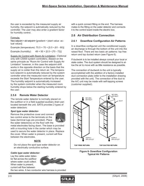
<strong>Mini</strong>-<strong>Space</strong> <strong>Series</strong> <strong>Installation</strong>, <strong>Operation</strong> & <strong>Maintenance</strong> <strong>Manual</strong>2-5the user is exceeded by the measured supply airhumidity, the setpoint is autimatically reduced by thecontroller. The user may also enter a gradient factorfor humidity control.Formula:New setpoint = old setpoint+ [gradient • (start value -actualvalue)]Example (temperature): 70.5 = 70 + [0.5 • (61 - 60)]Example (humidity): 49 = 50 + [0.5 • (70 - 72)]Supply Air Control with Room Air Limitation- (Optionalonly with C5000 system controllers.) Based on thesame principle as “Room Air Control with Supply AirLimitation” however, in this case the setpoint shiftworks in the opposite direction on the basis that thesupply air is colder than the return air. The temperaturesetpoint is automatically reduced by the systemcontroller when the measured room air temperatureexceeds the Start Temperature entered by the user.The humidity setpoint is automatically increasedby the system controller when the measured roomhumidity drops below the starting humidity entered bythe user.2.5.6 Remote Water DetectorThe remote water detector is normally placed onthe subfloor or in a field supplied auxiliary drain panlocated beneath the unit. SATS provides 2 types ofwater detectors:Spot type water detector-Remove the protective cover and connecttwo control wires to the terminals on thebase (terminal lugs are provided). Placethe water detector(s) on the floor with themetal electrodes facing down. The base is providedwith a mounting hole in the center which may beused to secure the water detector in place. Replacethe cover. When water is present, current will flowbetween the electrodes.NOTEDo not place the spot type water detector onan electrically conductive surface.Cable type water detector-Lay the cable water detectorflat across the subfloorwhere water could collect.When water is present,current will flow betweenthe two wires. A two conductor wire harness is providedwith a quick connect fitting on the end. The harnessmates to the fitting on the water detector and connectsit to the control board inside the electric box.2.6 Air Distribution Connection2.6.1 Downflow Configuration Air PatternsIn a downfl ow configured unit the conditioned supplyair discharge is through the bottom of the unit into theraised floor. There are two basic air patterns: top freereturn and top ducted return (see Figure 6).If ductwork is to be installed always consult your local orstate codes. The duct system should be designed to allowthe air to move with as little resistance as possible.The connection of ductwork to the unit is typicallyaccomplished with the addition of a factory installedduct connection plate (refer to the installation drawingprovided with the unit). The connection of the duct tothe A/C unit may be made with self-tapping screws(customer supplied).RETURNAIR INLETTOP FREE RETURNSUPPLYAIR OUTLETRETURNAIR INLETSUPPLYAIR OUTLETTOP DUCTED RETURNFigure 6- Downflow ConfigurationTypical Air PatternsDUCT(©April, 2008)Air Technology Systems, Inc.