Mini-Space Series Installation, Operation & Maintenance Manual
Mini-Space Series Installation, Operation & Maintenance Manual
Mini-Space Series Installation, Operation & Maintenance Manual

You also want an ePaper? Increase the reach of your titles
YUMPU automatically turns print PDFs into web optimized ePapers that Google loves.
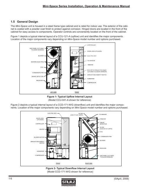
<strong>Mini</strong>-<strong>Space</strong> <strong>Series</strong> <strong>Installation</strong>, <strong>Operation</strong> & <strong>Maintenance</strong> <strong>Manual</strong>1.5 General DesignThe <strong>Mini</strong>-<strong>Space</strong> unit is housed in a steel frame type cabinet and is rated for indoor use. The exterior of the cabinetis coated with a powder coat finish to protect against corrosion. Hinged doors are located in the front of thecabinet for easy access to components. Operator controls are conveniently located on the front of the cabinet.Figure 1 depicts a typical internal layout of a CCU-121-A (upfl ow) unit and identifi es the major components.Location of the major components vary depending on <strong>Mini</strong>-<strong>Space</strong> model number and options purchased.CONTROLLERSIDE PANEL (CUT-AWAYTO SHOW INTERIOR)DOOR LOCK (2 PLACES)BLOWERELECTRIC BOXHEATERS (ELECTRIC)T/H SENSORFIRESTATCOILCONDENSATE PANSMOKE DETECTORRECEIVERPOP-OFF FILTER/ACCESS PANEL(CUT-AWAY TO SHOW INTERIOR)SERVICE DISCONNECT SWITCHHUMIDIFIERCOMPRESSORLEFT SIDEFRONTFigure 1- Typical Upflow Internal Layout(Model CCU-041-A shown for reference)Figure 2 depicts a typical internal layout of a CCD-171-W/G (downflow) unit and identifi es the major components.Location of the major components vary depending on <strong>Mini</strong>-<strong>Space</strong> model number and options purchased.ELECTRIC BOXFILTER(CCD-171-201 UNITS)T/H SENSORDOOR LOCK(2 PLACES)CONTROLLERHEATERFIRESTATSMOKEDETECTORFILTER(CCD-041/121 UNITS)COILBLOWER MOTORSERVICE DISCONNECTSWITCHCONDENSATE PANBLOWERRECEIVERHUMIDIFIERCOMPRESSORSIDE PANEL (CUT-AWAYTO SHOW INTERIOR)FRONTRIGHT SIDEFigure 2- Typical Downflow Internal Layout(Model CCD-171-W/G shown for reference)1-6(©April, 2008)Air Technology Systems, Inc.