Mini-Space Series Installation, Operation & Maintenance Manual
Mini-Space Series Installation, Operation & Maintenance Manual
Mini-Space Series Installation, Operation & Maintenance Manual

Create successful ePaper yourself
Turn your PDF publications into a flip-book with our unique Google optimized e-Paper software.
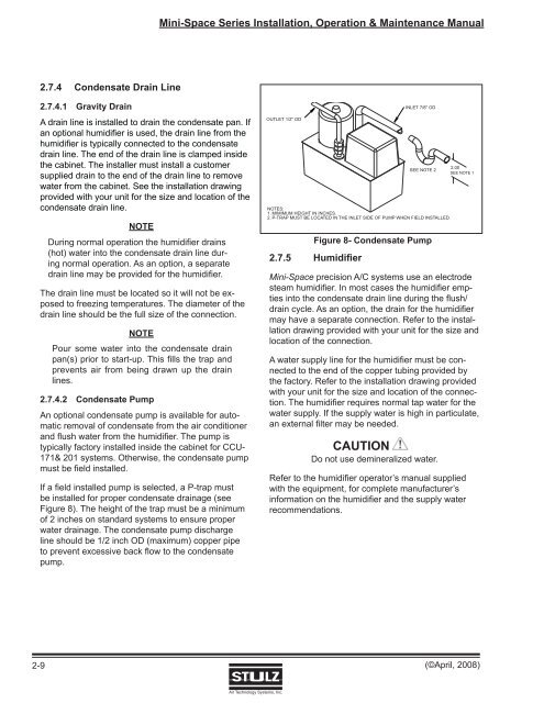
<strong>Mini</strong>-<strong>Space</strong> <strong>Series</strong> <strong>Installation</strong>, <strong>Operation</strong> & <strong>Maintenance</strong> <strong>Manual</strong>2.7.4 Condensate Drain Line2.7.4.1 Gravity DrainA drain line is installed to drain the condensate pan. Ifan optional humidifi er is used, the drain line from thehumidifier is typically connected to the condensatedrain line. The end of the drain line is clamped insidethe cabinet. The installer must install a customersupplied drain to the end of the drain line to removewater from the cabinet. See the installation drawingprovided with your unit for the size and location of thecondensate drain line.NOTEDuring normal operation the humidifier drains(hot) water into the condensate drain line duringnormal operation. As an option, a separatedrain line may be provided for the humidifier.The drain line must be located so it will not be exposedto freezing temperatures. The diameter of thedrain line should be the full size of the connection.NOTEPour some water into the condensate drainpan(s) prior to start-up. This fi lls the trap andprevents air from being drawn up the drainlines.2.7.4.2 Condensate PumpAn optional condensate pump is available for automaticremoval of condensate from the air conditionerand flush water from the humidifier. The pump istypically factory installed inside the cabinet for CCU-171& 201 systems. Otherwise, the condensate pumpmust be field installed.If a field installed pump is selected, a P-trap mustbe installed for proper condensate drainage (seeFigure 8). The height of the trap must be a minimumof 2 inches on standard systems to ensure properwater drainage. The condensate pump dischargeline should be 1/2 inch OD (maximum) copper pipeto prevent excessive back flow to the condensatepump.OUTLET 1/2" OD2.7.5 HumidifierINLET 7/8" ODSEE NOTE 2NOTES:1. MIMIMUM HEIGHT IN INCHES.2. P-TRAP MUST BE LOCATED IN THE INLET SIDE OF PUMP WHEN FIELD INSTALLED.Figure 8- Condensate Pump<strong>Mini</strong>-<strong>Space</strong> precision A/C systems use an electrodesteam humidifi er. In most cases the humidifi er emptiesinto the condensate drain line during the fl ush/drain cycle. As an option, the drain for the humidifi ermay have a separate connection. Refer to the installationdrawing provided with your unit for the size andlocation of the connection.A water supply line for the humidifi er must be connectedto the end of the copper tubing provided bythe factory. Refer to the installation drawing providedwith your unit for the size and location of the connection.The humidifi er requires normal tap water for thewater supply. If the supply water is high in particulate,an external fi lter may be needed.CAUTIONDo not use demineralized water.2.00SEE NOTE 1Refer to the humidifi er operator’s manual suppliedwith the equipment, for complete manufacturer’sinformation on the humidifi er and the supply waterrecommendations.2-9(©April, 2008)Air Technology Systems, Inc.