Timing and Transients in Digital Circuits - Integrated Systems ...
Timing and Transients in Digital Circuits - Integrated Systems ...
Timing and Transients in Digital Circuits - Integrated Systems ...

You also want an ePaper? Increase the reach of your titles
YUMPU automatically turns print PDFs into web optimized ePapers that Google loves.
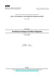
Institut für Integrierte Systeme<strong>Integrated</strong> <strong>Systems</strong> LaboratoryDepartment of Information Technology <strong>and</strong> Electrical Eng<strong>in</strong>eer<strong>in</strong>gVLSI I: von Architekturzu hoch<strong>in</strong>tegrierter Schaltung und FPGA227-0116-00LExercise 1<strong>Tim<strong>in</strong>g</strong> <strong>and</strong> <strong>Transients</strong> <strong>in</strong> <strong>Digital</strong> <strong>Circuits</strong>Prof. Dr. H. Kaesl<strong>in</strong>Dr. N. FelberSVN Rev.: 675Last Changed: 29-02-2012Rem<strong>in</strong>der:With the execution of this tra<strong>in</strong><strong>in</strong>g you declare that you underst<strong>and</strong> <strong>and</strong> accept the regulations aboutus<strong>in</strong>g CAE/CAD software <strong>in</strong>stallations at the ETH Zurich. These regulations can be read anytime athttp://dz.ee.ethz.ch/regulations/<strong>in</strong>dex.en.html.
1 What you will learnComputer science views digital circuits as ideal mach<strong>in</strong>es <strong>and</strong> describes their behavior us<strong>in</strong>g mathematicalmodels such as f<strong>in</strong>ite state mach<strong>in</strong>es <strong>and</strong> computer arithmetics. While such abstractions arevalid <strong>and</strong> useful given certa<strong>in</strong> preconditions, they omit a number of effects that impact real circuits.The most important simplifications relate to transients <strong>and</strong> delays that come from the fact that noelectrical node can change its state <strong>in</strong> zero time <strong>and</strong> no physical signal can propagate <strong>in</strong> zero time.Gett<strong>in</strong>g the tim<strong>in</strong>g right is absolutely essential when design<strong>in</strong>g a digital circuit, if that circuit is meant tobehave <strong>in</strong> the same way as its mathematical or computer model. Several lessons of our VLSI coursewill be devoted to data throughput, tim<strong>in</strong>g constra<strong>in</strong>ts, tradeoffs between time <strong>and</strong> energy, clock<strong>in</strong>gdiscipl<strong>in</strong>es, sychronization, metastability, <strong>and</strong> other tim<strong>in</strong>g-related issues.This warm-up exercise is here to make sure you are aware of the fundamental concepts <strong>and</strong> quantitiesrequired to underst<strong>and</strong> that material <strong>and</strong> to become an expert user of electronic design automation(EDA) software. More specifically, we will show you• How to capture the time-wise behavior of digital (sub)circuits.• Visual formalisms that help analyze tim<strong>in</strong>g issues.• The very basics of synchronous circuit operation <strong>and</strong> simulation set up.• What determ<strong>in</strong>es the maximum frequency at which a circuit can be clocked.• The dependencies <strong>in</strong>troduced by signals enter<strong>in</strong>g or depart<strong>in</strong>g from a circuit.• Th<strong>in</strong>gs to watch out for when design<strong>in</strong>g control logic <strong>and</strong> state mach<strong>in</strong>es.2 Terms <strong>and</strong> Concepts2.1 <strong>Transients</strong> <strong>in</strong> digital circuitsAll circuits discussed here are digital <strong>and</strong> make use of two-valued signals. For practical reasons,the voltage levels that represent 0 <strong>and</strong> 1 respectively must be separated by some “forbidden” <strong>in</strong>tervalwhere a signal has no mean<strong>in</strong>gful b<strong>in</strong>ary <strong>in</strong>terpretation <strong>and</strong> must be considered as logically undef<strong>in</strong>edor <strong>in</strong>valid. In accordance with the IEEE 1164 st<strong>and</strong>ard, we use the symbol X to denote situationswhere a signal is electrically driven but has no known logic value. Note that any signal that switchesfrom 0 to 1 or vice versa will transit through the forbidden <strong>in</strong>terval for a brief lapse of time.Some signals may even rock back <strong>and</strong> forth a few times or exihibit short-lived voltage excursionsbefore eventually reach<strong>in</strong>g their steady-state condition. As expla<strong>in</strong>ed <strong>in</strong> appendix A.5 “Transient behaviorof logic circuits” of our textbook 1 even circuits of just a few gates must be suspected to developsuch spurious <strong>and</strong> unwanted signals, known as hazards, unless one has proof to the contrary.2.2 Comb<strong>in</strong>ational, sequential, <strong>and</strong> sychronous circuitsA digital circuit is qualified as comb<strong>in</strong>ational if its present output gets determ<strong>in</strong>ed by its present<strong>in</strong>put exclusively when <strong>in</strong> steady-state condition. This contrasts with sequential logic the output ofwhich depends not only on present but also on past <strong>in</strong>put values. Sequential circuits must, therefore,necessarily keep their state <strong>in</strong> some k<strong>in</strong>d of storage elements whereas comb<strong>in</strong>ational ones have no1Hubert Kaesl<strong>in</strong>, “<strong>Digital</strong> <strong>Integrated</strong> Circuit Design, from VLSI Architectures to CMOS Fabrication”, CambridgeUniversity Press, 2008.2
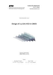
state. This is why the former are also referred to as state-hold<strong>in</strong>g or as memoriz<strong>in</strong>g, <strong>and</strong> the latteras state-less or as memoryless.Sequential networks typically consist of comb<strong>in</strong>ational gates <strong>and</strong> storage elements (such as flip-flops,latches, <strong>and</strong>/or some memory). Their correct operation critically depends on proper tim<strong>in</strong>g, that is onconsistently respect<strong>in</strong>g all time-related conditions imposed by the various circuit components.As you will learn, synchronous circuits where all state transitions are triggered by one particularperiodic signal, called clock, are easier to design <strong>and</strong> safer to operate than asynchronous circuitswhere there is no (global) clock <strong>and</strong> where state transitions may occur at any time, e.g. <strong>in</strong> responseto some unanticipated hazard. We will consider synchronous circuits exclusively <strong>in</strong> this exercise.2.3 Basic tim<strong>in</strong>g quantitiesAs becomes clear from fig.1 <strong>and</strong> from the table below, it takes two tim<strong>in</strong>g quantities to capture thetime-wise behavior of comb<strong>in</strong>ational circuits. An additional six are required for flip-flops, latches, <strong>and</strong>memories. 2 t su fft pd ffa)Comb<strong>in</strong>ationalLogicXXFFt cd ct pd ct cd ct pd cb) Flip-Flopt ho ffCLKt clk fat clk riDpositive edgetriggeredQt cd ffc)LatchCLKDt su lat ho lapassholdt clk hit clk hi t clk lot clk riCLKDQCLKt clk lot clk faDQCLK to Q D to Qpasses while highholds while lowQt cd lct pd lct cd ldt pd ldFigure 1: <strong>Tim<strong>in</strong>g</strong> characteristics of comb<strong>in</strong>ational subcircuits (a), flip-flops (b), <strong>and</strong> latches (c).2Actually, there are two more, called recovery time <strong>and</strong> home time, required to model asychronous (re)set <strong>in</strong>puts,but we will skip them at this po<strong>in</strong>t.3
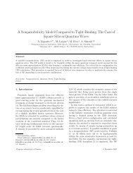
i(k)present<strong>in</strong>putcomb<strong>in</strong>ationalcircuitryt iot soo(k)presentoutputactive clock edget su t ho of stateregistersymbolsstimulus applicationt sst isresponse acquisitions(k)presentstatestate registers(k+1)nextstatet ist sst sorecord<strong>in</strong>g of valuesactive clock edgepassive clock edgea)CLKresponseacquisitiont iostimulusapplicationc)t sst sot ist ioo(k −1)s(k)s(k+1)i(k) o(k) i(k+1) o(k+1)i(k+2)timesignaturesdata valid "0" or "1"CLKclock signaldata <strong>in</strong>validor unknown "X"i(.)<strong>in</strong>puthigh impedance "Z"o(.)outputdon’t care "−"b)Figure 2: Different views on circuit delays <strong>and</strong> tim<strong>in</strong>g. Signal propagation paths <strong>in</strong> a synchronouscircuit (a), tim<strong>in</strong>g diagram (b), Anceau diagram (c).5
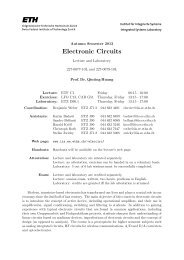
For reasons expla<strong>in</strong>ed <strong>in</strong> appendix 3.7 “Deriv<strong>in</strong>g a coherent schedule for simulation <strong>and</strong> test” of ourtextbook, we strongly recommend to have these events occur <strong>in</strong> a strictly periodic fashion <strong>and</strong> toorder them as follows △ ↓ (⊤ = □) ↑ . Each clock period thus gets subdivided <strong>in</strong>to four phases. Ast<strong>and</strong>ard setup for a symmetric clock of 10 MHz is given below as an example.cycle events with times of occurrence [ns]k △ ↓ ⊤□ ↑0 10 50 90 1001 110 150 190 2002 210 250 290 300... ... ... ... ...2.6 <strong>Tim<strong>in</strong>g</strong> diagramsDiagrams help to underst<strong>and</strong> the events <strong>and</strong> activities that occur dur<strong>in</strong>g circuit operation <strong>and</strong> to capturetheir respective cause ↦→ effect <strong>and</strong>/or precedence relationships. The most popular form is the(l<strong>in</strong>ear) tim<strong>in</strong>g diagram, shown <strong>in</strong> the lower half of fig.2b below the time axis. Here the waveformsobserved at the circuit p<strong>in</strong>s are reproduced a bit like on an oscilloscope. In addition, a few signatureshelp to express special data conditions such as <strong>in</strong>valid or unknown output X, a high impedancecondition Z, <strong>and</strong> a don’t care <strong>in</strong>put -.The upper half of fig.2b relates the waveforms of tim<strong>in</strong>g diagram to the timewise separations betweenthe various periodic events <strong>in</strong> each clock cycle required to ensure proper circuit operation. Note thetwo short <strong>and</strong> fat vertical bars. The lower one <strong>in</strong>dicates when the output has settled to a new value<strong>and</strong> becomes available for data acquisition. Similarly, the upper bar tells when the computation of thenext state has come to an end <strong>and</strong> so determ<strong>in</strong>es the earliest po<strong>in</strong>t <strong>in</strong> time the circuit may be safelyclocked. Each bar can be understood as a maximum-<strong>in</strong>-time or “whichever comes later” operator.As circuit operation is periodic, there is noth<strong>in</strong>g more natural than us<strong>in</strong>g a circular arrangement torepresent the sequence of events <strong>and</strong> their time-wise relationships. This k<strong>in</strong>d of graph is known asAnceau diagram after its <strong>in</strong>ventor François Anceau, see fig.2c.3 ExercisesThe simplest <strong>and</strong> most common clock<strong>in</strong>g discipl<strong>in</strong>e is edge-triggered one-phase clock<strong>in</strong>g. All registersare built from flip-flops exclusively <strong>and</strong> all flip-flops may change state either at the ris<strong>in</strong>g or at thefall<strong>in</strong>g edge of the clock, that is once per clock period. In this exercise we presuppose this clock<strong>in</strong>gscheme with a duty cycle of 50%. However, to solve some specific problems, you are free to consideralternative approaches.3.1 <strong>Tim<strong>in</strong>g</strong> verificationExercise 1 : Introductory exampleConsider the circuit <strong>in</strong> fig.3. t .. ff <strong>and</strong> t .. c st<strong>and</strong> for the tim<strong>in</strong>g quantities of the registers <strong>and</strong> comb<strong>in</strong>ationalcells respectively. Clock distribution is assumed to be perfect with no delay or skew t sk = 0.6
tpd ff, tcd fftsu ff, tho fftpd ff, tcd fftsu ff, tho ffDBU1QB DA QAtpd c, tcd cU2ClkxCtskFigure 3: Synchronous sequential circuit.a) What is the function of this circuit?b) State the basic tim<strong>in</strong>g requirements <strong>in</strong> mathematical terms!c) For a given t ho ff , which tim<strong>in</strong>g condition is most critical to ensure proper operation? What canyou do to alleviate this requirement?d) Assume an extremely long clock high time t hi clk . Is it possible to replace the D-type flip-flopswith D-type latches? Note from fig.1 that st<strong>and</strong>ard D-type latches are transparent while theclock is 1. Expla<strong>in</strong> how you have arrived at your conclusion!e) For t cd c = t pd c <strong>and</strong> with t ho la be<strong>in</strong>g given, what is the condition that t hi clk must satisfy whenboth flip-flops are replaced by latches? Draw a tim<strong>in</strong>g or Anceau diagram!Exercise 2 : <strong>Tim<strong>in</strong>g</strong> <strong>in</strong> a l<strong>in</strong>ear feedback shift registerL<strong>in</strong>ear feedback shift registers (LFSR) are typically used for generat<strong>in</strong>g sequences, e.g. for cyclicencod<strong>in</strong>g or for generat<strong>in</strong>g pseudo-r<strong>and</strong>om numbers. As an example, fig.4 shows a circuit wired forCRC-4 encod<strong>in</strong>g.InxSIU4D Q U5 D Q D Q D QU3U2 U1 U0ClkxCQ3xSO Q2xSO Q1xSO Q0xSOFigure 4: Cyclic coder circuitAssume the tim<strong>in</strong>g data below apply:Flip-flops: t pd ff = t cd ff = 0.9 ns, t su ff = 0.5 ns, t ho ff = 0.2 nsXOR gates: t pd c = t cd c = 0.8 nsa) Determ<strong>in</strong>e the set of signal propagation paths for this circuit accord<strong>in</strong>g to fig.2a!b) Draw an Anceau diagram or a tim<strong>in</strong>g diagram for a clock period of T clk = 4.0 ns!c) Determ<strong>in</strong>e the maximum admissible clock speed for this circuit!7
d) Specify the valid time w<strong>in</strong>dows for stimulus application △ <strong>and</strong> for response acquisition ⊤ whenthe circuit is clocked at maximum rate!e) Def<strong>in</strong>e the <strong>in</strong>terface tim<strong>in</strong>g parameters t pd , t su , t ho that apply when the time-wise behavior ofthis circuit is viewed from externally!Exercise 3 : Composite circuitsAs opposed to what fig.2a might suggest, digital circuits other than toy examples are not organized asone large state mach<strong>in</strong>e but composed from smaller subcircuits <strong>and</strong> automata that exchange signalsto coord<strong>in</strong>ate overall operation. This simplifies functional verification <strong>and</strong> makes it possible to takeadvantage of specialized <strong>and</strong> efficient build<strong>in</strong>g blocks such as ROMs, ALUs, etc. Let us focus on thedata exchange at the <strong>in</strong>terface between two such subcircuits as shown <strong>in</strong> fig.5.ABU11U1x 1U3U8U9U10ROMA5 D7U12U6U2clkU4U5CLOCK TREEU7tclk cycleclkaddressdatatclk hightsu ROM tho ROMaddress validtpd ROMprevious datatclk lowdata validFigure 5: Composite circuit (top), tim<strong>in</strong>g diagram of the ROM (bottom)The entire circuit runs with a clock period of T clk = 11 ns <strong>and</strong> the tim<strong>in</strong>g parameters of its variouscomponents are as follows.Subcircuit ARegister: t pd ff = t cd ff = 0.9 ns, t su = 0.5 ns, t ho = 0.0 ns.Buffer U2: t pd c = t cd c = 0.8 ns.Subcircuit BRegisters: t pd ff = t cd ff = 0.9 ns, t su = 0.5 ns, t ho = 0.0 ns.Comb<strong>in</strong>ational components (buffers, <strong>in</strong>verter, adder): t pd c = t cd c = 0.8 ns.ROM: t su ROM = 0.0 ns, t ho ROM = 2.3 ns, t pd ROM = 7 ns, see fig.5 for further details.a) Determ<strong>in</strong>e the external <strong>in</strong>terface tim<strong>in</strong>g parameters t su B , t ho B , t cd A , t pd A !8
) Are there any problems related to the <strong>in</strong>terface of the two subcircuits? Check the setup <strong>and</strong>hold marg<strong>in</strong>s!c) Verify the <strong>in</strong>ternal tim<strong>in</strong>g constra<strong>in</strong>ts for subcircuit B. The tim<strong>in</strong>g behavior of complex build<strong>in</strong>gblocks (such as ALUs) or macrocells (such as RAMs <strong>and</strong> ROMs) often differs significantly fromthat of elementary gates or flip-flops. Do you see any problems <strong>in</strong> subcircuit B?d) F<strong>in</strong>d solutions to solve the problems, if any,◦ by add<strong>in</strong>g comb<strong>in</strong>ational cells exclusively,◦ by add<strong>in</strong>g different storage elements!Which solution do you prefer?3.2 Design of safe f<strong>in</strong>ite state mach<strong>in</strong>esThis section extends our considerations to f<strong>in</strong>ite state mach<strong>in</strong>es <strong>and</strong> to circuits where a state mach<strong>in</strong>econtrols other parts of the circuit such as a datapath. If you lack the necessary background tounderst<strong>and</strong> <strong>and</strong> solve the problems, you may want to consult appendix B “F<strong>in</strong>ite State Mach<strong>in</strong>es” <strong>in</strong>our textbook to learn more about the various types of automata <strong>and</strong> how the compare.Exercise 4 : Automata types <strong>and</strong> their propertiesa) Which class of f<strong>in</strong>ite state mach<strong>in</strong>es does the circuit of fig.3 belong to? Expla<strong>in</strong> why!b) What is the latency of this circuit?c) Can it possibly develop hazards at the output?d) Answer the same questions for the circuit of fig.4!Exercise 5 : Parasitic <strong>in</strong>puts <strong>and</strong> cyclesYour are tasked with devis<strong>in</strong>g a controller for a semi-automatic gear unit. States are low gear, secondgear, top gear, reverse gear, <strong>and</strong> neutral. There are two separate <strong>in</strong>put signals, namely UpxSI <strong>and</strong>DownxSI.a) Capture the desired functionality <strong>in</strong> a state diagram!b) Complete that state diagram to make your design fault-tolerant! This means you must not onlyconsider the regular states <strong>and</strong> <strong>in</strong>puts, but the parasitic states (states which are present <strong>in</strong> ab<strong>in</strong>ary representation but unused) <strong>and</strong> all physically possible <strong>in</strong>put comb<strong>in</strong>ations too.c) Pick a mean<strong>in</strong>gful reset state!9
<strong>in</strong>outcontroller1a b cU1U2U3U4controller2Figure 6: Two cross-connected state mach<strong>in</strong>esExercise 6 : Interact<strong>in</strong>g state mach<strong>in</strong>esConsider the circuit of fig.6.a) What problems may arise when these two automata are connected together?b) Solve this problem by add<strong>in</strong>g additional components to controller2!c) What type of state mach<strong>in</strong>e should be used for controller1 to avoid complications?10