


You also want an ePaper? Increase the reach of your titles
YUMPU automatically turns print PDFs into web optimized ePapers that Google loves.
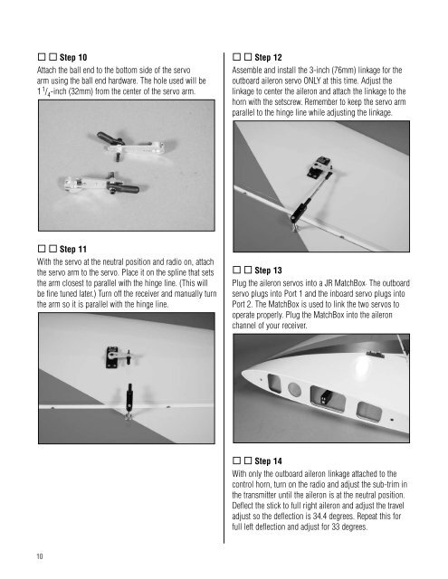
Step 10Attach the ball end to the bottom side of the servoarm using the ball end hardware. The hole used will be1 1 / 4-inch (32mm) from the center of the servo arm. Step 12Assemble and install the 3-inch (76mm) linkage for theoutboard aileron servo ONLY at this time. Adjust thelinkage to center the aileron and attach the linkage to thehorn with the setscrew. Remember to keep the servo armparallel to the hinge line while adjusting the linkage. Step 11With the servo at the neutral position and radio on, attachthe servo arm to the servo. Place it on the spline that setsthe arm closest to parallel with the hinge line. (This willbe fine tuned later.) Turn off the receiver and manually turnthe arm so it is parallel with the hinge line. Step 13Plug the aileron servos into a JR MatchBox. The outboardservo plugs into Port 1 and the inboard servo plugs intoPort 2. The MatchBox is used to link the two servos tooperate properly. Plug the MatchBox into the aileronchannel of your receiver. Step 14With only the outboard aileron linkage attached to thecontrol horn, turn on the radio and adjust the sub-trim inthe transmitter until the aileron is at the neutral position.Deflect the stick to full right aileron and adjust the traveladjust so the deflection is 34.4 degrees. Repeat this forfull left deflection and adjust for 33 degrees.10


