Palair Plus - Ingersoll Rand Industrial Technologies On-line ...
Palair Plus - Ingersoll Rand Industrial Technologies On-line ...
Palair Plus - Ingersoll Rand Industrial Technologies On-line ...

You also want an ePaper? Increase the reach of your titles
YUMPU automatically turns print PDFs into web optimized ePapers that Google loves.
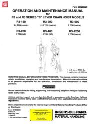
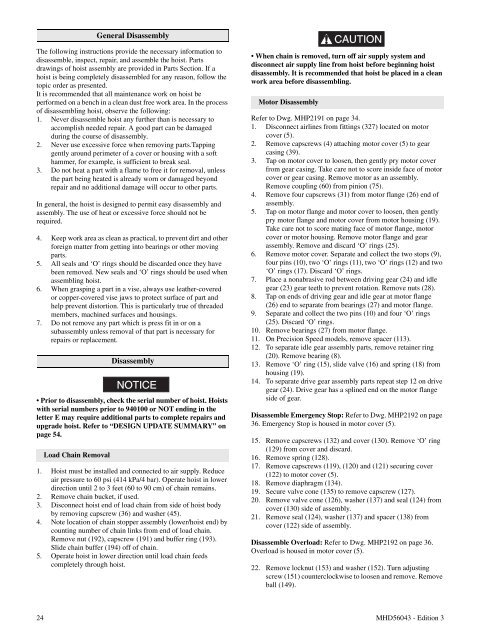
General DisassemblyThe following instructions provide the necessary information todisassemble, inspect, repair, and assemble the hoist. Partsdrawings of hoist assembly are provided in Parts Section. If ahoist is being completely disassembled for any reason, follow thetopic order as presented.It is recommended that all maintenance work on hoist beperformed on a bench in a clean dust free work area. In the processof disassembling hoist, observe the following:1. Never disassemble hoist any further than is necessary toaccomplish needed repair. A good part can be damagedduring the course of disassembly.2. Never use excessive force when removing parts.Tappinggently around perimeter of a cover or housing with a softhammer, for example, is sufficient to break seal.3. Do not heat a part with a flame to free it for removal, unlessthe part being heated is already worn or damaged beyondrepair and no additional damage will occur to other parts.In general, the hoist is designed to permit easy disassembly andassembly. The use of heat or excessive force should not berequired.4. Keep work area as clean as practical, to prevent dirt and otherforeign matter from getting into bearings or other movingparts.5. All seals and ‘O’ rings should be discarded once they havebeen removed. New seals and ‘O’ rings should be used whenassembling hoist.6. When grasping a part in a vise, always use leather-coveredor copper-covered vise jaws to protect surface of part andhelp prevent distortion. This is particularly true of threadedmembers, machined surfaces and housings.7. Do not remove any part which is press fit in or on asubassembly unless removal of that part is necessary forrepairs or replacement.DisassemblyNOTICE• Prior to disassembly, check the serial number of hoist. Hoistswith serial numbers prior to 940100 or NOT ending in theletter E may require additional parts to complete repairs andupgrade hoist. Refer to “DESIGN UPDATE SUMMARY” onpage 54.Load Chain Removal1. Hoist must be installed and connected to air supply. Reduceair pressure to 60 psi (414 kPa/4 bar). Operate hoist in lowerdirection until 2 to 3 feet (60 to 90 cm) of chain remains.2. Remove chain bucket, if used.3. Disconnect hoist end of load chain from side of hoist bodyby removing capscrew (36) and washer (45).4. Note location of chain stopper assembly (lower/hoist end) bycounting number of chain links from end of load chain.Remove nut (192), capscrew (191) and buffer ring (193).Slide chain buffer (194) off of chain.5. Operate hoist in lower direction until load chain feedscompletely through hoist.CAUTION• When chain is removed, turn off air supply system anddisconnect air supply <strong>line</strong> from hoist before beginning hoistdisassembly. It is recommended that hoist be placed in a cleanwork area before disassembling.Motor DisassemblyRefer to Dwg. MHP2191 on page 34.1. Disconnect air<strong>line</strong>s from fittings (327) located on motorcover (5).2. Remove capscrews (4) attaching motor cover (5) to gearcasing (39).3. Tap on motor cover to loosen, then gently pry motor coverfrom gear casing. Take care not to score inside face of motorcover or gear casing. Remove motor as an assembly.Remove coupling (60) from pinion (75).4. Remove four capscrews (31) from motor flange (26) end ofassembly.5. Tap on motor flange and motor cover to loosen, then gentlypry motor flange and motor cover from motor housing (19).Take care not to score mating face of motor flange, motorcover or motor housing. Remove motor flange and gearassembly. Remove and discard ‘O’ rings (25).6. Remove motor cover. Separate and collect the two stops (9),four pins (10), two ‘O’ rings (11), two ‘O’ rings (12) and two‘O’ rings (17). Discard ‘O’ rings.7. Place a nonabrasive rod between driving gear (24) and idlegear (23) gear teeth to prevent rotation. Remove nuts (28).8. Tap on ends of driving gear and idle gear at motor flange(26) end to separate from bearings (27) and motor flange.9. Separate and collect the two pins (10) and four ‘O’ rings(25). Discard ‘O’ rings.10. Remove bearings (27) from motor flange.11. <strong>On</strong> Precision Speed models, remove spacer (113).12. To separate idle gear assembly parts, remove retainer ring(20). Remove bearing (8).13. Remove ‘O’ ring (15), slide valve (16) and spring (18) fromhousing (19).14. To separate drive gear assembly parts repeat step 12 on drivegear (24). Drive gear has a sp<strong>line</strong>d end on the motor flangeside of gear.Disassemble Emergency Stop: Refer to Dwg. MHP2192 on page36. Emergency Stop is housed in motor cover (5).15. Remove capscrews (132) and cover (130). Remove ‘O’ ring(129) from cover and discard.16. Remove spring (128).17. Remove capscrews (119), (120) and (121) securing cover(122) to motor cover (5).18. Remove diaphragm (134).19. Secure valve cone (135) to remove capscrew (127).20. Remove valve cone (126), washer (137) and seal (124) fromcover (130) side of assembly.21. Remove seal (124), washer (137) and spacer (138) fromcover (122) side of assembly.Disassemble Overload: Refer to Dwg. MHP2192 on page 36.Overload is housed in motor cover (5).22. Remove locknut (153) and washer (152). Turn adjustingscrew (151) counterclockwise to loosen and remove. Removeball (149).24 MHD56043 - Edition 3