Palair Plus - Ingersoll Rand Industrial Technologies On-line ...
Palair Plus - Ingersoll Rand Industrial Technologies On-line ...
Palair Plus - Ingersoll Rand Industrial Technologies On-line ...

You also want an ePaper? Increase the reach of your titles
YUMPU automatically turns print PDFs into web optimized ePapers that Google loves.
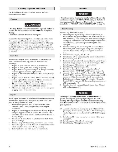
Cleaning, Inspection and RepairUse the following procedures to clean, inspect, and repaircomponents of the hoist.CleaningCAUTION• Bearings that are loose or worn must be replaced. Failure toobserve this precaution will result in additional componentdamage.• Do not use trichloroethylene to clean parts.Clean all hoist component parts in solvent (except for the brakedisc). Use of a stiff bristle brush will facilitate removal ofaccumulated dirt and sediments on gears and frames. If bushingshave been removed it maybe necessary to carefully scrape oldLoctite® from bearing bores. Dry each part using low pressure,filtered compressed air. If brake friction disc is oil soaked, it mustbe replaced.InspectionAll disassembled parts should be inspected to determine theirfitness for continued use. Pay particular attention to thefollowing:1. Inspect all gears for worn, cracked, or broken teeth.2. Inspect all bushings for wear, scoring, or galling.3. Inspect shafts for ridges caused by wear. If ridges caused bywear are apparent on shafts, replace shaft.4. Inspect all threaded items and replace those having damagedthreads.5. Inspect brake friction disc for oil. If brake friction disc is oilsoaked, replace brake friction disc. If brake friction disc isglazed, sand it lightly using fine emery cloth.6. Measure thickness of brake friction disc. If brake frictiondisc (88) is less than 0.098 in. (2.5 mm), replace.7. Check screen (33), filter (3) and silencer (37) for damage orclogging caused by excessive dirt.RepairActual repairs are limited to the removal of small burrs and otherminor surface imperfections from gears and shafts. Use a finestone or emery cloth for this work.1. Worn or damaged parts must be replaced. Refer to theapplicable Parts Listing for specific replacement partsinformation.2. Inspect all remaining parts for evidence of damage. Replaceor repair any part which is in questionable condition. Thecost of the part is often minor in comparison with the cost ofredoing the job.3. Smooth out all nicks, burrs, or galled spots on shafts, bores,pins, or bushings.4. Examine all gear teeth carefully, and remove nicks or burrs.5. Polish the edges of all shaft shoulders to remove small nickswhich may have been caused during handling.6. Remove all nicks and burrs caused by lockwashers.AssemblyNOTICE• Prior to assembly, check serial number of hoist. Hoists withserial numbers prior to 940100 or NOT ending in the letter Emay require additional parts to effect repairs and upgradehoist. Refer to “DESIGN UPDATE SUMMARY” on page 54.Hoist AssemblyRefer to Dwg. MHP1989 on page 32.1. Install ring (42) in gear casing (39) so it is positioned justbelow retainer ring groove on brake side. Install retainer ring(40). Tap bearing (43) into ring (42) from motor side of gearcasing (39). Extreme care is required during this operation toensure bearing (43) remains square and ring (42) is notdamaged.2. Install second ring (42) and bearing (43) on sprocket (63).Slide chain guide (50) into gear casing (39). Tap or presssprocket (63) assembly into gear casing (39) from motorside.3. Install retainer ring (40) at motor side.4. Install shafts (34) in gear casing (39). Ensure shafts locate inholes in chain guide (50).5. Position hoist vertically with motor end down. Lubricate andinstall ‘O’ ring (64) in groove on outside of ring gear (65).Install ring gear (65) on sp<strong>line</strong> of sprocket (63).6. Install bearing (66) on sprocket (63).7. Install load chain. Refer to ‘Load Chain Installation’procedures in the “MAINTENANCE” section on page 28.8. Assemble chain guide stop (53) to chain holder (54). ApplyLoctite® 243 to capscrew (58) threads and secure parts withcapscrews (58) and washers (56). Install assembled chainholder in bottom of gear casing (39) with pins (46). ApplyLoctite® 243 to capscrew (52) threads and tighten capscrews(52) to secure pins (46).9. Install pinion (75), bearing (80), and retainer rings (70) and(82) in planet carrier (67).NOTICE• Planet gear assembly maintenance should be limited togeneral cleaning and greasing of planet gears (69) andbearings (68). If planet gear assembly was removed duringhoist disassembly it will be necessary to correctly adjust planetgear alignment.10. Assemble planet assembly so planet gears (69) mesh withpinion (75). Position planet gears (69) so “0” marks engravedon planet gears are in <strong>line</strong>. Refer to Dwg. MHP0242 on page27.11. Install assembled planet assembly with pinion (75) in gearcasing (39).12. Install ring gear (76) with notches outward.13. Install bearing (78) on planet carrier (67).26 MHD56043 - Edition 3