Palair Plus - Ingersoll Rand Industrial Technologies On-line ...
Palair Plus - Ingersoll Rand Industrial Technologies On-line ...
Palair Plus - Ingersoll Rand Industrial Technologies On-line ...

You also want an ePaper? Increase the reach of your titles
YUMPU automatically turns print PDFs into web optimized ePapers that Google loves.
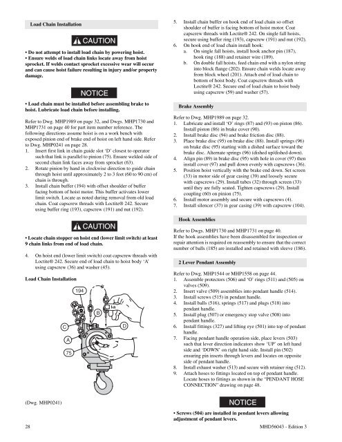
Load Chain InstallationCAUTION• Do not attempt to install load chain by powering hoist.• Ensure welds of load chain links locate away from hoistsprocket. If welds contact sprocket excessive wear will occurand can cause hoist failure resulting in injury and/or propertydamage.NOTICE• Load chain must be installed before assembling brake tohoist. Lubricate load chain before installing.Refer to Dwg. MHP1989 on page 32, and Dwgs. MHP1730 andMHP1731 on page 40 for part item number reference. Thefollowing directions assume hoist is on a work bench withexposed pinion end of brake end of hoist on left hand side. Referto Dwg. MHP0241 on page 28.1. Insert first link in chain guide slot ‘D’ closest to operatorsuch that link is parallel to pinion (75). Ensure welded side ofsecond chain link faces away from sprocket (63).2. Rotate pinion by hand in clockwise direction to guide chainthrough hoist until approximately 2 to 3 feet (60 to 90 cm) ofchain is through.3. Install chain buffer (194) with offset shoulder of bufferfacing bottom of hoist motor. This buffer activates lowerlimit switch. Locate as noted during removal from old loadchain. Coat capscrew threads with Loctite® 242. Secureusing buffer ring (193), capscrew (191) and nut (192).CAUTION• Locate chain stopper on hoist end (lower limit switch) at least9 chain links from end of load chain.4. <strong>On</strong> hoist end (lower limit switch) coat capscrew threads withLoctite® 242. Secure end of load chain to hoist body ‘A’using capscrew (36) and washer (45).Load Chain Installation5. Install chain buffer on hook end of load chain so offsetshoulder of buffer is facing bottom of hoist motor. Coatcapscrew threads with Loctite® 242. <strong>On</strong> single fall hoists,secure using buffer ring (193), capscrew (191) and nut (192).6. <strong>On</strong> hook end of load chain install hook:a. <strong>On</strong> single fall hoists, install hook anchor pin (187),hook ring (188) and retainer wire (189).b. <strong>On</strong> double fall hoists, feed chain end with a nylon stringinto block flange (202). Ensure chain welds locate awayfrom block wheel (201). Attach end of load chain tobottom of hoist body. Coat capscrew threads withLoctite® 242. Secure end of load chain to hoist bodyusing capscrew (59) and washer (57).Brake AssemblyRefer to Dwg. MHP1989 on page 32.1. Lubricate and install ‘O’ rings (87) and (93) on piston (86).Install piston (86) in brake cover (90).2. Install brake disc (94) and brake friction disc (88).3. Place brake disc (95) on brake disc (88). Install springs (96)on brake disc (95) starting with a dished surface toward thebrake disc. Alternate springs (96) (dished up/dished down).4. Align pin (89) in brake disc (95) with hole in cover (97) theninstall cover (97) and pull down evenly with capscrews (36).5. Position hoist vertically with the brake end down. Set screen(33) in motor side of gear casing (39) and loosely securewith capscrews (29). Install tubes (32) through screen (33)until they are fully seated. Tighten capscrews (29). Installcoupling (60) on pinion (75).6. Install motor assembly and secure with capscrews (4).7. Install silencer (37) in gear casing (39) with capscrew (104).Hook AssembliesRefertoDwgs.MHP1730andMHP1731onpage40.If the hook assemblies have been disassembled for inspection orrepair attention is required on reassembly to ensure that the correctnumber of balls (185) are installed and retained with sleeve (186).2 Lever Pendant AssemblyRefertoDwg.MHP1544orMHP1558onpage44.1. Assemble protectors (506) and ‘O’ rings (511) and (505) onvalves (509).2. Insert valve (509) assemblies into pendant handle (514).3. Install screws (515) in pendant handle.4. Install balls (516), springs (517) and plugs (518) intopendant handle.5. Install plug (507) or emergency stop valve (508) intopendant handle.6. Install fittings (327) and lifting eye (501) into top of pendanthandle.7. Facing pendant handle operation side, place levers (503)such that lever direction indicators show ‘UP’ on left handside and ‘DOWN’ on right hand side. Install pin (502)ensuring pin inserts through levers and locates on oppositeside of pendant handle.8. Install exhaust washer (513) and secure with retainer ring (512).9. Attach hoses to fittings located on top of pendant handle.Locate hoses to fittings as shown in the “PENDANT HOSECONNECTION” drawing on page 48.(Dwg. MHP0241)NOTICE• Screws (504) are installed in pendant levers allowingadjustment of pendant levers.28 MHD56043 - Edition 3