GA-8I915ME Series - GIGABYTE
GA-8I915ME Series - GIGABYTE
GA-8I915ME Series - GIGABYTE
- No tags were found...

You also want an ePaper? Increase the reach of your titles
YUMPU automatically turns print PDFs into web optimized ePapers that Google loves.
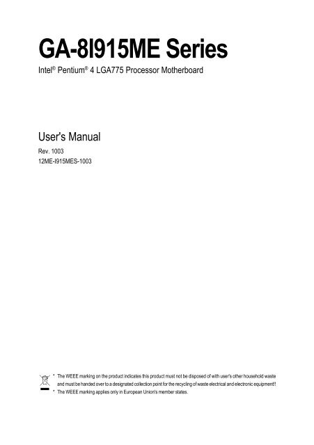
<strong>GA</strong>-<strong>8I915ME</strong> <strong>Series</strong>Intel ® Pentium ® 4 L<strong>GA</strong>775 Processor MotherboardUser's ManualRev. 100312ME-I915MES-1003* The WEEE marking on the product indicates this product must not be disposed of with user's other household wasteand must be handed over to a designated collection point for the recycling of waste electrical and electronic equipment!!* The WEEE marking applies only in European Union's member states.
Motherboard<strong>GA</strong>-<strong>8I915ME</strong>May 27, 2005Motherboard<strong>GA</strong>-<strong>8I915ME</strong>May 27, 2005
Copyright© 2005 GI<strong>GA</strong>-BYTE TECHNOLOGY CO., LTD. All rights reserved.The trademarks mentioned in the manual are legally registered to their respective companies.NoticeThe written content provided with this product is the property of Gigabyte.No part of this manual may be reproduced, copied, translated, or transmitted in any form or by anymeans without Gigabyte's prior written permission. Specifications and features are subject tochange without prior notice.Product Manual ClassificationIn order to assist in the use of this product, Gigabyte has categorized the user manual in thefollowing:• For detailed product information and specifications, please carefully read the"Product User Manual".• For detailed information related to Gigabyte's unique features, please go to "TechnologyGuide" section on Gigabyte's website to read or download the information you need.For more product details, please click onto Gigabyte's website at www.gigabyte.com.tw
Table of Content<strong>GA</strong>-<strong>8I915ME</strong> <strong>Series</strong> Motherboard Layout ...................................................................... 6Block Diagram ................................................................................................................ 7Chapter 1 Hardware Installation ..................................................................................... 91-1 Considerations Prior to Installation .................................................................... 91-2 Feature Summary .......................................................................................... 101-3 Installation of the CPU and Heatsink .............................................................. 121-3-1 Installation of the CPU ......................................................................................... 121-3-2 Installation of the Heatsink .................................................................................. 131-4 Installation of Memory .................................................................................... 141-5 Installation of Expansion Cards ...................................................................... 161-5-1 What is G.E.A.R.? ............................................................................................... 171-5-2 Graphics Card Support List ................................................................................ 171-6 I/O Back Panel Introduction ........................................................................... 201-7 Connectors Introduction .................................................................................. 21Chapter 2 BIOS Setup ................................................................................................ 33The Main Menu ......................................................................................................... 34(For example: <strong>GA</strong>-<strong>8I915ME</strong>-GV / BIOS Ver.: F2) ................................................... 342-1 Standard CMOS Features ............................................................................. 362-2 Advanced BIOS Features .............................................................................. 382-3 Integrated Peripherals ..................................................................................... 402-4 Power Management Setup ............................................................................. 422-5 PnP/PCI Configurations ................................................................................. 442-6 PC Health Status ........................................................................................... 442-7 Frequency/Voltage Control ............................................................................. 462-8 Load Fail-Safe Defaults ................................................................................... 472-9 Load Optimized Defaults ................................................................................. 472-10 Set Supervisor/User Password ..................................................................... 482-11 Save & Exit Setup ......................................................................................... 492-12 Exit Without Saving ....................................................................................... 49- 4 -
Chapter 3 Install Drivers ............................................................................................. 513-1 Install Chipset Drivers .................................................................................... 513-2 Software Applications ..................................................................................... 523-3 Driver CD Information .................................................................................... 523-4 Hardware Information ..................................................................................... 533-5 Contact Us ..................................................................................................... 53Chapter 4 Appendix .................................................................................................... 554-1 Unique Software Utilities ................................................................................ 554-1-1 EasyTune 5 Introduction ..................................................................................... 564-1-2 Xpress Recovery2 Introduction ........................................................................ 574-1-3 Flash BIOS Method Introduction ........................................................................ 604-1-4 2- / 4- / 6- Channel Audio Function Introduction ............................................ 694-1-5 Jack-Sensing Introduction .................................................................................. 754-2 Troubleshooting ............................................................................................... 77- 5 -
<strong>GA</strong>-<strong>8I915ME</strong> <strong>Series</strong> Motherboard LayoutKB_MSATX_12VCPU_FANIT8712FLPTCIV<strong>GA</strong>R_USBL<strong>GA</strong>775Intel 915GV<strong>GA</strong>-<strong>8I915ME</strong>ATXFDDUSBLANAUDIO1SUR_CENF_AUDIOCOM1SYS_FANRTL8100CRTL8110SPCIE_16PCI1GEARIntel 915GLIntel 910GLIntel 915GDIMM1ICH6DIMM2BIOSSATA2IDEBIOS_WP-GV-GL-C-GCODECPCI2SPDIF_IOCOM2WOLBUZZERF_USB1 F_USB2BATCLR_CMOSSATA0PWR_LEDCD_INAUX_INF_PANELOnly for <strong>GA</strong>-<strong>8I915ME</strong>-GV.Only for <strong>GA</strong>-<strong>8I915ME</strong>-GL.Only for <strong>GA</strong>-<strong>8I915ME</strong>-C.Only for <strong>GA</strong>-<strong>8I915ME</strong>-G.- 6 -
Block DiagramV<strong>GA</strong>L<strong>GA</strong>775ProcessorCPUCLK+/-(200 /133 MHz)PCI-ECLK(100MHz)HostInterfacePCI Express x16IntelIntel 915GVIntel 915GLIntel 910GLIntel 915GGMCHDDR400/333MHz DIMMDual Channel MemoryGMCHCLK (200/133MHz)66MHz33MHz14.318MHz48MHzPCI Express x4PCI BusIntelICH6BIOS2 Serial ATARTL8100CRTL8110SFloppy2 PCI1 G.E.A.R.RJ45AC97 LinkIT 8712FLPT PortCOM PortsAC97CODEC8 USBPorts24MHz33MHzPS/2 KB/MousePCICLK(33MHz)MICLine-OutLine-InSPDIF InSPDIF OutOnly for <strong>GA</strong>-<strong>8I915ME</strong>-GV.Only for <strong>GA</strong>-<strong>8I915ME</strong>-GL.Only for <strong>GA</strong>-<strong>8I915ME</strong>-C.Only for <strong>GA</strong>-<strong>8I915ME</strong>-G.(Note) <strong>GA</strong>-<strong>8I915ME</strong>-GV / <strong>GA</strong>-<strong>8I915ME</strong>-GL /<strong>GA</strong>-<strong>8I915ME</strong>-C supports transfer up toPCI Express x4 mode.<strong>GA</strong>-<strong>8I915ME</strong>-G supports transfer up toPCI Express x16 mode.- 7 -
- 8 -
Chapter 1 Hardware Installation1-1 Considerations Prior to InstallationPreparing Your ComputerThe motherboard contains numerous delicate electronic circuits and components which canbecome damaged as a result of electrostatic discharge (ESD). Thus, prior to installation, pleasefollow the instructions below:1. Please turn off the computer and unplug its power cord.2. When handling the motherboard, avoid touching any metal leads or connectors.3. It is best to wear an electrostatic discharge (ESD) cuff when handling electronic components(CPU, RAM).4. Prior to installing the electronic components, please have these items on top of an antistatic pad orwithin a electrostatic shielding container.5. Please verify that the power supply is switched off before unplugging the power supply connectorfrom the motherboard.EnglishInstallation Notices1. Prior to installation, please do not remove the stickers on the motherboard. These stickers are requiredfor warranty validation.2. Prior to the installation of the motherboard or any hardware, please first carefully read the informationin the provided manual.3. Before using the product, please verify that all cables and power connectors are connected.4. To prevent damage to the motherboard, please do not allow screws to come in contact with themotherboard circuit or its components.5. Please make sure there are no leftover screws or metal components placed on the motherboard orwithin the computer casing.6. Please do not place the computer system on an uneven surface.7. Turning on the computer power during the installation process can lead to damage to systemcomponents as well as physical harm to the user.8. If you are uncertain about any installation steps or have a problem related to the use of the product,please consult a certified computer technician.Instances of Non-Warranty1. Damage due to natural disaster, accident or human cause.2. Damage as a result of violating the conditions recommended in the user manual.3. Damage due to improper installation.4. Damage due to use of uncertified components.5. Damage due to use exceeding the permitted parameters.6. Product determined to be an unofficial Gigabyte product.- 9 -Hardware Installation
English1-2 Feature SummaryMotherboard • <strong>GA</strong>-<strong>8I915ME</strong> <strong>Series</strong> motherboard-<strong>GA</strong>-<strong>8I915ME</strong>-GV / <strong>GA</strong>-<strong>8I915ME</strong>-GL / <strong>GA</strong>-<strong>8I915ME</strong>-C / <strong>GA</strong>-<strong>8I915ME</strong>-GCPU • Supports the latest Intel ® Pentium ® 4 L<strong>GA</strong>775 CPU• Supports 800 / 533MHz FSB• L2 cache varies with CPUChipset • Northbridge: Intel ® 915GV /915GL /910GL /915G Express chipset• Southbridge: Intel ® ICH6• Supported on the Win 2000/XP operating systemsMemory •(Note 1)2 DDR DIMM memory slots (supports up to 4GB memory)• Supports dual channel DDR400/333 DIMM• Supports 2.5V DDR DIMMSlots •(Note 2)1 PCI Express x 16 slot•(Note 3)1 G.E.A.R. slot• 2 PCI slotsIDE Connections • 1 IDE connection (UDMA 33/ATA 66/ATA 100), allows connection of 2 IDEdevices• Supported on the Win 2000/XP operating systemsFDD Connections • 1 FDD connection, allows connection of 2 FDD devicesOnboard SATA • 2 Serial ATA connections• Supported on the Win 2000/XP operating systemsPeripherals • 1 parallel port supporting Normal/EPP/ECP mode• 1 V<strong>GA</strong> port, onboard COM1/COM2 connection• 8 USB 2.0/1.1 ports (rear x 4, front x 4 via cable)• 1 front audio connector• 1 PS/2 keyboard port• 1 PS/2 mouse portOnboard LAN • Onboard RTL8100C chip (10/100 Mbit)• Onboard RTL8110S chip (10/100/1000 Mbit)• 1 RJ 45 port• Supported on the Win 2000/XP operating systemsOnboard Audio • Realtek ALC655 CODEC• Supports Line In ; Line Out ; MIC In• Supports 2 / 4 / 6 channel audio• SPDIF In / Out connection• CD In / AUX In connection• Supports Jack-Sensing function• Supported on the Win 2000/XP operating systemsI/O Control • IT8712FOnly for <strong>GA</strong>-<strong>8I915ME</strong>-GV.Only for <strong>GA</strong>-<strong>8I915ME</strong>-GL.Only for <strong>GA</strong>-<strong>8I915ME</strong>-C.Only for <strong>GA</strong>-<strong>8I915ME</strong>-G.<strong>GA</strong>-<strong>8I915ME</strong> <strong>Series</strong> Motherboard - 10 -
Hardware Monitor • System voltage detection• CPU temperature detection• CPU / System fan speed detection• CPU warning temperature• CPU / System fan failure warning• CPU smart fan controlBIOS • Use of licensed AWARD BIOS• Supports Q-FlashAdditional Features • Supports @BIOS• Supports EasyTune 5 (only supports Hardware Monitor function)Overclocking • Over Clock via BIOS (DDR)Form Factor • Micro ATX form factor; 24.4 cm x 23.6 cmEnglish(Note 1) Due to standard PC architecture, a certain amount of memory is reserved for system usageand therefore the actual memory size is less than the stated amount.For example, 4 GB of memory size will instead be shown as 3.xxGB memory during systemstartup.<strong>GA</strong>-<strong>8I915ME</strong>-C(910GL chipset) only supports up to 2GB memory.(Note 2) <strong>GA</strong>-<strong>8I915ME</strong>-GV / <strong>GA</strong>-<strong>8I915ME</strong>-GL / <strong>GA</strong>-<strong>8I915ME</strong>-C supports transfer up to PCI Expressx4 mode.<strong>GA</strong>-<strong>8I915ME</strong>-G supports transfer up to PCI Express x16 mode.(Note 3) Please refer to the “Graphics Card Support List” for G.E.A.R slot on page 17 ~ page 19.G.E.A.R supporting transfer up to 33MHz and compatible with AGP 8X slot.- 11 -Hardware Installation
English1-3 Installation of the CPU and HeatsinkBefore installing the CPU, please comply with the following conditions:1. Please make sure that the motherboard supports the CPU.2. Please take note of the one indented corner of the CPU. If you install the CPU in the wrongdirection, the CPU will not insert properly. If this occurs, please change the insert directionof the CPU.3. Please add an even layer of heat sink paste between the CPU and heatsink.4. Please make sure the heatsink is installed on the CPU prior to system use, otherwiseoverheating and permanent damage of the CPU may occur.5. Please set the CPU host frequency in accordance with the processor specifications. It is notrecommended that the system bus frequency be set beyond hardware specifications since itdoes not meet the required standards for the peripherals. If you wish to set the frequencybeyond the proper specifications, please do so according to your hardware specificationsincluding the CPU, graphics card, memory, hard drive, etc.HT functionality requirement content :Enabling the functionality of Hyper-Threading Technology for your computer system requiresall of the following platform components:- CPU: An Intel ® Pentium 4 Processor with HT Technology- Chipset: An Intel ® Chipset that supports HT Technology- BIOS: A BIOS that supports HT Technology and has it enabled- OS: An operation system that has optimizations for HT Technology1-3-1 Installation of the CPUMetal LeverFig. 1Gently lift the metallever located on theCPU socket to theupright position.Fig. 2Remove the plasticcovering on the CPUsocket.Fig. 3Notice the small goldcolored trianglelocated on the edge ofthe CPU socket.Align theindented corner of theCPU with the triangle and gently insert the CPUinto position. (Grasping the CPU firmly betweenyour thumb and forefinger, carefully place it intothe socket in a straight and downwards motion.Avoid twisting or bending motions that might causedamage to the CPU during installation.)Fig. 4Once the CPU isproperly inserted,please replace theload plate andpush the metal leverback into its originalposition.<strong>GA</strong>-<strong>8I915ME</strong> <strong>Series</strong> Motherboard - 12 -
1-3-2 Installation of the HeatsinkMale Push PinEnglishThe top of Female Push PinFemale Push PinFig.1Please apply an even layer of heatsink paste onthe surface of the installed CPU.Fig. 2(Turning the push pin along the direction of arrowis to remove the heatsink, on the contrary, is toinstall.)Please note the direction of arrow sign onthe male push pin doesn't face inwards beforeinstallation. (This instruction is only for Intel boxedfan)Fig. 3Place the heatsink atop the CPU and make surethe push pins aim to the pin hole on themotherboard.Pressing down the push pinsdiagonally.Fig. 4Please make sure the Male and Female push pinare joined closely. (for detailed installationinstructions, please refer to the heatsink installationsection of the user manual)Fig. 5Please check the back of motherboard afterinstalling. If the push pin is inserted as the picture,the installation is complete.Fig. 6Finally, please attach the power connector of theheatsink to the CPU fan header located on themotherboard.The heatsink may adhere to the CPU as a result of hardening of the heatsink paste.To preventsuch an occurrence, it is suggested that either thermal tape rather than heat sink paste be usedfor heat dissipation or using extreme care when removing the heatsink.- 13 -Hardware Installation
English1-4 Installation of MemoryBefore installing the memory modules, please comply with the following conditions:1. Please make sure that the memory used is supported by the motherboard. It isrecommended that memory of similar capacity, specifications and brand be used.2. Before installing or removing memory modules, please make sure that the computerpower is switched off to prevent hardware damage.3. Memory modules have a foolproof insertion design. A memory module can be installedin only one direction. If you are unable to insert the module, please switch the direction.The motherboard supports DDR memory modules, whereby BIOS will automatically detect memorycapacity and specifications. Memory modules are designed so that they can be inserted only in onedirection. The memory capacity used can differ with each slot.NotchDDR1. The DIMM slot has a notch, so the DIMMmemory module can only fit in one direction.2. Insert the DIMM memory module verticallyinto the DIMM slot. Then push it down.3. Close the plastic clip at both edges of the DIMMslots to lock the DIMM module.Reverse the installation steps when you wishto remove the DIMM module.<strong>GA</strong>-<strong>8I915ME</strong> <strong>Series</strong> Motherboard - 14 -
Dual Channel DDR<strong>GA</strong>-<strong>8I915ME</strong>-GV/<strong>GA</strong>-<strong>8I915ME</strong>-GL/<strong>GA</strong>-<strong>8I915ME</strong>-C/<strong>GA</strong>-<strong>8I915ME</strong>-G supports the Dual ChannelTechnology. After operating the Dual Channel Technology, the bandwidth of Memory Bus will adddouble.<strong>GA</strong>-<strong>8I915ME</strong>-GV/<strong>GA</strong>-<strong>8I915ME</strong>-GL/<strong>GA</strong>-<strong>8I915ME</strong>-C/<strong>GA</strong>-<strong>8I915ME</strong>-G includes 2 DIMM sockets, and eachChannel has two DIMM sockets as following:Channel A : DIMM1Channel B : DIMM2If you want to operate the Dual Channel Technology, please note the following explanations dueto the limitation of Intel chipset specifications.1. If one DDR memory modules are installed: The Dual Channel Technolog cannot operate whenone DDR memory modules are installed.2. If two DDR memory modules are installed, please use memory of the same storage capacityin order to use dual channel memory and for BIOS to detect all the DDR memory modules.EnglishWe'll strongly recommend our user to slot two DDR memory modules into the DIMMs with the samecolor in order for Dual Channel Technology to work.- 15 -Hardware Installation
English1-5 Installation of Expansion CardsYou can install your expansion card by following the steps outlined below:1. Read the related expansion card's instruction document before install the expansion card into thecomputer.2. Remove your computer's chassis cover, screws and slot bracket from the computer.3. Press the expansion card firmly into expansion slot in motherboard.4. Be sure the metal contacts on the card are indeed seated in the slot.5. Replace the screw to secure the slot bracket of the expansion card.6. Replace your computer's chassis cover.7. Power on the computer, if necessary, setup BIOS utility of expansion card from BIOS.8. Install related driver from the operating system.Installing a PCI Express x 16/G.E.A.R. expansion card:Please carefully pull out the small whitedrawablebar at the end of thePCI Express x 16/G.E.A.R. slot whenyou try to install/Uninstall the V<strong>GA</strong> card.Please align the V<strong>GA</strong> card to the onboardPCI Express x 16/G.E.A.R. slot and pressfirmly down on the slot .Make sure yourV<strong>GA</strong> card is locked by the small whitedrawablebar.<strong>GA</strong>-<strong>8I915ME</strong> <strong>Series</strong> Motherboard - 16 -
1-5-1 What is G.E.A.R.?The revolutionary and innovative G.E.A.R. (GI<strong>GA</strong>BYTE Enhance AGP Riser) interface provides anadditional interface for traditional AGP Graphics card on Intel chipset based PCI Express solutionmotherboard. It supports most of the AGP Graphics card available in the market from AGP 4X to AGP8X graphics card.EnglishNote:1. Please remove the sticker on the G.E.A.R. slot before inserting your AGP graphics card.2. G.E.A.R. interface is designed to provide a temporary AGP solution before the mass availability ofPCI Express graphics card. It is suggested to use PCI Express X 16 interface graphics card to avoidthe damage of your AGP graphics card.3. G.E.A.R. interface is created through PCI interface signal and voltage switching to AGP interface,due to this technical specification difference, it might cause AGP graphics card life-span shortens.4. Please view the graphics cards support list currently validated by GI<strong>GA</strong>BYTE enginneers. For moreupdated information, please logon to GI<strong>GA</strong>BYTE website at http://www.gigabyte.com.tw1-5-2 Graphics Card Support List(The items below are all supported under the Windows XP operating system. When using anadd-on graphics card, please first delete the onboard graphics driver before installing the driverfor the add-on graphics card.)Figure 1-1. 4X AGP CardGraphics Chip Maker Model NameNvidia Gigabyte <strong>GA</strong>-620Gigabyte<strong>GA</strong>-622Gigabyte<strong>GA</strong>-660 PlusGigabyte<strong>GA</strong>-GF2560Gigabyte<strong>GA</strong>-GF2000Gigabyte<strong>GA</strong>-GF1280GigabyteGV-GF2010DGigabyte<strong>GA</strong>-GF3000DGigabyteGV-GF1280-32EGigabyteGV-GF1280T-32PGigabyteG V-GF3200TFGigabyteG V-GF3500TF-GHELSAGladiac UltraELSA Gladiac 517ELSAGladiac 517vivoELSAGladiac 525 A128LeadtekW inFast A170 T HLeadtekW inFast A250 TOLeadtekW inFast A250 Ultra- 17 -To be continued...Hardware Installation
EnglishFigure 1-2. 4X AGP CardGraphics Chip Maker Model NameATi Gigabyte GV-AR64DL-T-SIGigabyteGV-AR64S-HGigabyteGV-AP64DGigabyteGV-AP64DHGigabyteGV-AP128DG-HGigabyteGV-AF128D-GHSiS Prolink SiS315 64MBSavage ASUS V3500Figure 2. 8X AGP CardGraphics Chip Maker Model NameNvidia Gigabyte GV-N57L128DGigabyteG V-N59X128DASUSV9180TDASUSV9480-TVDASUSV9520MSIMX440-VTD8X MS-8888MSITi4600-TD-8XLeadtekW inFast A280LE T DLeadtekW inFast A310 T DAlbatron NVIDIA 5950ATi Gigabyte GV-R9700 ProGigabyteGV-R9700GigabyteGV-R9500GigabyteGV-R9200C3GigabyteG V-R98P128DGigabyteG V-R92P128VHSiS Triplex Xabre ProPower ColorXabre 600 ProFigure 3. PCI Express x16 CardGraphics Chip Maker Model NameNvidia Gigabyte GV-NX53128DGigabyteGV-NX57128DGigabyteGV-NX59128DGigabyteGV-NX62128DGigabyteGV-NX66256DGigabyteGV-NX66T128VPGigabyteG V-NX66T128DGigabyteG V-NX68T256DHGigabyteG V-NX55128DPGigabyteG V-NX68U256DGigabyteG V-NX62TC256DASUSEN6600/TD/128<strong>GA</strong>-<strong>8I915ME</strong> <strong>Series</strong> Motherboard - 18 -To be continued...
Figure 3. PCI Express x16 CardGraphics Chip Maker Model NameATi Gigabyte GV-RX30S128DGigabyteGV-RX60P128DGigabyteGV-RX60X128VGigabyteGV-RX70128DGigabyteGV-RX70P128DGigabyteGV-RX80T256VGigabyteG V-RX80L256VGigabyteG V-RX80256DASUSAX800XTASUSAX700PROMSIRX600 XT-TD128English- 19 -Hardware Installation
English1-6 I/O Back Panel IntroductionPS/2 Keyboard and PS/2 Mouse ConnectorTo install a PS/2 port keyboard and mouse, plug the mouse to the upper port (green) and thekeyboard o the lower port (purple).Parallel PortThe parallel port allows connection of a printer, scanner and other peripheral devices.COM 1 (Serial Port)Connects to serial-based mouse or data processing devices.V<strong>GA</strong> PortMonitor can be connected to V<strong>GA</strong> port.USB portBefore you connect your device(s) into USB connector(s), please make sure your device(s) suchas USB keyboard, mouse, scanner, zip, speaker...etc. have a standard USB interface.Also make sure your OS supports USB controller. If your OS does not support USB controller,please contact OS vendor for possible patch or driver upgrade. For more information pleasecontact your OS or device(s) vendors.LAN PortThe provided Internet connection is fast Ethernet, providing data transfer speeds of 10/100Mbps.The provided Internet connection is Gigabit Ethernet, providing data transfer speeds of 10/100/1000Mbps.Line InDevices like CD-ROM, walkman etc. can be connected to Line In jack.Line OutConnect the stereo speakers, earphone or front surround speakers to this connector.MIC InMicrophone can be connected to MIC In jack.You can use audio software to configure 2-/4-/6- channel audio functioning.Only for <strong>GA</strong>-<strong>8I915ME</strong>-GV.Only for <strong>GA</strong>-<strong>8I915ME</strong>-GL.Only for <strong>GA</strong>-<strong>8I915ME</strong>-C.Only for <strong>GA</strong>-<strong>8I915ME</strong>-G.<strong>GA</strong>-<strong>8I915ME</strong> <strong>Series</strong> Motherboard - 20 -
1-7 Connectors IntroductionEnglish1 321854111662071910812 13 17 15914211) ATX_12V2) ATX (Power Connector)3) CPU_FAN4) SYS_FAN5) FDD6) IDE7) SATA0 / SATA28) F_PANEL9) WOL10) PWR_LED11) F_AUDIO12) CD_IN13) AUX_IN14) F_USB1 / F_USB215) COM216) SUR_CEN17) SPIDF_IO18) CI19) CLR_CMOS20) BIOS_WP21) BAT- 21 -Hardware Installation
English1/2) ATX_12V/ATX (Power Connector)With the use of the power connector, the power supply can supply enough stable power to all thecomponents on the motherboard. Before connecting the power connector, please make sure that allcomponents and devices are properly installed. Align the power connector with its proper location onthe motherboard and connect tightly.The ATX_12V power connector mainly supplies power to the CPU. If the ATX_12V powerconnector is not connected, the system will not start.Caution!Please use a power supply that is able to handle the system voltage requirements. It isrecommended that a power supply that can withstand high power consumption be used (300W orgreater). If a power supply is used that does not provide the required power, the result can lead to anunstable system or a system that is unable to start.If you use a 24-pin ATX power supply, please remove the small cover on the power connectoron the motherboard before plugging in the power cord ; Otherwise, please do not remove it.3142Pin No. Definition1 GND2 GND3 +12V4 +12V1324112Pin No. Definition1 3.3V2 3.3V3 GND4 +5V5 GND6 +5V7 GND8 Power Good9 5V SB(stand by +5V)10 +12V11 +12V12 3.3V(Only for 24pins ATX)13 3.3V14 -12V15 GND16 PS_ON(soft On/Off)17 GND18 GND19 GND20 -5V21 +5V22 +5V23 +5V24 GND<strong>GA</strong>-<strong>8I915ME</strong> <strong>Series</strong> Motherboard - 22 -
3/4) CPU_FAN / SYS_FAN (Cooler Fan Power Connector)The cooler fan power connector supplies a +12V power voltage via a 3-pin/4-pin (only forCPU_FAN) power connector and possesses a foolproof connection design.Most coolers are designed with color-coded power connector wires. A red power connectorwireindicates a positive connection and requires a +12V power voltage. The black connectorwire is the ground wire (GND).Please remember to connect the power to the cooler to prevent system overheating andfailure.Caution!Please remember to connect the power to the CPU fan to prevent CPU overheating and failure.English1CPU_FAN1SYS_FANPin No. Definition1 GND2 +12V3 Sense4 Speed Control(Only for CPU_FAN)5) FDD (Floppy Connector)The FDD connector is used to connect the FDD cable while the other end of the cable connects to theFDD drive. The types of FDD drives supported are: 360KB, 720KB, 1.2MB, 1.44MB and 2.88MB.Please connect the red power connector wire to the pin1 position.343321- 23 -Hardware Installation
English6) IDE (IDE Connector)An IDE device connects to the computer via an IDE connector. One IDE connector can connect to oneIDE cable, and the single IDE cable can then connect to two IDE devices (hard drive or optical drive). Ifyou wish to connect two IDE devices, please set the jumper on one IDE device as Master and the otheras Slave (for information on settings, please refer to the instructions located on the IDE device).4039217) SATA0/SATA2 (Serial ATA Connector, Controlled by ICH6)Serial ATA can provide up to 150MB/s transfer rate. Please refer to the BIOS setting for theSerial ATA and install the proper driver in order to work properly.1 7Pin No. Definition1 GND2 TXP3 TXN4 GND5 RXN6 RXP7 GND<strong>GA</strong>-<strong>8I915ME</strong> <strong>Series</strong> Motherboard - 24 -
8) F_PANEL (Front Panel Jumper)Please connect the power LED, PC speaker, reset switch and power switch etc of your chassisfront panel to the F_PANEL connector according to the pin assignment below.EnglishMessage LED/Power/Sleep LEDPowerSwitchSpeaker ConnectorSPEAK+PW-PW+SPEAK-MSG-MSG+212019NCRES+RES-HD-HD+HD (IDE Hard Disk Active LED)SPEAK (Speaker Connector)RES (Reset Switch)PW (Power Switch)MSG(Message LED/Power/Sleep LED)NCIDE Hard DiskActive LEDPin 1: LED anode(+)Pin 2: LED cathode(-)Pin 1: PowerPin 2- Pin 3: NCPin 4: Data(-)Open: NormalClose: Reset Hardware SystemOpen: NormalClose: Power On/OffPin 1: LED anode(+)Pin 2: LED cathode(-)NCReset Switch9) WOL (Wake On LAN)1Pin No. Definition1 +5V SB2 GND3 Signal- 25 -Hardware Installation
English10) PWR_LEDPWR_LED is connect with the system power indicator to indicate whether the system is on/off. Itwill blink when the system enters suspend mode.1Pin No. Definition1 MPD+2 MPD-3 MPD-11) F_AUDIO (Front Audio Connector)Please make sure the pin assignments on the cable are the same as the pin assignments of theF_AUDIO connector on the motherboard. To find out if the chassis you are buying support frontaudio panel connector, please contact your dealer. If you want to use "Front Audio" connector, youmust remove the jumpers on pin 5-6, 9-10.10291Pin No. Definition1 MIC2 GND3 MIC_BIAS4 POWER5 FrontAudio(R)6 Rear Audio (R)/ Return R7 NC8 No Pin9 FrontAudio (L)10 Rear Audio (L)/ Return L<strong>GA</strong>-<strong>8I915ME</strong> <strong>Series</strong> Motherboard - 26 -
12) CD_IN (CD IN)Connect CD-ROM or DVD-ROM audio out to the connector.English1Pin No. Definition1 CD-L2 GND3 GND4 CD -R13) AUX_IN (AUX In Connector)Connect other device (such as PCI TV Tuner audio out) to the connector.1Pin No. Definition1 AUX-L2 GND3 GND4 AUX-R- 27 -Hardware Installation
English14) F_ USB1 / F_USB2 (Front USB Connector)Be careful with the polarity of the front USB connector. Check the pin assignment carefully whileyou connect the front USB cable, incorrect connection between the cable and connector will makethe device unable to work or even damage it. For optional front USB cable, please contact yourlocal dealer.91012Pin No. Definition1 Power2 Power3 USB DX-4 USB Dy-5 USB DX+6 USB Dy+7 GND8 GND9 No Pin10 NC15) COM2 (Serial Port Connector)Be careful with the polarity of the COM connector. Check the pin assignment carefully while youconnect the COM cable, incorrect connection between the cable and connector will make thedevice unable to work or even damage it. For optional COM cable, please contact your localdealer.2 101 9Pin No. Definition1 NDCD B-2 NSIN B3 NSOUT B4 NDTR B-5 GND6 NDSR B-7 NRTS B-8 NCTS B-9 NRI B-10 No Pin<strong>GA</strong>-<strong>8I915ME</strong> <strong>Series</strong> Motherboard - 28 -
16) SUR_CENPlease contact your nearest dealer for optional SUR_CEN cable.English6 52 1Pin No. Definition1 SUR OUTL2 SUR OUTR3 GND4 No Pin5 CENTER_OUT6 BASS_OUT17) SPDIF_IO (SPDIF In/ Out)The SPDIF output is capable of providing digital audio to external speakers or compressed AC3data to an external Dolby Digital Decoder. Use this feature only when your stereo system hasdigital input function. Use SPDIF IN feature only when your device has digital output function.Be careful with the polarity of the SPDIF_IO connector. Check the pin assignment carefully whileyou connect the SPDIF_IO cable. Incorrect connection between the cable and connector willmake the device unable to work or even damage it. For optional SPDIF_IO cable, please contactyour local dealer.2165Pin No. Definition1 Power2 No Pin3 SPDIF4 SPDIFI5 GND6 GND- 29 -Hardware Installation
English18) CI (Chassis Intrusion, Case Open)This 2-pin connector allows your system to detect if the chassis cover is removed. You can checkthe "Case Opened" status in BIOS Setup.1Pin No. Definition1 Signal2 GND19) CLR_CMOS (Clear CMOS)You may clear the CMOS data to its default values by this jumper. To clear CMOS, temporarilyshort 1-2 pin. Default doesn't include the "Shunter" to prevent from improper use this jumper.1 Open: Normal1Short :Clear CMOS<strong>GA</strong>-<strong>8I915ME</strong> <strong>Series</strong> Motherboard - 30 -
20) BIOS_WP (BIOS Write Protect)English1Open: Normal1Short :Write Protect21) BAT(Battery)If you want to erase CMOS...1.Turn OFF the computer and unplug the power cord.2. Take out the battery gently and put it aside for about 10minutes (Or you can use a metal object to connect thepositive and negative pins in the battery holder to makethem short for one minute).3.Re-install the battery.4.Plug the power cord and turn ON the computer.Danger of explosion if battery is incorrectly replaced.Replace only with the same or equivalent typerecommended by the manufacturer.Dispose of used batteries according to the manufacturer'sinstructions.- 31 -Hardware Installation
English<strong>GA</strong>-<strong>8I915ME</strong> <strong>Series</strong> Motherboard - 32 -
Chapter 2 BIOS SetupBIOS (Basic Input and Output System) includes a CMOS SETUP utility which allows user to configurerequired settings or to activate certain system features.The CMOS SETUP saves the configuration in the CMOS SRAM of the motherboard.When the power is turned off, the battery on the motherboard supplies the necessary power to the CMOSSRAM.When the power is turned on, pushing the button during the BIOS POST (Power-On Self Test) willtake you to the CMOS SETUP screen. You can enter the BIOS setup screen by pressing "Ctrl + F1".When setting up BIOS for the first time, it is recommended that you save the current BIOS to a disk in theevent that BIOS needs to be reset to its original settings. If you wish to upgrade to a new BIOS, eitherGigabyte's Q-Flash or @BIOS utility can be used.Q-Flash allows the user to quickly and easily update or backup BIOS without entering the operating system.@BIOS is a Windows-based utility that does not require users to boot to DOS before upgrading BIOS butdirectly download and update BIOS from the Internet.EnglishCONTROL KEYS< >< >< >< > Move to select itemSelect ItemMain Menu - Quit and not save changes into CMOS Status Page Setup Menuand Option Page Setup Menu - Exit current page and return to Main MenuIncrease the numeric value or make changes Decrease the numeric value or make changesGeneral help, only for Status Page Setup Menu and Option Page Setup MenuItem HelpRestore the previous CMOS value from CMOS, only for Option Page Setup MenuLoad the file-safe default CMOS value from BIOS default tableLoad the Optimized DefaultsQ-Flash utilitySystem InformationSave all the CMOS changes, only for Main MenuMain MenuThe on-line description of the highlighted setup function is displayed at the bottom of the screen.Status Page Setup Menu / Option Page Setup MenuPress F1 to pop up a small help window that describes the appropriate keys to use and the possible selectionsfor the highlighted item. To exit the Help Window press .- 33 -BIOS Setup
EnglishThe BIOS Setup menus described in this chapter are for reference only and may differ from theexact settings for your motherboard.The Main Menu(For example: <strong>GA</strong>-<strong>8I915ME</strong>-GV / BIOS Ver.: F2)Once you enter Award BIOS CMOS Setup Utility, the Main Menu (as figure below) will appear on thescreen. Use arrow keys to select among the items and press to accept or enter the sub-menu.CMOS Setup Utility-Copyright (C) 1984-2005 Award SoftwareStandard CMOS FeaturesAdvanced BIOS FeaturesIntegrated PeripheralsPower Management SetupPnP/PCI ConfigurationsPC Health StatusFrequency/Voltage ControlLoad Fail-Safe DefaultsLoad Optimized DefaultsSet Supervisor PasswordSet User PasswordSave & Exit SetupExit Without SavingESC: Quit: Select ItemF8: Q-Flash F10: Save & Exit SetupTime, Date, Hard Disk Type...If you can't find the setting you want, please press "Ctrl+F1" to search the advanced optionhidden.Please Load Optimized Defaults in the BIOS when somehow the system works not stable asusual. This action makes the system reset to the default for stability.• Standard CMOS FeaturesThis setup page includes all the items in standard compatible BIOS.• Advanced BIOS FeaturesThis setup page includes all the items of Award special enhanced features.• Integrated PeripheralsThis setup page includes all onboard peripherals.• Power Management SetupThis setup page includes all the items of Green function features.• PnP/PCI ConfigurationThis setup page includes all the configurations of PCI & PnP ISA resources.• PC Health StatusThis setup page is the System auto detect Temperature, voltage, fan, speed.• Frequency / Voltage ControlThis setup page is control CPU clock and frequency ratio.• Load Fail-Safe DefaultsFail-Safe Defaults indicates the value of the system parameters which the system would be in safeconfiguration.<strong>GA</strong>-<strong>8I915ME</strong> <strong>Series</strong> Motherboard - 34 -
• Load Optimized DefaultsOptimized Defaults indicates the value of the system parameters which the system would be in bestperformance configuration.• Set Supervisor PasswordChange, set, or disable password. It allows you to limit access to the system and Setup, or just to Setup.• Set User PasswordChange, set, or disable password. It allows you to limit access to the system.• Save & Exit SetupSave CMOS value settings to CMOS and exit setup.• Exit Without SavingAbandon all CMOS value changes and exit setup.English- 35 -BIOS Setup
English2-1 Standard CMOS FeaturesCMOS Setup Utility-Copyright (C) 1984-2005 Award SoftwareStandard CMOS FeaturesDate (mm:dd:yy) Mon, Mar 28 2005Time (hh:mm:ss) 22:31:24Item HelpMenu Level IDE Channel 0 Master [None] IDE Channel 0 Slave [None] IDE Channel 2 Master [None] IDE Channel 2 Slave [None]Drive A [1.44M, 3.5"]Drive B[None]Floppy 3 Mode Suport[Disabled]Change the day, month,yearSun. to Sat.Jan. to Dec.Holt OnBase MemoryExtended MemoryTotal Memory[All, But Keyboard]640K127M128M1 to 31 (or maximumallowed in the month)1999 to 2098: Move Enter: Select +/-/PU/PD: Value F10: Save ESC: Exit F1: General HelpF5: Previous Values F6: Fail-Save Default F7: Optimized DefaultsDateThe date format is , , , .WeekThe week, from Sun to Sat, determined by the BIOS and is display onlyMonth The month, Jan. Through Dec.DayThe day, from 1 to 31 (or the maximum allowed in the month)Year The year, from 1999 through 2098TimeThe times format in . The time is calculated base on the 24-hourmilitary-time clock. For example, 1 p.m. is 13:00:00.IDE Channel 0~2 Master, SlaveIDE HDD Auto-Detection Press "Enter" to select this option for automatic device detection.IDE Channel 0 ~2 Master(Slave) IDE Device Setup. You can use one of three methods:Auto Allows BIOS to automatically detect IDE devices during POST(default)None Select this if no IDE devices are used and the system will skip the automaticdetection step and allow for faster system start up.Manual User can manually input the correct settingsAccess Mode Use this to set the access mode for the hard drive. The four options are:CHS/LBA/Large/Auto(default:Auto)Hard drive information should be labeled on the outside drive casing. Enter the appropriate optionbased on this information.Cylinder Number of cylindersHeadNumber of headsPrecomp Write precompLanding Zone Landing zoneSector Number of sectorsIf a hard disk has not been installed, select NONE and press .<strong>GA</strong>-<strong>8I915ME</strong> <strong>Series</strong> Motherboard - 36 -
Drive A / Drive BThe category identifies the types of floppy disk drive A or drive B that has been installed in the computer.NoneNo floppy drive installed360K, 5.25" 5.25 inch PC-type standard drive; 360K byte capacity.1.2M, 5.25" 5.25 inch AT-type high-density drive; 1.2M byte capacity(3.5 inch when 3 Mode is Enabled).720K, 3.5" 3.5 inch double-sided drive; 720K byte capacity1.44M, 3.5" 3.5 inch double-sided drive; 1.44M byte capacity.2.88M, 3.5" 3.5 inch double-sided drive; 2.88M byte capacity.Floppy 3 Mode Support (for Japan Area)DisabledNormal Floppy Drive. (Default value)Drive ADrive A is 3 mode Floppy Drive.Drive BDrive B is 3 mode Floppy Drive.BothDrive A & B are 3 mode Floppy Drives.Halt onThe category determines whether the computer will stop if an error is detected during power up.No ErrorsThe system boot will not stop for any error that may be detected and youwill be prompted.All ErrorsWhenever the BIOS detects a non-fatal error the system will be stopped.All, But Keyboard The system boot will not stop for a keyboard error; it will stop for all othererrors. (Default value)All, But Diskette The system boot will not stop for a disk error; it will stop for all other errors.All, But Disk/Key The system boot will not stop for a keyboard or disk error; it will stop for allother errors.MemoryThe category is display-only which is determined by POST (Power On Self Test) of the BIOS.Base MemoryThe POST of the BIOS will determine the amount of base (or conventional) memory installedin the system.The value of the base memory is typically 512K for systems with 512K memory installed onthe motherboard, or 640K for systems with 640K or more memory installed on the motherboard.Extended MemoryThe BIOS determines how much extended memory is present during the POST.This is the amount of memory located above 1 MB in the CPU's memory address map.English- 37 -BIOS Setup
English2-2 Advanced BIOS FeaturesCMOS Setup Utility-Copyright (C) 1984-2005 Award SoftwareAdvanced BIOS Features Hard Disk Boot Priority [Press Enter]First Boot Device[Floppy]Second Boot Device[USB-FDD]Third Boot Device[Hard Disk]Password Check[Setup]# CPU Hyper-Threading [Enabled]Limit CPUID Max. to 3[Disabled]Init Display First (Note1)[PCI]No-Execute Memory Protect (Note3)[Enabled]CPU Enhanced Halt (C1E) (Note3)[Enabled]CPU Thermal Monitor 2(TM2) (Note3)[Enabled]CPU EIST Function (Note3)[Enabled]On-Chip Frame Buffer Size[4MB]Item HelpMenu LevelSelect Hard Disk BootDevice Priority: Move Enter: Select +/-/PU/PD: Value F10: Save ESC: Exit F1: General HelpF5: Previous Values F6: Fail-Save Default F7: Optimized Defaults" # " System will detect automatically and show up when you install the Intel ® Pentium ® 4processor with HT Technology.Hard Disk Boot PrioritySelect boot sequence for onboard(or add-on cards) SCSI, RAID, etc.Use < > or < > to select a device, then press to move it up, or to move it down the list. Press to exit this menu.First / Second / Third Boot DeviceFloppySelect your boot device priority by Floppy.LS120Select your boot device priority by LS120.Hard DiskSelect your boot device priority by Hard Disk.CDROMSelect your boot device priority by CDROM.ZIPSelect your boot device priority by ZIP.USB-FDDSelect your boot device priority by USB-FDD.USB-ZIPSelect your boot device priority by USB-ZIP.USB-CDROM Select your boot device priority by USB-CDROM.USB-HDDSelect your boot device priority by USB-HDD.LANSelect your boot device priority by LAN.DisabledDisabled this function.Password CheckSetupSystemThe system will boot but will not access to Setup page if the correctpassword is not entered at the prompt. (Default value)The system will not boot and will not access to Setup page if the correctpassword is not entered at the prompt.(Note3) This item will show up when you install a processor which supports this function.<strong>GA</strong>-<strong>8I915ME</strong> <strong>Series</strong> Motherboard - 38 -
CPU Hyper-ThreadingEnabled Enables CPU Hyper Threading Feature. Please note that this feature is only workingfor operating system with multi processors mode supported. (Default value)Disabled Disables CPU Hyper Threading.Limit CPUID Max. to 3Enabled Limit CPUID Maximum value to 3 when use older OS like NT4.Disabled Disables CPUID Limit for windows XP.(Default value)Init Display First (Note1)Select the first initation of the monitor display from different type of V<strong>GA</strong> card.PCISet Init display first to PCI. (Default value)OnboardSet Init display first to Onboard.GEARSet Init display first to GEAR.PEG2 (Note2)Set Init display first to PCI Express.No-Execute Memory Protect (Note3)Enabled Enables No-Execute Memory Protect function. (Default value)Disabled Disables No-Execute Memory Protect function.CPU Enhanced Halt (C1E) (Note3)Enabled Enables CPU Enhanced Halt (C1E) function. (Default value)Disabled Disables CPU Enhanced Halt (C1E) function.CPU Thermal Monitor 2 (TM2) (Note3)Enabled Enable CPU Thermal Monitor 2 (TM2) function. (Default value)Disabled Disable CPU Thermal Monitor 2 (TM2) function.CPU EIST Function (Note3)Enabled Enable CPU EIST function. (Default value)Disabled Disable EIST function.On-Chip Frame Buffer Size1MBSet On-chip frame buffer size to 1MB.4MBSet On-chip frame buffer size to 4MB.(Default value)8MBSet On-chip frame buffer size to 8MB.16MBSet On-chip frame buffer size to 16MB.32MBSet On-chip frame buffer size to 32MB.English(Note1)(Note2)(Note3)BIOS will automatically disable onboard V<strong>GA</strong> once install AGP or PCI Express graphic card.If you want Multi-Display supports, please select "Onboard" as default in BIOS, the onboardV<strong>GA</strong> will be the primary V<strong>GA</strong> card while display.<strong>GA</strong>-<strong>8I915ME</strong>-GV / <strong>GA</strong>-<strong>8I915ME</strong>-GL / <strong>GA</strong>-<strong>8I915ME</strong>-C supports transfer up to PCI Expressx4 mode; BIOS item will display “PEG2”.<strong>GA</strong>-<strong>8I915ME</strong>-G supports transfer up to PCI Express x16 mode; BIOS item will display “PEG”.This item will show up when you install a processor which supports this function.Please refer to the “Graphics Card Support List” for G.E.A.R slot on page 17 ~ page 19.G.E.A.R supporting transfer up to 33MHz and compatible with AGP 8X slot.- 39 -BIOS Setup
English2-3 Integrated PeripheralsCMOS Setup Utility-Copyright (C) 1984-2004 Award SoftwareIntegrated PeripheralsOn-Chip Primary PCI IDE[Enabled]Item HelpOn-Chip SATA Mode[Enhanced]Menu Levelx PATA IDE Set to Ch.0 Master/SlaveSATA Port 0/2 Set toCh.2 Master/SlaveUSB Controller[Enabled]USB 2.0 Controller[Enabled]USB Keyboard Support[Disabled]USB Mouse Support[Disabled]AC97 Audio[Auto]Onboard H/W LAN[Enabled]Onboard LAN Boot ROM[Disabled]Onboard Serial Port 1[3F8/IRQ4]Onboard Serial Port 2[2F8/IRQ3]Onboard Parallel Port[378/IRQ7]Parallel Port Mode[SPP]x ECP Mode Use DMA 3: Move Enter: Select +/-/PU/PD: Value F10: Save ESC: Exit F1: General HelpF5: Previous Values F6: Fail-Save Default F7: Optimized DefaultsOn-Chip Primary PCI IDEEnabledEnable onboard 1st channel IDE port. (Default value)DisabledDisable onboard 1st channel IDE port.On-Chip SATA ModeDisabledDisable this function.AutoBIOS will auto detect.CombinedSet On-Chip SATA mode to Combined, you can use up to 4 HDDs onthe motherboard; 2 for SATA and the other for PATA IDE.Enhanced Set On-Chip SATA mode to Enhanced, the motherboard allows up to 6HDDs to use.(Default value)Non-Combined Set On-Chip SATA mode to Non-Combined, SATA will be simulated toPATA mode.PATA IDE Set toCh.1 Master/Slave Set PATA IDE to Ch. 1 Master/Slave. (Default value)Ch.0 Master/Slave Set PATA IDE to Ch. 0 Master/Slave.SATA Port 0/2 Set toThis value will auto make by the setting "On-Chip SATA Mode" and "PATA IDE Set to".If PATA IDE were set to Ch. 1 Master/Slave, this function will auto set to Ch. 0 Master/Slave.USB ControllerEnabledEnable USB Controller. (Default value)DisabledDisable USB Controller.USB 2.0 ControllerDisable this function if you are not using onboard USB 2.0 feature.EnabledEnable USB 2.0 Controller. (Default value)DisabledDisable USB 2.0 Controller.<strong>GA</strong>-<strong>8I915ME</strong> <strong>Series</strong> Motherboard - 40 -
USB Keyboard SupportEnabledEnable USB Keyboard Support.DisabledDisable USB Keyboard Support. (Default value)USB Mouse SupportEnabledDisabledAC97 AudioAutoDisabledOnboard H/W LANEnabledDisabledEnable USB Mouse Support.Disable USB Mouse Support. (Default value)Auto detect AC97 audio function. (Default value)Disable AC97 audio function.Enable Onboard H/W LAN function. (Default value)Disable this function.Onboard LAN Boot ROMThis function decide whether to invoke the boot ROM of the onboard LAN chip.EnabledEnable this function.DisabledDisable this function. (Default value)Onboard Serial Port 1AutoBIOS will automatically setup the port 1 address.3F8/IRQ4 Enable onboard Serial port 1 and address is 3F8. (Default value)2F8/IRQ3 Enable onboard Serial port 1 and address is 2F8.3E8/IRQ4 Enable onboard Serial port 1 and address is 3E8.2E8/IRQ3 Enable onboard Serial port 1 and address is 2E8.Disabled Disable onboard Serial port 1.Onboard Serial Port 2AutoBIOS will automatically setup the port 2 address.3F8/IRQ4 Enable onboard Serial port 2 and address is 3F8.2F8/IRQ3 Enable onboard Serial port 2 and address is 2F8. (Default value)3E8/IRQ4 Enable onboard Serial port 2 and address is 3E8.2E8/IRQ3 Enable onboard Serial port 2 and address is 2E8.Disabled Disable onboard Serial port 2.Onboard Parallel portDisabled Disable onboard LPT port.378/IRQ7 Enable onboard LPT port and address is 378/IRQ7. (Default value)278/IRQ5 Enable onboard LPT port and address is 278/IRQ5.3BC/IRQ7 Enable onboard LPT port and address is 3BC/IRQ7.Parallel Port ModeSPPUsing Parallel port as Standard Parallel Port. (Default value)EPPUsing Parallel port as Enhanced Parallel Port.ECPUsing Parallel port as Extended Capabilities Port.ECP+EPP Using Parallel port as ECP & EPP mode.ECP Mode Use DMA3 Set ECP Mode Use DMA to 3. (Default value)1 Set ECP Mode Use DMA to 1.English- 41 -BIOS Setup
English2-4 Power Management SetupCMOS Setup Utility-Copyright (C) 1984-2005 Award SoftwarePower Management SetupACPI Suspend Type[S1(POS)]Soft-Off by PWR-BTTN[Instant-off]PME Event Wake Up[Enabled]ModemRingOn/WakeOnLan[Enabled]Resume by Alarm[Disabled]x Date (of Month) Alarm Everydayx Time (hh:mm:ss) Alarm 0 : 0 : 0Power On By Mouse[Disabled]Power On By Keyboard[Disabled]x KB Power ON Password EnterAC Back Function[Soft-Off]Item HelpMenu Level: Move Enter: Select +/-/PU/PD: Value F10: Save ESC: Exit F1: General HelpF5: Previous Values F6: Fail-Save Default F7: Optimized DefaultsACPI Suspend TypeS1(POS) Set ACPI suspend type to S1/POS(Power On Suspend). (Default value)S3(STR) Set ACPI suspend type to S3/STR(Suspend To RAM).Soft-off by PWR-BTTNInstant-off Press power button then Power off instantly. (Default value)Delay 4 Sec. Press power button 4 sec. to Power off. Enter suspend if button is pressedless than 4 sec.PME Event Wake UpDisabled Disable this function.Enabled Enable PME Event Wake up. (Default value)ModemRingOn/WakeOnLanDisabled Disable ModemRingOn/WakeOnLan function.Enabled Enable ModemRingOn/WakeOnLan function. (Default value)Resume by AlarmYou can set "Resume by Alarm" item to enabled and key in Data/time to power on system.Disabled Disable this function. (Default value)Enabled Enable alarm function to POWER ON system.If RTC Alarm Lead To Power On is Enabled.Date (of Month) Alarm : Everyday, 1~31Time (hh: mm: ss) Alarm : (0~23) : (0~59) : (0~59)Power On By MouseDisabled Disable this function. (Default value)Double Click Double click on PS/2 mouse left button to power on the system.<strong>GA</strong>-<strong>8I915ME</strong> <strong>Series</strong> Motherboard - 42 -
Power On By KeyboardPasswordEnter from 1 to 5 characters to set the Keyboard Power On Password.DisabledDisabled this function. (Default value)Keyboard 98 If your keyboard have "POWER Key" button, you can press the key topower on the system.KB Power ON PasswordWhen "Power On by Keyboard" set at Password, you can set the password here.EnterInput password (from 1 to 5 characters) and press Enter to set the KeyboardPower On password.AC Back FunctionSoft-OffWhen AC-power back to the system, the system will be in "Off" state.(Default value)Full-OnWhen AC-power back to the system, the system always in "On" state.MemoryWhen AC-power back to the system, the system will return to the Last statebefore AC-power off.English- 43 -BIOS Setup
English2-5 PnP/PCI ConfigurationsPCI 1 IRQ AssignmentPCI 2 IRQ AssignmentPCI 3 IRQ AssignmentCMOS Setup Utility-Copyright (C) 1984-2005 Award SoftwarePnP/PCI Configurations[Auto][Auto][Auto]Item HelpMenu Level: Move Enter: Select +/-/PU/PD: Value F10: Save ESC: Exit F1: General HelpF5: Previous Values F6: Fail-Save Default F7: Optimized DefaultsPCI 1 IRQ AssignmentAutoAuto assign IRQ to PCI 1. (Default value)3,4,5,7,9,10,11,12,14,15 Set IRQ 3,4,5,7,9,10,11,12,14,15 to PCI 1.PCI 2 IRQ AssignmentAutoAuto assign IRQ to PCI 2. (Default value)3,4,5,7,9,10,11,12,14,15 Set IRQ 3,4,5,7,9,10,11,12,14,15 to PCI 2.PCI 3 IRQ AssignmentAutoAuto assign IRQ to PCI 2. (Default value)3,4,5,7,9,10,11,12,14,15 Set IRQ 3,4,5,7,9,10,11,12,14,15 to PCI 3.2-6 PC Health StatusCMOS Setup Utility-Copyright (C) 1984-2005 Award SoftwarePC Health StatusReset Case Open Status[Disabled]Item HelpCase OpenedYesMenu LevelVcoreOKDDR25VOK+3.3VOK+12V OKCurrent CPU Temperature33 o CCurrent CPU FAN Speed4687 RPMCurrent SYSTEM FAN Speed 0 RPMCPU Warning Temperature[Disabled]CPU FAN Fail Warning[Disabled]SYSTEM FAN Fail Warning[Disabled]CPU Smart FAN Control[Enabled]CPU Smart FAN Mode[Auto]: Move Enter: Select +/-/PU/PD: Value F10: Save ESC: Exit F1: General HelpF5: Previous Values F6: Fail-Save Default F7: Optimized Defaults<strong>GA</strong>-<strong>8I915ME</strong> <strong>Series</strong> Motherboard - 44 -
Reset Case Open StatusDisabledDon't reset case open status. (Default value)EnabledClear case open status at next boot.Case OpenedIf the case is closed, "Case Opened" will show "No".If the case have been opened, "Case Opened" will show "Yes".If you want to reset "Case Opened" value, set "Reset Case Open Status" to "Enabled" and saveCMOS, your computer will restart.Current Voltage(V) Vcore / DDR25V / +3.3V / +12VDetect system's voltage status automatically.Current CPU TemperatureDetect CPU temperature automatically.Current CPU/SYSTEM FAN Speed (RPM)Detect CPU/SYSTEM Fan speed status automatically.CPU Warning Temperature60 o C / 140 o F Monitor CPU temperature at 60 o C / 140 o F.70 o C / 158 o F Monitor CPU temperature at 70 o C / 158 o F.80 o C / 176 o F Monitor CPU temperature at 80 o C / 176 o F.90 o C / 194 o F Monitor CPU temperature at 90 o C / 194 o F.DisabledDisable this function. (Default value)CPU/SYSEM FAN Fail WarningDisabledFan warning function disable. (Default value)EnabledFan warning function enable.CPU Smart FAN ControlDisabled Disable this function.Enabled When this function is enabled, CPU fan will run at different speed depending onCPU temperature. Users can adjust the fan speed with Easy Tune based ontheir requirements. (Default Value)CPU Smart FAN ModeThis option is available only when CPU Smart FAN Control is enabled.AutoBIOS autodetects the type of CPU fan you installed and sets the optimal CPUSmart FAN control mode for it. (Default Value)Voltage Set to Voltage when you use a CPU fan with a 3-pin fan power cable.PWMSet to PWM when you use a CPU fan with a 4-pin fan power cable.Note: In fact, the Voltage option can be used for CPU fans with 3-pin or 4-pin power cables.However, some 4-pin CPU fan power cables are not designed following Intel 4-Wire fans PWMcontrol specifications. With such CPU fans, selecting PWM will not effectively reduce the fanspeed.English- 45 -BIOS Setup
English2-7 Frequency/Voltage ControlCMOS Setup Utility-Copyright (C) 1984-2005 Award SoftwareFrequency/Voltage ControlCPU Clock Ratio[16X]Memory Frequency for[Auto]Memory Frequency (Mhz) 333Item HelpMenu Level: Move Enter: Select +/-/PU/PD: Value F10: Save ESC: Exit F1: General HelpF5: Previous Values F6: Fail-Save Default F7: Optimized DefaultsIncorrect using these features may cause your system broken. For power end-user use only.CPU Clock Ratio (Note)This setup option will automatically assign by CPU detection.The option will display "Locked" and read only if the CPU ratio is not changeable.Memory Frequency forWrong frequency may make system can't boot, clear CMOS to overcome wrong frequency issue.for FSB(Front Side Bus) frequency=533MHz,2.5 Memory Frequency = Host clock X 2.5.3 Memory Frequency = Host clock X 3.4 Memory Frequency = Host clock X 4.Auto Set Memory frequency by DRAM SPD data. (Default value)for FSB(Front Side Bus) frequency=800MHz,1.66 Memory Frequency = Host clock X 1.66.2.00 Memory Frequency = Host clock X 2.00.2.66 Memory Frequency = Host clock X 2.66.Auto Set Memory frequency by DRAM SPD data. (Default value)Memory Frequency (Mhz)The values depend on "System Memory Multiplier" item.(Note)This item will show up when you install a processor which supports this function.<strong>GA</strong>-<strong>8I915ME</strong> <strong>Series</strong> Motherboard - 46 -
2-8 Load Fail-Safe DefaultsStandard CMOS FeaturesAdvanced BIOS FeaturesIntegrated PeripheralsPower Management SetupPnP/PCI ConfigurationsPC Health StatusFrequency/Voltage ControlCMOS Setup Utility-Copyright (C) 1984-2005 Award SoftwareLoad Fail-Safe DefaultsLoad Optimized DefaultsSet Supervisor PasswordSet User PasswordLoad Fail-Safe Defaults Save (Y/N)? & Exit N SetupExit Without SavingESC: Quit: Select ItemF8: Q-Flash F10: Save & Exit SetupLoad Fail-Safe DefaultsEnglishFail-Safe defaults contain the most appropriate values of the system parameters that allow minimum systemperformance.2-9 Load Optimized DefaultsStandard CMOS FeaturesAdvanced BIOS FeaturesIntegrated PeripheralsPower Management SetupPnP/PCI ConfigurationsPC Health StatusFrequency/Voltage ControlCMOS Setup Utility-Copyright (C) 1984-2005 Award SoftwareLoad Fail-Safe DefaultsLoad Optimized DefaultsSet Supervisor PasswordSet User PasswordLoad Optimized Defaults Save (Y/N)? & Exit N SetupExit Without SavingESC: Quit: Select ItemF8: Q-Flash F10: Save & Exit SetupLoad Optimized DefaultsSelecting this field loads the factory defaults for BIOS and Chipset Features which the system automaticallydetects.- 47 -BIOS Setup
English2-10 Set Supervisor/User PasswordStandard CMOS FeaturesAdvanced BIOS FeaturesIntegrated PeripheralsCMOS Setup Utility-Copyright (C) 1984-2005 Award SoftwarePower Management SetupPnP/PCI Configurations Enter Password:PC Health StatusFrequency/Voltage ControlLoad Fail-Safe DefaultsLoad Optimized DefaultsSet Supervisor PasswordSet User PasswordSave & Exit SetupExit Without SavingESC: Quit: Select ItemF8: Q-Flash F10: Save & Exit SetupChange/Set/Disable PasswordSelecting this field loads the factory defaults for BIOS and Chipset Features which the system automaticallydetects.When you select this function, the following message will appear at the center of the screen to assist you increating a password.Type the password, up to eight characters, and press . You will be asked to confirm the password.Type the password again and press . You may also press to abort the selection and not entera password.To disable password, just press when you are prompted to enter password. A message"PASSWORD DISABLED" will appear to confirm the password being disabled. Once the password is disabled,the system will boot and you can enter Setup freely.The BIOS Setup program allows you to specify two separate passwords:SUPERVISOR PASSWORD and a USER PASSWORD. When disabled, anyone may access all BIOS Setupprogram function. When enabled, the Supervisor password is required for entering the BIOS Setup programand having full configuration fields, the User password is required to access only basic items.If you select "System" at "Password Check" in Advance BIOS Features Menu, you will be prompted for thepassword every time the system is rebooted or any time you try to enter Setup Menu.If you select "Setup" at "Password Check" in Advance BIOS Features Menu, you will be prompted only whenyou try to enter Setup.<strong>GA</strong>-<strong>8I915ME</strong> <strong>Series</strong> Motherboard - 48 -
2-11 Save & Exit SetupStandard CMOS FeaturesAdvanced BIOS FeaturesIntegrated PeripheralsPower Management SetupPnP/PCI ConfigurationsPC Health StatusFrequency/Voltage ControlCMOS Setup Utility-Copyright (C) 1984-2005 Award SoftwareLoad Fail-Safe DefaultsLoad Optimized DefaultsSet Supervisor PasswordSet User PasswordSave & Exit SetupSave to CMOS and EXIT Exit (Y/N)? Without Y SavingESC: Quit: Select ItemF8: Q-Flash F10: Save & Exit SetupSave & Exit SetupEnglishType "Y" will quit the Setup Utility and save the user setup value to RTC CMOS.Type "N" will return to Setup Utility.2-12 Exit Without SavingStandard CMOS FeaturesAdvanced BIOS FeaturesIntegrated PeripheralsPower Management SetupPnP/PCI ConfigurationsPC Health StatusFrequency/Voltage ControlCMOS Setup Utility-Copyright (C) 1984-2005 Award SoftwareLoad Fail-Safe DefaultsLoad Optimized DefaultsSet Supervisor PasswordSet User PasswordQuit Without Saving (Y/N)? Save & NExitSetupExit Without SavingESC: Quit: Select ItemF8: Q-Flash F10: Save & Exit SetupAbandon all DataType "Y" will quit the Setup Utility without saving to RTC CMOS.Type "N" will return to Setup Utility.- 49 -BIOS Setup
English<strong>GA</strong>-<strong>8I915ME</strong> <strong>Series</strong> Motherboard - 50 -
Chapter 3 Install DriversPictures below are shown in Windows XP.Insert the driver CD-title that came with your motherboard into your CD-ROM drive, the driverCD-title will auto start and show the installation guide. If not, please double click the CD-ROMdevice icon in "My computer", and execute the Run.exe.3-1 Install Chipset DriversEnglishAfter insert the driver CD, "Xpress Install" will scan automatically the system and then list all the drivers thatrecommended to install. Please pick the item that you want and press "install" followed the item; or you canpress "Xpress Install" to install all items defaulted.Some device drivers will restart your system automatically. After restartingyour system the "Xpress Install" will continue to install other drivers.System will reboot automatically after install the drivers, afterward you caninstall others application.For USB2.0 driver support under Windows XP operating system, pleaseuse Windows Service Pack. After install Windows Service Pack, it will showa question mark "?" in "Universal Serial Bus controller" under "DeviceManager". Please remove the question mark and restart the system (Systemwill auto-detect the right USB2.0 driver).- 51 -Install Drivers
English3-2 Software ApplicationsThis page displays all the tools that Gigabyte developed and some free software, you can choose anyoneyou want and press "install" to install them.3-3 Driver CD InformationThis page lists the contents of software and drivers in this CD-title.<strong>GA</strong>-<strong>8I915ME</strong> <strong>Series</strong> Motherboard - 52 -
3-4 Hardware InformationThis page lists all device you have for this motherboard.English3-5 Contact UsPlease see the last page for details.- 53 -Install Drivers
English<strong>GA</strong>-<strong>8I915ME</strong> <strong>Series</strong> Motherboard - 54 -
Chapter 4 Appendix4-1 Unique Software Utilities(Not all model support these Unique Software Utilities, please check your MB features.)EnglishU-PLUS D.P.S. (Universal Plus Dual Power System)The U-Plus Dual Power System (U-Plus DPS) is a revolutionary eight-phase power circuit builtfor ultimate system protection. Designed to withstand varying current levels and changes, theU-Plus D.P.S. provides an immensely durable and stable power circuit to the CPU for solidsystem stability. These characteristics make it the ideal companion with the latest L<strong>GA</strong>775Intel ® Pentium ® 4 Processor as well as future Intel ® processors. As well, 4 blue LED's aremounted on the U-Plus D.P.S. for intelligent indication of system loading.M.I.T. (Motherboard Intelligent Tweaker)Motherboard Intelligent Tweaker (M.I.T.) allows user to access and change BIOS featuresettings with relative speed and ease. Through GI<strong>GA</strong>BYTE M.I.T. feature the user is no longerrequired to switch into different modes within BIOS setup in order to change system settingssuch as the CPU system bus, memory timings or to enabled Gigabyte's uniqueC.I.A. 2 and M.I.B. 2 features. M.I.T.'s integration of all platform performance settings into asingle mode now gives any user the ability to control and enhance their computer system tothe desired level.C.I.A.2 (CPU Intelligent Accelerator 2)GI<strong>GA</strong>BYTE CPU Intelligent Accelerator 2(C.I.A. 2) is designed to automatically adjust CPUcomputing power to maximize system performance. When enabled, the program detects thecurrent CPU loading and automatically accelerates the CPU computing performance to allowfor a faster and smoother execution of programs. When the function is disabled, the CPU isreturned to its initial status.M.I.B.2 (Memory Intelligent Booster 2)Built on the original M.I.B., the new Memory Intelligent Booster 2 (M.I.B. 2) is designed especiallyto maximize memory performance and boost memory bandwidth up to 10%. With addedbranded memory module information, users are able to optimize memoryperformance by selecting from a recommended memory module list.S.O.S. (System Overclock Saver)System Overclock Saver (S.O.S.) is a unique feature that eliminates system boot-up errorsresulting from system over-enhancement by the user. With GI<strong>GA</strong>BYTE's proprietaryS.O.S. feature, users no longer need to open up the PC chassis and short-circuit the "ClearCMOS" pins or the battery on the motherboard to reset the system back to factory defaultsettings. Instead, S.O.S. automatically resets the overclocked system settings back to theirfactory defaults to provide a more user-friendly and reliable platform for users.Download CenterDownload Center allows users to quickly download and update their BIOS as well as the latestdrivers for their system. Download Center automatically runs a system check of the user PCand provides the user with the current system information as well as displaying a detailed listof all new drivers with the option for download.C.O.M. (Corporate Online Management)A web-based system management tool that allows system hardware information such as CPU,memory, graphics card, etc. to be monitored and controlled via the Internet, C.O.M. allowscorporate MIS engineers to easily maintain corporate computers such as providing the mostup-to-date drivers and BIOS.(Do not use C.O.M. and @BIOS at the same time)- 55 -Appendix
English4-1-1 EasyTune 5 IntroductionEasyTune 5 presents the most convenient Windows based system performance enhancement andmanageability utility. Featuring several powerful yet easy to use tools such as 1) Overclocking forenhancing system performance, 2) C.I.A. and M.I.B. for special enhancement for CPU and Memory,3) Smart-Fan control for managing fan speed control of both CPU cooling fan and North-Bridge Chipsetcooling fan, 4) PC health for monitoring system status. (Note)User Interface OverviewButton / DisplayDescription1. Overclocking Enters the Overclocking setting page2. C.I.A./C.I.A.2 and M.I.B./M.I.B.2 Enters the C.I.A./2 and M.I.B./2 setting page3. Smart-Fan Enters the Smart-Fan setting page4. PC Health Enters the PC Health setting page5. GO Confirmation and Execution button6. "Easy Mode" & "Advance Mode" Toggles between Easy and Advance Mode7. Display screen Display panel of CPU frequency8. Function display LEDs Shows the current functions status9. GI<strong>GA</strong>BYTE Logo Log on to GI<strong>GA</strong>BYTE website10. Help button Display EasyTune TM 5 Help file11. Exit or Minimize button Quit or Minimize EasyTune TM 5 software(Note)EasyTune 5 functions may vary depending on different motherboards.<strong>GA</strong>-<strong>8I915ME</strong> <strong>Series</strong> Motherboard - 56 -
4-1-2 Xpress Recovery2 IntroductionXpress Recovery2 is designed to provide quick backup and restorationof hard disk data. Supporting Microsoft operating systems includingWindows XP/2000/NT/98/Me and DOS, and file systems includingFAT16, FAT32, and NTFS, Xpress Recovery2 is able to back up dataon hard disks on PATA and SATA IDE controllers. After Xpress Recovery2 is executed from CD-ROMfor the first time, it will stay permanent in your hard disk. If you wish to run Xpress Recovery2 later, youcan simply press F9 during system bootup to enter Xpress Recovery2 without the CD-ROM.EnglishSystem requirements:1. Intel x86 platforms2. At least 64M bytes of system memory3. VESA-supported V<strong>GA</strong> cardsHow to use the Xpress Recovery2Initial access by booting from CD-ROM and subsequent access by pressing the F9 key:Steps: After entering BIOS Setup, go to Advanced BIOS Feature and set to boot from CD-ROM. Savethe settings and exit the BIOS Setup. Insert the provided driver CD into your CD-ROM drive. Uponsystem restart, the message which says "Boot from CD/DVD:" will appear in the bottom left cornerof the screen. Press any key to enter Xpress Recovery2.After the steps above are completed, subsequent access to Xpress Recovery2 can be madeby simply pressing the key during system power-on...Boot from CD/DVD:Press any key to startup XpressRecovery2.....Boot from CD/DVD:Award Modular BIOS v6.00PG, An Energy Star AllyCopyright (C) 1984-2004, Award Software, Inc.Intel 945 BIOS for 8I945GME E7....:BIOS Setup/Q-Flash, : Xpress Recovery2, For Boot Menu11/07/2005-I945-6A79HG0GC-00 Xpress Recovery21. If you have already entered Xpress Recovery2 by booting from the CD-ROM, you canenter Xpress Recovery2 by pressing the key in the future.2. System storage capacity and the reading/writing speed of the hard disk will affectthe data backup speed.3. It is recommended that Xpress Recovery2 be immediately installed once you completeinstallations of OS and all required drivers as well as software.- 57 -Appendix
EnglishThe Main Screen of Xpress Recovery21. RESTORE:Restore the backed-up data to your hard disk.(This button will not appear if there is no backupfile.)2. BACKUP:Back up data from hard disk.3. REMOVE:Remove previously-created backup filesto release disk space.(This button will not appear if there is no backupfile.)4. REBOOT:Exit the main screen and restart the system.Limitations:1. Not compatible to Xpress Recovery.2. For the use of Xpress Recovery2, a primary partition must be reserved.3. Xpress Recovery2 will store the backup file at the end of the hard disk, so free space availableon the hard disk for the backup file must be allocated in advance. (A minimum 4GB is recommendedbut the actual space is dependent on the size of the data to be backed up)4. Capable of backing up hard disks installed with Windows operating systems including DOS andWindows XP/2000/NT/9x/Me.5. USB hard disks are currently not supported.6. Does not support RAID/AHCI (class code 0104/0106) hard disks.7. Capable of backing up and restoring only the first physical hard disk.Hard disks detection sequence is as follows:a. PATA IDE primary channelb. PATA IDE secondary channelc. SATA IDE channel 1d. SATA IDE channel 2e. SATA IDE channel 3f. SATA IDE channel 4Precautions:1. When using hard disks with more than 128G under Windows 2000, be sure to execute theEnableBigLba.exe program from the driver CD before data backup.2. It is normal that data backup takes longer time than data restoration.3. Xpress Recovery2 is compliant with the GPL regulations.4. On a few motherboards based on Nvidia chipsets, BIOS update is required for Xpress Recovery2to correctly identify RAID and SATA IDE mode. Please contact your motherboard manufacturer.5. Xpress Recovery2 supports only PATA hard disks and not SATA hard disks on the followingmotherboards (As this is a BIOS-related issue, it can be solved by BIOS update)<strong>GA</strong>-K8U<strong>GA</strong>-K8NXP-9<strong>GA</strong>-K8U-9<strong>GA</strong>-K8N Ultra-9<strong>GA</strong>-K8NXP-SLI <strong>GA</strong>-K8NF-9 (PCB Ver. 1.0)<strong>GA</strong>-K8N Ultra-SLI <strong>GA</strong>-K8NE (PCB Ver. 1.0)<strong>GA</strong>-K8N Pro-SLI <strong>GA</strong>-K8NMF-9<strong>GA</strong>-<strong>8I915ME</strong> <strong>Series</strong> Motherboard - 58 -<strong>GA</strong>-8N-SLI Royal<strong>GA</strong>-8N-SLI Pro<strong>GA</strong>-8N-SLI
4-1-3 Flash BIOS Method IntroductionMethod 1 : Q-Flash TM UtilityQ-Flash TM is a BIOS flash utility embedded in Flash ROM. With this utility,users only have to stay in the BIOS menu when they want to updateBIOS. Q-Flash?allows users to flash BIOS without any utility in DOS orWindows. Using Q-Flash TM indicating no more fooling around with any complicated instructions andoperating system since it is in the BIOS menu.EnglishPlease note that because updating BIOS has potential risk, please do it with caution!! We aresorry that Gigabyte Technology Co., Ltd is not responsible for damages of system because ofincorrect manipulation of updating BIOS to avoid any claims from end-users.Before You Begin:Before you start updating BIOS with the Q-Flash TM utility, please follow the steps below first.1. Download the latest BIOS for your motherboard from Gigabyte's website.2. Extract the BIOS file downloaded and save the BIOS file (the one with model name.Fxx. Forexample, 8KNXPU.Fba) to a floppy disk.3. Reboot your PC and press Del to enter BIOS menu.The BIOS upgrading guides below are separated into two parts.If your motherboard has dual-BIOS, please refer to Part One.If your motherboard has single-BIOS, please refer to Part Two.Part One:Updating BIOS with Q-Flash TM Utility on Dual BIOS Motherboards.Some of Gigabyte motherboards are equipped with dual BIOS. In the BIOS menu of the motherboardssupporting Q-Flash and Dual BIOS, the Q-Flash utility and Dual BIOS utility are combined in the samescreen. This section only deals with how to use Q-Flash utility.In the following sections, we take <strong>GA</strong>-8KNXP Ultra as the example to guide you how to flash BIOSfrom an older version to the latest version. For example, from Fa3 to Fba.Award Modular BIOS v6.00PG, An Energy Star AllyCopyright (C) 1984-2003, Award Software, Inc.The BIOS file is Fa3before updatingIntel i875P AGPset BIOS for 8KNXP Ultra Fa3Check System Health OK , VCore = 1.5250Main Processor : Intel Pentium(R) 4 1.6GHz (133x12)Memory Testing : 131072K OKMemory Frequency 266 MHz in Single ChannelPrimary Master : FUJITSU MPE3170AT ED-03-08Primary Slave : NoneSecondary Master : CREATIVEDVD-RM DVD1242E BC101Secondary Slave : NonePress DEL to enter SETUP / Dual BIOS / Q-Flash / F9 ForXpress Recovery08/07/2003-i875P-6A79BG03C-00- 59 -Appendix
EnglishEntering the Q-Flash TM utility:Step1: To use Q-Flash utility, you must press Del in the boot screen to enter BIOS menu.Standard CMOS FeaturesAdvanced BIOS FeaturesIntegrated PeripheralsPower Management SetupPnP/PCI ConfigurationsPC Health StatusMB Intelligent Tweaker(M.I.T.)CMOS Setup Utility-Copyright (C) 1984-2004 Award SoftwareSelect LanguageLoad Fail-Safe DefaultsLoad Optimized DefaultsSet Supervisor PasswordSet User PasswordSave & Exit SetupExit Without SavingESC: QuitF3: Change LanguageF8: Dual BIOS/Q-Flash F10: Save & Exit SetupTime, Date, Hard Disk Type...Step 2: Press F8 button on your keyboard and then Y button to enter the Dual BIOS/Q-Flash utility.Exploring the Q-Flash TM / Dual BIOS utility screenThe Q-Flash / Dual BIOS utility screen consists of the following key components.Task menu forDual BIOSutilityTask menu forQ-Flash TM utilityDual BIOS UtilityBoot From......................................... Main BiosMain ROM Type/Size.............................SST 49LF003ABackup ROM Type/Size.........................SST 49LF003A512K512KWide Range Protection DisableBoot From Main BiosAuto Recovery EnableHalt On Error DisableCopy Main ROM Data to BackupLoad Default SettingsSave Settings to CMOSQ-Flash UtilityLoad Main BIOS from FloppyLoad Backup BIOS from FloppySave Main BIOS to FloppySave Backup BIOS to FloppyEnter : Run :Move ESC:Reset F10:Power OffDual BIOS utility barQ-Flash TM utility titlebarAction barTask menu for Dual BIOS utility:Contains the names of eight tasks and two item showing information about the BIOS ROM type. Blocking atask and pressing Enter key on your keyboard to enable execution of the task.Task menu for Q-Flash utility:Contains the names of four tasks. Blocking a task and pressing Enter key on your keyboard to enable executionof the task.Action bar:Contains the names of four actions needed to operate the Q-Flash/Dual BIOS utility. Pressing the buttonsmentioned on your keyboards to perform these actions.<strong>GA</strong>-<strong>8I915ME</strong> <strong>Series</strong> Motherboard - 60 -
Using the Q-Flash TM utility:This section tells you how to update BIOS using the Q-Flash utility. As described in the "Before you begin"section above, you must prepare a floppy disk having the BIOS file for your motherboard and insert it to yourcomputer. If you have already put the floppy disk into your system and have entered the Q-Flash utility,please follow the steps below to flash BIOS.EnglishSteps:1. Press arrow buttons on your keyboard to move the light bar to "Load Main BIOS from Floppy" item inthe Q-Flash menu and press Enter button.Later, you will see a box pop up showing the BIOS files you previously downloaded to the floppy disk.If you want to save the current BIOS for backup purpose, you can begin Step 1 with "Save MainBIOS to Floppy" item.2. Move to the BIOS file you want to flash and press Enter.In this example, we only download one BIOS file to the floppy disk so only one BIOS file,8KNXPU.Fba, is listed.Please confirm again you have the correct BIOS file for your motherboard.Dual BIOS UtilityBoot From......................................... Main BiosMain ROM Type/Size.............................SST 49LF003ABackup ROM Type/Size.........................SST 49LF003A512K512KWide Range Protection DisableBoot From 1 file(s) Main foundBios8KNXPU.Fba512KAuto Recovery EnableHalt On Error DisableTotal sizeCopy: 1.39MMain ROM DataFreeto Backupsize : 911.50KF5 : RefreshLoad Default SettingsDEL : DeleteSave Settings to CMOSQ-Flash UtilityLoad Main BIOS from FloppyLoad Backup BIOS from FloppySave Main BIOS to FloppySave Backup BIOS to FloppyEnter : Run :Move ESC:Reset F10:Power OffBIOS file in the floppydisk.After pressing Enter, you'll then see the progress of reading the BIOS file from the floppy disk.Dual BIOS UtilityBoot From......................................... Main BiosMain ROM Type/Size.............................SST 49LF003ABackup ROM Type/Size.........................SST 49LF003A512K512KWide Range Protection DisableBoot From Main BiosReading BIOS file from floppy ...Auto Recovery Enable>>>>>>>>>>>>>>.....................Halt On Error DisableCopy Main ROM Data to BackupDon't Turn Off Power or Reset SystemLoad Default SettingsSave Settings to CMOSQ-Flash UtilityLoad Main BIOS from FloppyLoad Backup BIOS from FloppySave Main BIOS to FloppySave Backup BIOS to FloppyEnter : Run :Move ESC:Reset F10:Power OffDo not trun off power orreset your system at thisstage!!After BIOS file is read, you'll see a confirmation dialog box asking you "Are you sure to update BIOS?"- 61 -Appendix
English3. Press Y button on your keyboard after you are sure to update BIOS.Then it will begin to update BIOS. The progress of updating BIOS will be displayed.Please do not take out the floppy disk when it begins flashing BIOS.4. Press any keys to return to the Q-Flash menu when the BIOS updating procedure is completed.Dual BIOS UtilityBoot From......................................... Main BiosMain ROM Type/Size.............................SST 49LF003ABackup ROM Type/Size.........................SST 49LF003A512K512K!! Auto Copy Recovery BIOS completed Enable - Pass !!Halt On Error DisableCopy Please Main press ROM any Data key to continue BackupWide Range Protection DisableBoot From Main BiosYou can repeat Step 1 to4 to flash the backupBIOS, too.Load Default SettingsSave Settings to CMOSQ-Flash UtilityLoad Main BIOS from FloppyLoad Backup BIOS from FloppySave Main BIOS to FloppySave Backup BIOS to FloppyEnter : Run :Move ESC:Reset F10:Power Off5. Press Esc and then Y button to exit the Q-Flash utility. The computer will restart automatically afteryou exit Q-Flash.Dual BIOS UtilityBoot From......................................... Main BiosMain ROM Type/Size.............................SST 49LF003ABackup ROM Type/Size.........................SST 49LF003A512K512KWide Range Protection DisableBoot From Main BiosAuto Are Recovery you sure Enable to RESET ?Halt On Error Disable[Enter] Copy to Main continure ROM Data or [Esc] to Backup to abort...Load Default SettingsSave Settings to CMOSQ-Flash UtilityLoad Main BIOS from FloppyLoad Backup BIOS from FloppySave Main BIOS to FloppySave Backup BIOS to FloppyEnter : Run :Move ESC:Reset F10:Power OffAfter system reboots, you may find the BIOS version on your boot screen becomes the one you flashed.Award Modular BIOS v6.00PG, An Energy Star AllyCopyright (C) 1984-2003, Award Software, Inc.The BIOS filebecomes Fab afterupdating.Intel i875P AGPset BIOS for 8KNXP Ultra FbaCheck System Health OK , VCore = 1.5250Main Processor : Intel Pentium(R) 4 1.6GHz (133x12)Memory Testing : 131072K OKMemory Frequency 266 MHz in Single ChannelPrimary Master : FUJITSU MPE3170AT ED-03-08Primary Slave : NoneSecondary Master : CREATIVEDVD-RM DVD1242E BC101Secondary Slave : NonePress DEL to enter SETUP / Dual BIOS / Q-Flash / F9 ForXpress Recovery09/23/2003-i875P-6A79BG03C-00<strong>GA</strong>-<strong>8I915ME</strong> <strong>Series</strong> Motherboard - 62 -
6. Press Del to enter BIOS menu after system reboots. When you are in BIOS menu, move toLoad Fail-Safe Defaults item and press Enter to load BIOS Fail-Safe Defaults. Normally the systemredetects all devices after BIOS has been upgraded. Therefore, we highly recommend reloading theBIOS defaults after BIOS has been upgraded.CMOS Setup Utility-Copyright (C) 1984-2004 Award SoftwareEnglishStandard CMOS FeaturesSelect LanguageAdvanced BIOS FeaturesLoad Fail-Safe DefaultsIntegrated PeripheralsLoad Optimized DefaultsPower Management Setup Load Fail-Safe Defaults (Y/N)? Set Supervisor Y PasswordPnP/PCI ConfigurationsSet User PasswordPC Health StatusSave & Exit SetupMB Intelligent Tweaker(M.I.T.)Exit Without SavingESC: QuitF3: Change LanguageF8: Dual BIOS/Q-Flash F10: Save & Exit SetupTime, Date, Hard Disk Type...Standard CMOS FeaturesAdvanced BIOS FeaturesIntegrated PeripheralsPower Management SetupPnP/PCI ConfigurationsPC Health StatusMB Intelligent Tweaker(M.I.T.)Press Y on your keyboard to load defaults.7. Select Save & Exit Setup item to save the settings to CMOS and exit the BIOS menu.System will reboot after you exit the BIOS menu. The procedure is completed.CMOS Setup Utility-Copyright (C) 1984-2004 Award SoftwareSelect LanguageLoad Fail-Safe DefaultsLoad Optimized DefaultsSave to CMOS and EXIT (Y/N)? Set Supervisor Y PasswordSet User PasswordSave & Exit SetupExit Without SavingESC: QuitF3: Change LanguageF8: Dual BIOS/Q-Flash F10: Save & Exit SetupTime, Date, Hard Disk Type...Press Y on your keyboard to save and exit.Part Two:Updating BIOS with Q-Flash TM Utility on Single-BIOS Motherboards.This part guides users of single-BIOS motherboards how to update BIOS using the Q-Flash TM utility.Standard CMOS FeaturesAdvanced BIOS FeaturesIntegrated PeripheralsPower Management SetupPnP/PCI ConfigurationsPC Health StatusMB Intelligent Tweaker(M.I.T.)CMOS Setup Utility-Copyright (C) 1984-2004 Award SoftwareTop PerformanceLoad Fail-Safe DefaultsLoad Optimized DefaultsSet Supervisor PasswordSet User PasswordSave & Exit SetupExit Without SavingESC: QuitF3: Change LanguageF8: Q-Flash F10: Save & Exit SetupTime, Date, Hard Disk Type...- 63 -Appendix
EnglishExploring the Q-Flash TM utility screenThe Q-FlashBIOS utility screen consists of the following key components.Q-Flash Utility V1.30Flash Type/Size.................................SST 49LF003A256KQ-Flash TM utility barTask menu forQ-Flash TM utilityTask menu for Q-Flash utility:Keep DMI Data EnableUpdate BIOS from FloppySave BIOS to FloppyEnter : Run :Move ESC:Reset F10:Power OffContains the names of three tasks. Blocking a task and pressing Enter key on your keyboard to enableexecution of the task.Action bar:Contains the names of four actions needed to operate the Q-Flash utility. Pressing the buttons mentioned onyour keyboards to perform these actions.Using the Q-Flash TM utility:This section tells you how to update BIOS using the Q-Flash utility. As described in the "Before you begin"section above, you must prepare a floppy disk having the BIOS file for your motherboard and insert it to yourcomputer. If you have already put the floppy disk into your system and have entered the Q-Flash utility,please follow the steps below to flash BIOS.Steps:1. Press arrow buttons on your keyboard to move the light bar to "Update BIOS from Floppy" item in theQ-Flash menu and press Enter button.Later, you will see a box pop up showing the BIOS files you previously downloaded to the floppy disk.If you want to save the current BIOS for backup purpose, you can begin Step 1 with "Save BIOSto Floppy" item.2. Move to the BIOS file you want to flash and press Enter.In this example, we only download one BIOS file to the floppy disk so only one BIOS file,8GE800.F4, is listed.Please confirm again you have the correct BIOS file for your motherboard.Action barQ-Flash Utility V1.30Flash Type/Size.................................SST 49LF003A256K1 file(s) found8GE800.F4Keep DMI Data Enable 256KUpdate BIOS from FloppyTotal size : 1.39M Save BIOS to Free Floppy size : 1.14MEnter F5 : : Run Refresh :Move ESC:Reset DEL : Delete F10:Power OffBIOS file in the floppydisk.Q-Flash Utility V1.30Flash Type/Size.................................SST 49LF003A256KReading BIOS Keep file DMI from Data floppy Enable ...>>>>>>>>>>>>>>.....................Update BIOS from FloppySave BIOS to FloppyEnter Don't : Run Turn Off :Move Power or Reset ESC:Reset System F10:Power OffDo not trun off power orreset your system atthis stage!!After BIOS file is read, you'll see a confirmation dialog box asking you "Are you sure to update BIOS?"Please do not take out the floppy disk when it begins flashing BIOS.<strong>GA</strong>-<strong>8I915ME</strong> <strong>Series</strong> Motherboard - 64 -
3. Press Y button on your keyboard after you are sure to update BIOS.Then it will begin to update BIOS. The progress of updating BIOS will be shown at the same time.Q-Flash Utility V1.30Flash Type/Size.................................SST 49LF003A256KEnglishKeep DMI Updating Data BIOS Enable Now>>>>>>>>>>>>>>>>>>>.........................Update BIOS from FloppySave BIOS to FloppyEnter Don't : Run Turn Off :Move Power or Reset ESC:Reset System F10:Power OffDo not trun off power orreset your systemat this stage!!4. Press any keys to return to the Q-Flash menu when the BIOS updating procedure is completed.Q-Flash Utility V1.30Flash Type/Size.................................SST 49LF003A256KKeep DMI Data Enable!! Copy Update BIOS BIOS completed from Floppy - Pass !!Save BIOS to FloppyEnter : RunPlease press any key to continue:Move ESC:Reset F10:Power Off5. Press Esc and then Y button to exit the Q-Flash utility. The computer will restart automatically afteryou exit Q-Flash.Q-Flash Utility V1.30Flash Type/Size.................................SST 49LF003A256KKeep DMI Data EnableAre Update you sure BIOS to from RESET Floppy ?Save BIOS to Floppy[Enter] to continure or [Esc] to abort...Enter : Run :Move ESC:Reset F10:Power OffAfter system reboots, you may find the BIOS version on your boot screen becomes the one you flashed.Award Modular BIOS v6.00PG, An Energy Star AllyCopyright (C) 1984-2003, Award Software, Inc.The BIOS filebecomes F4 afterupdatingIntel 845GE AGPSet BIOS for 8GE800 F4Check System Health OKMain Processor : Intel Pentium(R) 4 1.7GHz (100x17.0)Memory Testing : 122880K OK + 8192K Shared MemoryPrimary Master : FUJITSU MPE3170AT ED-03-08Primary Slave : NoneSecondary Master : CREATIVEDVD-RM DVD1242E BC101Secondary Slave : NonePress DEL to enter SETUP / Q-Flash03/18/2003-I845GE-6A69YG01C-006. Press Del to enter BIOS menu after system reboots and "Load BIOS Fail-Safe Defaults". See howto Load BIOS Fail-Safe Defaults, please kindly refer to Step 6 to 7 in Part One.Congratulation!! You have updated BIOS successfully!!- 65 -Appendix
EnglishMethod 2 : @BIOS TM UtilityIf you do not have a DOS startup disk, we recommend that you use thenew @BIOS utility. @BIOS allows users to update their BIOS underWindows. Just select the desired @BIOS server to download the latestversion of BIOS.Fig 1. Installing the @BIOS utilityFig 2. Installation Complete and Run @BIOSClick Sart/ Programs/ GI<strong>GA</strong>BYTE/@BIOSSelect @BIOS item thanclick InstallFig 3. The @BIOS UtilityFig 4. Select the desired @BIOS serverClick ""Click "Update NewBIOS"1. Methods and steps:I. Update BIOS through Interneta. Click "Internet Update" iconb. Click "Update New BIOS" iconc. Select @BIOS TM severd. Select the exact model name on your motherboarde. System will automatically download and update the BIOS.II. Update BIOS NOT through Internet:a. Do not click "Internet Update" iconb. Click "Update New BIOS"c. Please select "All Files" in dialog box while opening the old file.d. Please search for BIOS unzip file, downloading from internet or any other methods (such as:<strong>8I915ME</strong>.F2).e. Complete update process following the instruction.<strong>GA</strong>-<strong>8I915ME</strong> <strong>Series</strong> Motherboard - 66 -
III. Save BIOSIn the very beginning, there is "Save Current BIOS" icon shown in dialog box. It means to save thecurrent BIOS version.IV. Check out supported motherboard and Flash ROM:In the very beginning, there is "About this program" icon shown in dialog box. It can help you check outwhich kind of motherboard and which brand of Flash ROM are supported.English2. Note:I. In method I, if it shows two or more motherboard's model names to be selected, please makesure your motherboard's model name again. Selecting wrong model name will cause thesystem unbooted.II. In method II, be sure that motherboard's model name in BIOS unzip file are the same as yourmotherboard's. Otherwise, your system won't boot.III. In method I, if the BIOS file you need cannot be found in @BIOS TM server, please go ontoGigabyte's web site for downloading and updating it according to method II.IV. Please note that any interruption during updating will cause system unbooted.V. Do not use @BIOS and C.O.M. (Corporate Online Management) at the same time.- 67 -Appendix
English4-1-4 2 / 4 / 6 Channel Audio Function Introduction2 Channel Audio SetupWe recommend that you use speakers with amplifier to get the best sound effect if the stereo output isapplied.STEP 1:Connect the stereo speakers or earphone to "LineOut."Line OutSTEP 2:After installing the audio driver, you'll find a SoundEffect icon on the lower right hand taskbar.Click the icon to select the function.STEP 3:On the AC97 Audio Configuration menu, click theSpeaker Configuration tab and select the2-channel mode for stereo speaker outputcheck box.<strong>GA</strong>-<strong>8I915ME</strong> <strong>Series</strong> Motherboard - 68 -
4 Channel Analog Audio Output ModeSTEP 1:Connect the front channels to "Line Out,"the rear channels to "Line In."Line OutEnglishLine InSTEP 2:After installing the audio driver, you'll find a SoundEffect icon on the lower right hand taskbar.Click the icon to select the function.STEP 3:On the AC97 Audio Configuration menu, click theSpeaker Configuration tab and select the 4-channelmode for 4 speaker output check box.Clear the Only SURROUND-KIT check box andpress OK.When the Environment setting is None, thesound would be performed as stereo mode(2-channel output). Please select other settings (ex:Living Room) for 4-channel output.- 69 -Appendix
EnglishBasic 6 Channel Analog Audio Output ModeUse the back audio panel to connect the audiooutput without any additional module.STEP 1:Connect the front channels to "Line Out",the rearchannels to "Line In", and the Center/Subwooferchannels to "MIC In".Line InMIC InLine OutSTEP 2:After installing the audio driver, you'll find a SoundEffect icon on the lower right hand taskbar.Click the icon to select the function.STEP 3:On the AC97 Audio Configuration menu, click theSpeaker Configuration tab and select the 6-channelmode for 5.1 speaker output check box.Clear the Only SURROUND-KIT check box andpress OK.<strong>GA</strong>-<strong>8I915ME</strong> <strong>Series</strong> Motherboard - 70 -
Advanced 6 Channel Analog Audio Output Mode (using Audio Combo Kit,Optional Device):(Audio Combo Kit provides SPDIF output port : optical & coaxis and SURROUND-KIT : Rear R/L &CEN /Subwoofer)EnglishSURROUND-KIT access analog output to rearchannels and Center/Subwoofer channels. It is thebest solution if you need 6 channel output, Line Inand MIC at the same time. "SURROUND-KIT" isincluded in the GI<strong>GA</strong>BYTE unique "Audio ComboKit" as picture.STEP 1:Secure the metal bracket of the"Surround Kit" to thechassis back panel with a screw.STEP 2:Connect the "SURROUND-KIT" cable to the SUR_CEN connector on the M/B.- 71 -Appendix
EnglishSTEP 3:Connect the front channels to back audio panel's"Line Out", the rear channels to SURROUND-KIT'sREAR R/L, and the Center/Subwoofer channels toSURROUND-KIT's SUB CENTER.STEP 4:After installing the audio driver, you'll find a SoundEffect icon on the lower right hand taskbar.Click the icon to select the function.STEP 5:On the AC97 Audio Configuration menu, click theSpeaker Configuration tab and select the 6-channelmode for 5.1 speaker output check box.Select the Only SURROUND-KIT check box andpress OK.Basic & Advanced 6 Channel Analog Audio Output Mode Notes:When the Environment setting is None, thesound would be performed as stereo mode(2-channel output). Please select the other settingsfor 6 channels output.<strong>GA</strong>-<strong>8I915ME</strong> <strong>Series</strong> Motherboard - 72 -
SPDIF Output Device (Optional Device)A "SPDIF output" device is an optional device. TheSPDIF_IO cable with rear bracket could link to the"SPDIF_IO" connector (As picture.) For the furtherlinkage to decoder, rear bracket provides coaxialcable and Fiber connecting port.EnglishSTEP 1:Secure the metal bracket of the SPDIF Outputdevice to the chassis back panel with a screw.STEP 2:Connect the SPDIF device cable to the SPDIF_IOconnector on the motherboard.STEP 3:Connect SPDIF to the SPDIF decoder.- 73 -Appendix
EnglishJack-Sensing IntrouctionJack-Sensing provides audio connectors error-detection function.Install Microsoft DirectX8.1 first to enable Jack-Sensing support for Windows 98SE/2000/ME.Jack-Sensing includes 2 parts: AUTO and MANUAL. Following is an example for 2 channels(Windows XP):Introduction of audio connectorsYou may connect CDROM, Walkman or otheraudio input devices to Line In jack, speakers,earphone, other output devices to Line Out jack,and microphone to MIC In jack.Auto-detecting:Please connect the devices to the right jacks asabove. A window will appear as right picture ifyou setup the devices properly.Please note that 3D audio function will only appearwhen 3D audio inputs.<strong>GA</strong>-<strong>8I915ME</strong> <strong>Series</strong> Motherboard - 74 -
If you set wrong with the connectors, the warningmessage will come out as right picture.EnglishManual setting:If the device picture shows different from what youset, please press "Manual Selection" to set.- 75 -Appendix
English4-2 TroubleshootingBelow is a collection of general asked questions. To check general asked questions based on a specificmotherboard model, please log on to http://www.gigabyte.com.twQuestion 1: I cannot see some options that were included in previous BIOS after updating BIOS. Why?Answer: Some advanced options are hidden in new BIOS version. Please press Ctrl and F1 keys afterentering BIOS menu and you will be able to see these options.Questions 2: Why is the light of my keyboard/optical mouse still on after computer shuts down?Answer: In some boards, a small amount of electricity is kept on standby after computer shuts downand that's why the light is still on.Question 3: How do I clear CMOS?Answer: If your board has a Clear CMOS jumper, please refer to the Clear CMOS steps in the manual.If your board doesn't have such jumper, you can take off the on-board battery to leak voltage to clearCMOS. Please refer to the steps below:Steps:1. Turn off power.2. Disconnect the power cord from MB.3. Take out the battery gently and put it aside for about 10 minutes (Or you can use a metal objectto connect the positive and negative pins in the battery holder to makethem short for oneminute).4. Re-insert the battery to the battery holder.5. Connect power cord to MB again and turn on power.6. Press Del to enter BIOS and load Fail-Safe Defaults(or load Optimized Defaults).7. Save changes and reboot the system.Question 4: Why do I still get a weak sound after turning up the speaker to the maximum volume?Answer: Please make sure the speaker you are using is equipped with an internal amplifier. If not,please change another speaker with power/amplifier and try again later.Question 5: Sometimes I hear different continuous beeps from computer after system boots up. What dothese beeps usually stand for?Answer: The beep codes below may help you identify the possible computer problems. However,they are only for reference purposes. The situations might differ from case to case. AMI BIOS Beep Codes*Computer gives 1 short beep when system boots successfully.*Except for beep code 8, these codes are always fatal.1 beep Refresh failure2 beeps Parity error AWARD BIOS Beep Codes3 beeps Base 64K memory failure1 short: System boots successfully4 beeps Timer not operational2 short: CMOS setting error5 beeps Processor error1 long 1 short: DRAM or M/B error6 beeps 8042 - gate A20 failure1 long 2 short: Monitor or display card error7 beeps Processor exception interrupt error8 beeps Display memory read/write failure1 long 3 short: Keyboard error9 beeps ROM checksum error1 long 9 short: BIOS ROM error10 beeps CMOS shutdown register read/write error Continuous long beeps: DRAM error11 beeps Cache memory badContinuous short beeps: Power error<strong>GA</strong>-<strong>8I915ME</strong> <strong>Series</strong> Motherboard - 76 -
English- 77 -Appendix
English<strong>GA</strong>-<strong>8I915ME</strong> <strong>Series</strong> Motherboard - 78 -
Contact Us• Taiwan (Headquarters)GI<strong>GA</strong>-BYTE TECHNOLOGY CO., LTD.Address: No.6, Bau Chiang Road, Hsin-Tien, Taipei 231,TaiwanTEL: +886-2-8912-4888FAX: +886-2-8912-4003Tech. Support :http://tw.giga-byte.com/TechSupport/ServiceCenter.htmNon-Tech. Support(Sales/Marketing) :http://ggts.gigabyte.com.tw/nontech.aspWEB address (English): http://www.gigabyte.com.twWEB address (Chinese): http://chinese.giga-byte.com• U.S.A.G.B.T. INC.TEL: +1-626-854-9338FAX: +1-626-854-9339Tech. Support :http://tw.giga-byte.com/TechSupport/ServiceCenter.htmNon-Tech. Support(Sales/Marketing) :http://ggts.gigabyte.com.tw/nontech.aspWEB address : http://www.giga-byte.com• GermanyG.B.T. TECHNOLOGY TRADING GMBHTech. Support :http://tw.giga-byte.com/TechSupport/ServiceCenter.htmNon-Tech. Support(Sales/Marketing) :http://ggts.gigabyte.com.tw/nontech.aspWEB address : http://www.gigabyte.de• JapanNIPPON GI<strong>GA</strong>-BYTE CORPORATIONWEB address : http://www.gigabyte.co.jp• SingaporeGI<strong>GA</strong>-BYTE SIN<strong>GA</strong>PORE PTE. LTD.Tech. Support :http://tw.giga-byte.com/TechSupport/ServiceCenter.htmNon-Tech. Support(Sales/Marketing) :http://ggts.gigabyte.com.tw/nontech.aspWEB address: http://www.gigabyte.com.sg• U.K.G.B.T. TECH. CO., LTD.Tech. Support :http://tw.giga-byte.com/TechSupport/ServiceCenter.htmNon-Tech. Support(Sales/Marketing) :http://ggts.gigabyte.com.tw/nontech.aspWEB address : http://uk.giga-byte.com• The NetherlandsGI<strong>GA</strong>-BYTE TECHNOLOGY B.V.Tech. Support :http://tw.giga-byte.com/TechSupport/ServiceCenter.htmNon-Tech. Support(Sales/Marketing) :http://ggts.gigabyte.com.tw/nontech.aspWEB address : http://www.giga-byte.nlEnglish- 79 -Appendix
English• ChinaNINGBO G.B.T. TECH. TRADING CO., LTD.Tech. Support :http://tw.giga-byte.com/TechSupport/ServiceCenter.htmNon-Tech. Support(Sales/Marketing) :http://ggts.gigabyte.com.tw/nontech.aspWEB address : http://www.gigabyte.com.cnShanghaiTEL: +86-021-63410999FAX: +86-021-63410100BeijingTEL: +86-10-62102838FAX: +86-10-62102848WuhanTEL: +86-27-87851061FAX: +86-27-87851330GuangZhouTEL: +86-20-87586074FAX: +86-20-85517843ChengduTEL: +86-28-85236930FAX: +86-28-85256822XianTEL: +86-29-85531943FAX: +86-29-85539821ShenyangTEL: +86-24-23960918FAX: +86-24-23960918-809• AustraliaGI<strong>GA</strong>BYTE TECHNOLOGY PTY. LTD.Tech. Support :http://tw.giga-byte.com/TechSupport/ServiceCenter.htmNon-Tech. Support(Sales/Marketing) :http://ggts.gigabyte.com.tw/nontech.aspWEB address : http://www.giga-byte.com.au• FranceGI<strong>GA</strong>BYTE TECHNOLOGY FRANCE S.A.R.L.Tech. Support :http://tw.giga-byte.com/TechSupport/ServiceCenter.htmNon-Tech. Support(Sales/Marketing) :http://ggts.gigabyte.com.tw/nontech.aspWEB address : http://www.gigabyte.fr• RussiaMoscow Representative Office Of GI<strong>GA</strong>-BYTE Technology Co.,Ltd.Tech. Support :http://tw.giga-byte.com/TechSupport/ServiceCenter.htmNon-Tech. Support(Sales/Marketing) :http://ggts.gigabyte.com.tw/nontech.aspWEB address : http://www.gigabyte.ru• PolandOffice of GI<strong>GA</strong>-BYTE TECHNOLOGY Co., Ltd. in POLANDTech. Support :http://tw.giga-byte.com/TechSupport/ServiceCenter.htmNon-Tech. Support(Sales/Marketing) :http://ggts.gigabyte.com.tw/nontech.aspWEB address : http://www.gigabyte.pl• Serbia & MontenegroRepresentative Office Of GI<strong>GA</strong>-BYTE Technology Co., Ltd. inSERBIA & MONTENEGROTech. Support :http://tw.giga-byte.com/TechSupport/ServiceCenter.htmNon-Tech. Support(Sales/Marketing) :http://ggts.gigabyte.com.tw/nontech.aspWEB address: http://www.gigabyte.co.yu• Czech RepublicRepresentative Office Of GI<strong>GA</strong>-BYTE Technology Co., Ltd. inCZECH REPUBLICTech. Support :http://tw.giga-byte.com/TechSupport/ServiceCenter.htmNon-Tech. Support(Sales/Marketing) :http://ggts.gigabyte.com.tw/nontech.aspWEB address: http://www.gigabyte.cz• RomaniaRepresentative Office Of GI<strong>GA</strong>-BYTE Technology Co., Ltd. inRomaniaTech. Support :http://tw.giga-byte.com/TechSupport/ServiceCenter.htmNon-Tech. Support(Sales/Marketing) :http://ggts.gigabyte.com.tw/nontech.aspWEB address: http://www.gigabyte.com.ro<strong>GA</strong>-<strong>8I915ME</strong> <strong>Series</strong> Motherboard - 80 -