You also want an ePaper? Increase the reach of your titles
YUMPU automatically turns print PDFs into web optimized ePapers that Google loves.
<strong>6OMM7E</strong>Socket 370 Socket 370 REV.1.0 Second EditionR-10-02-000725C
:1) 2) 3) 4) 5) 6) BIOS BIOS7)
P.1 P.2 P.3<strong>6OMM7E</strong> P.5CPU / P.6 P.30 P.31 Suspend to RAM ( ) P.32 P.38BIOS P.39 P.73
<strong>6OMM7E</strong> 1.0 <strong>6OMM7E</strong>Jul.20001.0 <strong>6OMM7E</strong>Jul.20002000725 1
þ <strong>6OMM7E</strong> þ þ (IUCD)þ <strong>6OMM7E</strong> 3
<strong>6OMM7E</strong> • ATX 24.6 x 21.2 CPU • Socket 370 Intel Pentium ® !!! 100/133MHz FSB, FC-PGAIntel Celeron TM 66MHz FSB, FC-PGA• 2 nd CPU • Intel 815 HOST / AGP / SDRAM Controller• 82801BA I/O Controller Hub (ICH2)• ICS 9250-25• 66/100/133 MHz system bus speeds • 3 168-pin DIMM• PC-100 / PC-133 SDRAM VCM SDRAM• 512MB• 3.3V SDRAM DIMMI/O • IT8712 • 1 AGP4X mode AGP 2.0 compliant• 3 PCI 33MHz & PCI 2.2 compliant• 1 CNR (Communication and Networking Riser) IDE • 2 IDE bus master (DMA 33/ ATA 66) IDE 4 ATAPI • PIO mode 3, 4, (UDMA33/ATA66/100) IDEATAPICD-ROM • 1 (360K ,720K ,1.2M ,1.44M 2.88M bytes)• 1 SPP/EPP/ECP • 2 (COM A & COM B)• 4 USB • 1 ( )• 1 (IR/CIR ) • CPU//• CPU//• • CPU • AC’97 CODEC• Line In/Line Out/Mic In/AUX In/CD In/TEL/Game Port …3
BIOS • AWARD BIOS, 4M bit PS/2 • PS/2 ® PS/2 ® • (Wake-on-LAN)• /• 3• 4
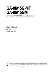
<strong>6OMM7E</strong> <strong>6OMM7E</strong> PS/2JP3JP1JP2JP4LED1USBLANPGA 370CPUJ1JP6J2JP7VGA COM ALPTJP34JP5<strong>6OMM7E</strong>FW82815COM BGame & AudioJP10JP11JP26IDE2ATX PowerIDE1FloppyJP31IT8712AC’97AGPDFP/TVDIMM1DIMM2DIMM3J10JP12JP32PCI1BZ1J7J12J13ICH2JP14JP13PCI2JP30J6JP24FWHJ5PCI3BAT1J11JP20 JP21JP23CNRJP22JP15JP18J14JP335
<strong>6OMM7E</strong> $ CPU / CPU P.8 P.9 P.9COM A / COM B / / LPT P.9CN2 (USB )[Back] P.10USB & LAN (USB&LAN )[LAN ] P.10PS/2 PS/2 P.11J1 (CPU) P.11J2 () P.12J14 () P.12ATX P.13JP13 (IR/CIR) [/] P.13Floppy ( ) P.14 IDE 1 / IDE 2 P.14J13 (Ring Power On) () P.15J12 (Wake On LAN) () P.15J7 (TEL) () P.16J6 (AUX_IN ) P.16J5 () P.17JP7 (STR& LED1: DIMM LED) [ ] P.17JP32 (USB )(Front) P.18J10 ( SMBUS ) P.18CN8 (/) [DFP/TV Out ] P.19 P.20J11 (2x11 Pins ) P.20JP18 ( CMOS ) P.21JP30 (PB ) P.21JP15 () P.22JP22 () P.22JP4 (STR) [ ] P.23JP3 (PS/2) P.23JP1 ( USB) P.24JP20 (BIOS ) P.246
<strong>6OMM7E</strong> JP21 (Top Block Lock ) P.25JP5 (CPU ) P.25JP6 (DIMM ) P.26JP12 () [ ] P.26JP14 () P.27JP23 (PCI/AGP 3VAUX) P.27JP24 (CNR ) [ ] P.28JP2 (Cyrix CPU ) [ ] P.28JP34 (Onboard LAN ) [ ] P.29JP31 (Front USB Keyboard Wake Up) P.297
CPU CPUJP10/JP11JP26( 1), 66MHz, 100MHz 133MHz Auto. CPU BIOSM CPUJP10/JP11/JP26: CPU ( )111JP10JP11JP26CPU SDRAM JP10 JP11 JP26Auto Auto 1-2 1-2 1-266 100 2-3 2-3 1-2100 100 2-3 Open 1-2133 133 Open 2-3 1-2133 100 Open Open 2-3:CPU SDRAM66 100100 100133 1331Ö CPU 133 MHz, BIOS SDRAMSPD, Memory .M JP10,JP11JP26 , BIOS . 3, 66MHz, 100MHz, 133MHz Auto.M CPU ,,, , ;CPU,, ,.8
<strong>6OMM7E</strong> GamePortLine Out MIC InLine InCOM A / COM B / / LPTLPT PORTCOM A21COM B109VGA9
CN2: USB (Back)1 2 3 45 6 7 8 1 USB V02 USB D0-3 USB D0+4 5 USB V16 USB D1-7 USB D1+8 USB & LAN : USBLAN (LAN)12142 35 6 7 81 – Green LED(LAN Link LED)2 – Yellow LED(LAN Active LED) 1 USB V02 USB D0-3 USB D0+4 5 USB V16 USB D1-7 USB D1+8 10
<strong>6OMM7E</strong> PS/2 PS/2PS/2 PS/2 1 6 52 3 3 4 VCC(+5V)2 1 5 PS/2 6 4J1: CPU 1 1 2 +12V3 11
J2: 1 1 2 +12V3 J14: 1 1 2 +12V3 12
<strong>6OMM7E</strong> ATX 10 201 11 3,5,7,13,15-171,2,11 3.3V4,6,19,20 VCC10 +12V12 -12V18 -5V8 9 5V SB stand by+5V14 PS-ON(Soft On/Off)JP13: IR/CIR(/)15610 1 2 3 IRRX4 5 IRTX6 7 CIRRX8 9 10 13
Floppy: IDE 1 / IDE 2IDE 2 IDE 114
<strong>6OMM7E</strong> J13: Ring Power On ()11 2 J12: Wake On LAN ()11 +5V SB2 3 15
J7: TEL: 1 1 Signal-In2 3 4 Signal-OutJ6: AUX_IN 1 1 AUX-L2 3 4 AUX-R16
<strong>6OMM7E</strong> J5: CD Audio Line In ()1 1 CD-L2 3 4 CD-RJP7: STR LED1 : DIMM ( )DIMM +1STR 17
JP32: USB (Front)1 29 10 1,10 +5V2,9 3,5 USBP0+/-4,7 6,8 USBP+/-J10 : SMBUS1 1 SMB CLK2 3 4 SMB DATA5 +5V18
<strong>6OMM7E</strong> CN8: /(DFP/TV Out)íDigital Flat Panel/TV-Out (GA-DFP-x).12272819
J11: For 2x11 Pins GN1HD1GD PW P+ P− P−111S P KREGN : : (Green Switch) : GD : 1: LED (+)(Green LED) 2: LED (−)HD : 1: LED (+)(IDE Hard Disk Active LED) 2: LED (−)SPK : (Speaker Connector) 1: VCC(+) 2- 3: 4: (−)RE : : (Reset Switch) : P+P−P− : 1: LED (+)(Power LED) 2: LED (−) 3: LED (−)PW : /(Soft Power Connector) : : 20
<strong>6OMM7E</strong> 21
JP30: PB1 215 16. 1 HD LED+2 GD+3 HD LED-4 PWR LED+5,8, 12,136 Power Switch7 Reset9,16 VCC10 11 IRRX14 15 IRTXJP18: CMOS1 1-2 CMOS2-3 22
<strong>6OMM7E</strong> JP15: Safe mode / Recovery / Normal 1 1-2 ( )2-3 1-2-3 BIOS JP22: 11 2 23
JP4: STR ( )1 STR STRJP3: PS/2 1 1-2 PS/2 2-3 24
<strong>6OMM7E</strong> JP1: USB(USB Conn. à USB1)1 1-2 USB /2-3 ( )USB 1( "USB KB/Mouse Wake from S3" , BIOS "USB KB/Mouse Wake from S3", Jumper "JP1" ).*(, . BIOS ,”POWER MANAGEMENTSETUP", "USB KB/Mouse Wake from S3:Enabled". "ESC" "SAVE & EXITSETUP" )JP20: BIOS1 ( )M BIOS , JumperJP20 ” ”, BIOS .25
JP21: Top Block Lock 1 Top Block LockTop Block Unlock ( )JP5: CPU (Magic Booster)(JP5 ” ”,CPU Voltage 10%)1 Turbo[ 10%] ( )26
<strong>6OMM7E</strong> JP6: DIMM 1 DIMM DIMM ( )JP12: ( )1 ( )27
JP14: 1 ( )JP23: PCI/AGP 3VAUX ( )1 PCI/AGP 3VAUX PCI/AGP 3VAUX( )M 3VAUX PCI/AGP 3V Standby , Suspend , PME 28
<strong>6OMM7E</strong> JP24: CNR ( )1 1-2 CNR Secondary ( )CNR Primary2-3 AC’97 Disabled( Onboard CODEC)JP2: Cyrix CPU ( )1 29
JP34: On Board LAN ( )1 1-2 Onboard LAN( )2-3 Onboard LANJP31: Front USB Keyboard Wake Up 1 1-2 Front USBKeyboard Wake Up( )2-3 Normal30
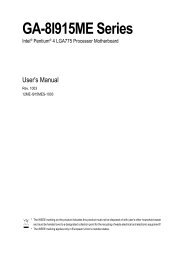
<strong>6OMM7E</strong> • CPU Intel ® Celeron ® 700MHz , Intel ® Coppermine 933MHz ,850MHz• (256 x 1) MB SDRAM (HYUNDAI HUM71V733201)• CPU 256 KB(Pentium ® !!!)CPU 128 KB(Celeron TM )• • IDE (Quantum KA13600AT)• Windows NT 4.0 (SP6a)• 1024 x 768 x 16M x 75Hz Intel Ultra ATA Storage Driver V6.0, Build 6.00.011ProcessorIntelCoppermine933(133x7)IntelCoppermine850(100x8.5)IntelCeleron700(66x10.5)Winbench99CPU mark 99 80.8 71.2 47FPU Winmark 99 4980 4520 3730Business Disk Winmark 99 5670 5560 5450Hi-End Disk Winmark 99 12200 12700 13100Business Graphics Winmark 99 132 119 107Hi-End Graphics Winmark 99 627 565 424Winstone99Business Winstone99 40.4 38.1 31Hi-End Winstone99 51 47.3 36.2M 5031
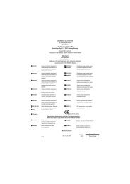
<strong>6OMM7E</strong> AGP2X/4XDisplaySocket 37066/100/133 MHzHost Bus 66/100/133MHz66/100/133 MHzDFP/TVDisplay CacheSDRAMSDRAMATA66 IDE ChannelsIntelFW82815ICH82801BAHubInterface14.318/33/48/66 MHzPCI Bus 33MHzAC’97 Link3.3V SDRAM100 MHz3 PCIICS9250-254 USB PortsFWHCOM PortsLPT PortsIT8712Game PortAC’97CNRPS/2IR Floppy31
Suspend To RAM Suspend To RAM ( )A.1 STR STR Windows 98 ACPISTR ,STR(S3), , STR,STR,A.2 STR STR 1: STR , Windows 98 ACPI : Windows 98A. Windows 98, , B. Window “D:\setup /p j”, enter 12/01/99 BIOS , Windows98 ACPI Compatible BIOS. "D:\Setup", ACPI mode.C. ,,(D:)32
<strong>6OMM7E</strong> 2: STR ,JP4 ,:1 STR STR 3:, BIOS ,”POWER MANAGEMENT SETUP”, ”ACPI Suspend Type: S3(Suspend toRAM)””ESC” ”SAVE & EXIT SETUP” !!STR33
Suspend To RAMA.3 STR ?:1. ” Windows” ” ” A. Windows98” ” ” ”B. ” ””34
<strong>6OMM7E</strong> 2. STR :A. ”” ” B. ”35
Suspend To RAMC. ” ” ”. 4 :.STR, ””A.4 STR ?7 ” ” :1. ”2. ”PS/2 ” 3. ”PS/2 ”4. ”5. ”6. ”7. ”USB ”36
<strong>6OMM7E</strong> 37
A.5 : Suspend To RAM1.STR ,:A. ATX ATX 2.01 ( 720 5VStand-By )B. SDRAM PC-100 .2. JP7 STR.STR, STR.DIMM +1STR 38
<strong>6OMM7E</strong>3(DIMM) . BIOS.DIMM, , ,.:DIMM 168-pin SDRAM DIMM ModulesDIMM1 Supports 16 / 32 / 64 / 128 / 256 / 512MB X 1 pcsDIMM2 Supports 16 / 32 / 64 / 128 / 256 / 512MB X 1 pcsDIMM3 Supports 16 / 32 / 64 / 128 / 256 / 512MB X 1 pcs38
<strong>6OMM7E</strong> $ BIOS P.41 CMOS P.44 BIOS P.47 P.50 P.53 P.59PCI P.63 P.65 / P.67 Fail-Safe P.68 Optimized P.69(Supervisor)/ (User) P.70 SETUP P.71 SETUP P.7239
BIOS BIOS Award BIOS CMOS SETUP.CMOS SETUPCMOS SRAMCMOS SRAMBIOS POSTPower On Self Test DelAward BIOSCMOS SETUPPOSTDelCMOS SETUPCtrl Alt DelResetPOSTDel CMOS SETUPá â ßà Esc Page UpPage DownSETUPF1 F2 F3 F4 F5 ()F6 Fail-Safe ()F7 Optimized ()F8 F9 F10 CMOS SETUP SETUPSETUP40
<strong>6OMM7E</strong> F1BIOS CMOS SETUP CMOS SETUP,,EnterCMOS Setup Utility -Copyright( C ) 1984-2000 Award Software4Standard CMOS Features4Advanced BIOS Features4Advanced Chipset Features4Integrated Peripherals4Power Management Setup4PnP/PCI Configurations4PC Health StatusESC:QuitF10:Save & Exit Setup4Frequency/Voltage ControlLoad Fail-Safe DefaultsLoad Optimized DefaultsSet Supervisor PasswordSet User PasswordSave & Exit SetupExit Without Saving↑↓→ ← : Select ItemTime, Date, Hard Disk Type…2: • Standard CMOS Features ( CMOS )• Advanced BIOS features ( BIOS ) BIOS....41
BIOS • Advanced Chipset features ()DRAM Timing ISA Clock ....• Integrated peripherals ()COM Port IRQ LPTPort SPPEPPECP IDE PIO Mode…..• Power management setup() CPU GREEN• PnP/PCI configuration(PCI ) ISAPnPPCI• PC Health Status (),• Frequency/Voltage Control ( / ) CPU• Load Fail-Safe defaults( Fail-Safe )BIOSCMOS• Load Optimized defaults( Optimized )OptimizedCMOS• Set Supervisor password ()SETUP CMOS• Set User password ()PC BIOS42
<strong>6OMM7E</strong> • Save & exit setup ()SETUPBIOSF10• Exit without save ( SETUP )43
CMOSBIOS STANDARD CMOS SETUPIDECMOS Setup Utility -Copyright( C ) 1984-2000 Award SoftwareStandard CMOS FeaturesDate (mm:dd:yy) Mon , Feb 21 2000 Item HelpTime (hh:mm:ss) 2 : 31 : 24Menu Level 44IDE Primary MasterPress Enter None4IDE Primary Slave Press Enter None Change the4IDE Secondary Master Press Enter None Day, month,4IDE Secondary Slave Press Enter None Year andcenturyDrive A1.44M, 3.5 in.Drive BNoneFloppy 3 Mode Support DisabledVideoHalt OnBase MemoryExtended MemoryTotal MemoryEGA / VGAAll, But Keyboard640K63488K64512K↑↓→ ←:Move Enter:Select +/-/PU/PD:Value F10:Save ESC:Exit F1:General HelpF5:Previous Values F6:Fail-Safe Defaults F7:Optimized Defaults3: CMOS• Date(mm:dd:yy) ( )// .(mm) 112.(dd) 128/29/30/31.(yy) 19942079.44
<strong>6OMM7E</strong> • Time(hh:mm:ss) ( )2413 : 00 : 00RTC• IDE Primary Master (Slave) / IDE Secondary Master (Slave) (/)IDE 1IDE2 CMOS 1 User TYPECYLSHEADSSECTORSMODE 2 AUTO TYPEMODE AUTO BIOSPOST IDECYLS.HEADSPRECOMPLANDZONESECTORSNumber of cylinders().number of heads().write precomp.Landing zone.number of sectors().”NONE” • Drive A / Drive B (A:/ B: )None .360K, 5.25 in. 5.25360KB .1.2M, 5.25 in. 5.251.2MB .720K, 3.5 in. 3720KB .1.44M, 3.5 in. 31.44MB .2.88M, 3.5 in. 32.88MB .• Floppy 3 Mode Support (3 Mode )DisabledDrive ADrive BBoth3 Mode .A: 3 Mode .B: 3 Mode .A:B:3 Mode .45
BIOS • Video()EGA/VGACGA 40CGA 80MONOEGA, VGA, SVGA, or PGA.Color Graphics Adapter40.Color Graphics Adapter80..• Halt on()POSTNO ErrorsAll ErrorsAll, But KeyboardAll, But DisketteAll, But Disk/Key• Memory()BIOSPOST(Power On Self Test) STANDARD CMOS SETUPBase MemoryPC640KB MS-DOSExtended MemoryBaseOther MemoryModule46
<strong>6OMM7E</strong> BIOS CMOS Setup Utility -Copyright( C ) 1984-2000 Award SoftwareAdvanced BIOS FeaturesVirus Warning Disabled Item HelpBIOS Flash ProtectionDisabledøProcessor Number Feature Enabled Menu Level 4First Boot Device Floppy Allows you toSecond Boot Device HDD-0 choose the VIRUSThird Boot Device LS120 Warning featureBoot Up Floppy Seek Enabled For IDE Hard diskBoot Up NumLock Status On Boot sectorSecurity Option Setup Protection. If thisHDD S.M.A.R.T. Capability Disabled Function is enableReport No FDD For WIN 95 No And someoneAttempt to writeData into this area, BIOS will showA warningMessage onScreen and alarmbeep↑↓→ ←:Move Enter:Select +/-/PU/PD:Value F10:Save ESC:Exit F1:General HelpF5:Previous Values F6:Fail-Safe Defaults F7:Optimized Defaults4: BIOS ø Pentium ® !!! , .• Virus Warning( )EnabledDisabled..( )• BIOS Flash Protection (BIOS )EnabledDisabled BIOS .. ( )47
BIOS • Processor Number Feature Pentium ® !!! EnabledDisabledPentium ® !!! . ( ).• First / Second / Third Boot device ( //)FloppyLS120ZIP100HDD-0~3SCSICDROMDisableLAN.LS120.ZIP100..SCSI....• Boot Up Floppy Seek PC POSTFLOPPY SEEKEnabled FloppySeek .( )Disabled FloppySeek .• Boot Up NumLock StatusOnOff.( ).• Security OptionSystemSetupCMOS SETUP.CMOS SETUP.( )M SETUP Enter48
<strong>6OMM7E</strong> • HDD S.M.A.R.T. Capability ( )EnabledDisabled S.M.A.R.T. . S.M.A.R.T. .( )• Report No FDD For WIN 95 ( IRQ6FDD)NoYes IRQ6FDD.( )FDD IRQ6.49
BIOS CMOS Setup Utility -Copyright( C ) 1984-2000 Award SoftwareAdvanced Chipset FeaturesTop Performance Disabled Item HelpSDRAM Timing ControlAutoø SDRAM CAS Latency Time 3 Menu Level 4ø SDRAM Cycle Time Tras/Trc 6/8ø SDRAM RAS-to-CAS Delay 3ø SDRAM RAS Precharge Time 3Delayed TransactionEnabledOn-Chip Video Window Size 64MBAGP Graphics Aperture Size 64MBDisplay Cache Frequency133MHzöSystem Memory Frequency AutoÜOnboard Display Cache SettingÜ♣Initial Display Cache♣Display Cache TimingEnabledAuto↑↓→ ←:Move Enter:Select +/-/PU/PD:Value F10:Save ESC:Exit F1:General HelpF5:Previous Values F6:Fail-Safe Defaults F7:Optimized Defaults5: ø”SDRAM Timing Control” Manual, 4.ö133MHz,.♣GA-AIMM card,2 .• Top Performance ( )“Top Performance” “Enabled”.DisabledEnabled• SDRAM Timing Control. ( ).AutoManual SDRAM Timing Control . ( ) SDRAM Timing Control .• SDRAM CAS Latency Time(SDRAM CAS )2 SDRAM CAS Latency 2.3 SDRAM CAS Latency 3. ( )50
<strong>6OMM7E</strong> • SDRAM Cycle Time Tras/Trc6/8 DRAM Tras/Trc Cycle time 6/8 SCLKs. ( )5/7 DRAM Tras/Trc Cycle time 5/7 SCLKs.• SDRAM RAS-to-CAS Delay3 67 / 83 MHz SDRAM DIMM.( )2 100 MHz SDRAM DIMM.• SDRAM RAS Precharge Time3 67 / 83 MHz SDRAM DIMM.( )2 100 MHz SDRAM DIMM.• Delayed Transaction()DisabledEnabled• On-Chip Video Window Size32MB64MB• AGP Graphics Aperture Size .ISA .( ) Graphics Aperture Size 32MB. Graphics Aperture Size 64MB. ( )32 MB AGP Graphics Aperture Size 32MB.64 MB AGP Graphics Aperture Size 64MB. ( )• Display Cache Frequency100MHz133MHz Display Cache Frequency 100MHz. Display Cache Frequency 133MHz. ( )• System Memory FrequencyAuto100MHz133MHzSystem Memory Frequency. ( ) System Memory Frequency 100MHz. System Memory Frequency 133MHz.• Initialize Display Cache51
DisabledEnabled Initialize Display Cache. Initialize Display Cache. ( )BIOS 52
<strong>6OMM7E</strong> • Display Cache TimingAutoFastNormal Display Cache Timing Auto. ( ) Display Cache Timing Fast. Display Cache Timing Normal.53
BIOS CMOS Setup Utility -Copyright( C ) 1984-2000 Award SoftwareIntegrated PeripheralsOn-Chip Primary PCI IDE Enabled Item HelpOn-Chip Secondary PCI IDE EnabledIDE Primary Master PIO Auto Menu Level 4IDE Primary Slave PIOAutoIDE Secondary Master PIOAutoIDE Secondary Slave PIOAutoIDE Primary Master UDMAAutoIDE Primary Slave UDMAAutoIDE Secondary Master UDMA AutoIDE Secondary Slave UDMA AutoUSB ControllerEnabledUSB Keyboard SupportDisabledUSB Mouse SupportDisabledInit Display FirstPCI SlotAC97 AudioAutoAC97 ModemAutoIDE HDD Block ModeEnabledPower On by KeyboardDisabledX KB Power ON PasswordEnterPower On by MouseDisabledOnboard FDC ControllerEnabledOnboard Serial Port 13F8/IRQ4Onboard Serial Port 22F8/IRQ3UART Mode SelectNormalUR2 Duplex ModeHalfOnboard Parallel Port378/IRQ7Parallel Port ModeSPPAC Back FunctionSoft-OffGame Port Address 201Midi Port Address 330Midi Port IRQ 10↑↓→ ←:Move Enter:Select +/-/PU/PD:Value F10:Save ESC:Exit F1:General HelpF5:Previous Values F6:Fail-Safe Defaults F7:Optimized Defaults6: 54
<strong>6OMM7E</strong> • On-Chip Primary IDE (channelPCI IDE )EnabledDisabledchannelIDE .( ) .• On-Chip Secondary IDE (channelIDE )Secondary IDEEnabledDisabledchannelPCI IDE .( ) .• IDE Primary Master PIO (for onboard IDE 1st channel). IDEPrimary MasterPIO0/1/2/3/4IDE BIOSAutoBIOSAutoMode0~4BIOS IDE.( )04.• IDE Primary Slave PIO (IDE SlavePIO Mode).AutoMode0~4BIOS IDE.( )04.• IDE Secondary Master PIO (IDE MasterPIO Mode).AutoMode0~4BIOS IDE.( )04.• IDE Secondary Slave PIO (IDE SlavePIO Mode).AutoMode0~4BIOSIDE HDD .( ) IDE .• IDE Primary Master UDMA IDEPrimary MasterUltra DMAAutoBIOSUltra DMAAutoDisabledBIOS IDEUltra DMA.( ) Ultra DMA.55
• IDE Primary Slave UDMA (Primary SlaveUltra DMA)BIOS AutoDisabledBIOS IDEUltra DMA.( ) Ultra DMA .• IDE Secondary Master UDMA (Secondary MasterUltra DMA)AutoDisabledBIOS IDEUltra DMA.( ) Ultra DMA .• IDE Secondary Slave UDMA (Secondary SlaveUltra DMA)AutoDisabledBIOS IDEUltra DMA.( ) Ultra DMA .• USB ControllerEnabledDisabled USB Controller. ( ) USB Controller.• USB Keyboard Support ( USB )EnabledDisabled USB. (USB DeviceUSB,Enabled) USB.( )• USB Mouse Support ( USB )EnabledDisabled USB. (USB DeviceUSB,Enabled) USB.( )• Init Display First ()Onboard/AGPPCI SlotAGP . PCI .( )• AC’97 AudioAutoDisabled AC’97 Audio .( ) AC’97 Audio.56
<strong>6OMM7E</strong> • AC’97 ModemAutoDisabled AC’97 Modem . ( ) AC’97 Modem• IDE HDD Block ModeIDEIDE(120MB)EnabledDisabledIDE HDD Block Mode.( ) .• POWER ON by Keyboard ()PasswordDisabledKeyboard 98 1-5.. ( )Windows 98 ”Power” Key.• KB Power ON Password ()Enter 1-5• POWER ON by Mouse ()Mouse ClickDisabled PS/2.. ( )• Onboard FDC ControllerEnabledDisabled.( ).• Onboard Serial Port 1Auto3F8/IRQ42F8/IRQ33E8/IRQ42E8/IRQ3DisabledBIOS .1COM 1 3F8 . ( )1COM 2 2F8 .1COM 3 3E8 .1COM 4 2E8 .1.57
• Onboard Serial Port 2 2BIOS Auto3F8/IRQ42F8/IRQ33E8/IRQ42E8/IRQ3DisabledBIOS .2COM 1 3F8 .2COM 2 2F8 . ( )2COM 3 3E8 .2COM 4 2E8 .2.• UART Mode Select (I/O IR )ASKIRIrDASCRNormal I/OASKIR . I/OIrDA . I/OSCR . I/O. ( )• UR2 Duplex ModeHalfFull IR . ( ) IR .• Onboard Parallel port()378/IRQ7278/IRQ53BC/IRQ7Disabled378 / IRQ7.( )278 / IRQ5.3BC / IRQ7..• Parallel Port ModeSPPEPPECPECP+EPP.( ) EPPEnhanced Parallel Port. ECPExtended Capabilities Port. EPPECP .• AC Back Function ,MemoryFull-OnSoft-Off.. Soft PWR button. ( )58
<strong>6OMM7E</strong> • Game Port AddressDisabled .201 Game port 201. ( )209 Game port 209.• Midi Port AddressDisabled Midi Port .300 Midi Port 300.330 Midi Port 330. ( )• Midi Port IRQ5 5 Midi Port IRQ.10 10 Midi Port IRQ. ( )59
BIOS CMOS Setup Utility -Copyright( C ) 1984-2000 Award SoftwarePower Management SetupVideo Off Method DPMS Item HelpSuspend TypeStop GrantMODEM Use IRQ 4 Menu Level 4Suspend ModeDisabledHDD Power DownDisabledSoft-Off by PWR-BTTNInstant-offPower LED in SuspendBlinkingWake-Up by PCI cardEnabledModemRingOn/WakeOnLan EnabledFAN Off In SuspendEnabledCPU Thermal-Throttling 50%Resume by AlarmDisabled* Date(of Month) Alarm 0* Time(hh:mm:ss) Alarm 0 0 0** Reload Global Timer Events **Primary IDE 0Primary IDE 1Secondary IDE 0Secondary IDE 1FDD,COM,LPT PortPCI PIRQ[A-D]#DisabledDisabledDisabledDisabledDisabledDisabled↑↓→ ←:Move Enter:Select +/-/PU/PD:Value F10:Save ESC:Exit F1:General HelpF5:Previous Values F6:Fail-Safe Defaults F7:Optimized Defaults7: • Video Off MethodBIOSV/H SYNC +BlankBlank ScreenDPMSBIOSMonitor.BIOS.BIOS DPMS.( )60
<strong>6OMM7E</strong> • Suspend TypeStop GrantPwrOn Suspend Suspend type stop grant. ( ) Suspend type Power on suspend.• MODEM Use IRQNA MODEM IRQ .3 MODEM Use IRQ 3.4 MODEM Use IRQ 4. ( )5 MODEM Use IRQ 5.7 MODEM Use IRQ 7.9 MODEM Use IRQ 9.10 MODEM Use IRQ 10.11 MODEM Use IRQ 11.• Suspend Mode PCSuspendCPU0MhzCPU FANVideo offDisabled1Min - 1Hour Suspend Mode. ( )1 1 .• HDD Power DownDisable . ( )1-15 mins. 115 .• Soft-off by PWR-BTTNInstant-offDelay 4Sec. Soft-off. ( ) Soft-off 4.• Power LED in SuspendBlinkingOnOff/Dual. ( )..61
62BIOS
<strong>6OMM7E</strong> • Wake-Up by PCI cardDisabledEnabled. PCI . ( )• ModemRingOn/WakeOnLan (/)DisabledEnabled/./. ( )• FAN Off In Suspend (CPU)DisabledEnabled.CPU. ( )• CPU Thermal-Throttling87.5% CPU , CPU87.5% CPU .75.0% CPU , CPU75.0% CPU .62.5% CPU , CPU62.5% CPU .50.0% CPU , CPU50.0% CPU . ( )37.5% CPU , CPU37.5% CPU .25.0% CPU , CPU25.0% CPU .12.5% CPU , CPU12.5% CPU .• Resume by Alarm( ) ” Resume by Alarm””Enabled”.DisabledEnabled. ( ).:Date ( of Month) Alarm : Everyday, 1~31Time ( hh: mm: ss) Alarm : (0~23) : (0~59) : (0~59)63
BIOS • Primary IDE 0/1( IDE ) IDE 0/1PC IDEDisabledEnabled . ( )PC.• Secondary IDE 0/1( IDE )DisabledEnabled . ( ) PC.• FDD,COM,LPT Port, , DisabledEnabled . ( )PC.• PCI PIRQ[A-D] #EnabledDisabled PCI PIRQ[A-D] , .. ( )64
<strong>6OMM7E</strong> PCICMOS Setup Utility -Copyright( C ) 1984-2000 Award SoftwarePnP/PCI ConfigurationsReset Configuration Data Disabled Item HelpResources Controlled By Auto (ESCD) Menu Level 4X IRQ ResourcesPress EnterWhen resources arePCI/VGA Palette Snoop Disabled controlled manually,assign each systeminterrupt a type,depending on the typeof device using theinterrupt↑↓→ ←Move Enter:Select +/-/PU/PD:Value F10:Save ESC:Exit F1:General HelpF5:Previous Values F6:Fail-Safe Defaults F7:Optimized Defaults8: PCI• Reset Configuration Data BIOS PnPDisabledESCDDMIBoth Reset Configuration Data. ( ) ESCD.. ESCD.• Resources Controlled byManualAuto (ESCD) CMOS SETUPISA .BIOSPnP( ).65
• IRQ (3,4,5,7,9,10,11,12,14,15)BIOS IRQPCCOM 1(IRQ 4)COM 2(IRQ 3)LPT(IRQ 7)IDE(IRQ 14,15) IRQ5/9/10/11 BIOSPnPVGA....ReservedPCI Device. PCI PnP.• PCI/VGA Palette Snoop MPEGEnabledEnabledDisabled.. ( )66
<strong>6OMM7E</strong> CMOS Setup Utility -Copyright( C ) 1984-2000 Award SoftwarePC Health StatusReset Case Open Status Disabled Item HelpCase OpenedNoVCORE 1.600 V Menu Level 4VGTL1.424 VVCC33.264 V+ 5V 5.053 V+12V 12.160V- 12V -12.280 V5VSB(V)5.026 VVBAT(V)3.168 VCurrent CPU Temperature 31°CCPU FAN Speed5443 RPMPower FAN Speed0 RPMSystem FAN speed0 RPMCPU Temperature Select80°C/176°FShutdown TemperatureDisabledCPU FAN Fail AlarmDisabledPower FAN Fail AlarmDisabledSystem FAN Fail AlarmDisabled↑↓→ ←Move Enter:Select +/-/PU/PD:Value F10:Save ESC:Exit F1:General HelpF5:Previous Values F6:Fail-Safe Defaults F7:Optimized Defaults• Reset Case Open Status Case Opened • Case Opened9: , “ Case Opened” “No”., “ Case Opened” “YES”.“Case Opened” ,”Reset Case Open Status” “Enable” .• Current Voltage (v) VCORE / VGTL / VCC3 / ±12V / +5V /5VSB /VBAT VCORE / VGTL / VCC3 / ±12V / +5V /5VSB /VBAT• Current CPU Temperature CPU 67
BIOS • CPU FAN / System FAN / Power FAN Speed (RPM)• CPU Temperature Select (°C)65°C / 149°F CPU 65°C / 149°F.70°C / 158°F CPU 70°C / 158°F.75°C / 167°F CPU 75°C / 167°F.80°C / 176°F CPU 80°C / 176°F. ( )85°C / 185°F CPU 85°C / 185°F.90°C / 194°F CPU 90°C / 194°F.95°C / 203°F CPU 95°C / 203°F.Disabled .• Shutdown Temp. (°C / °F)(ACPI )Disabled . ( )65°C / 149°F CPU 65°C / 149°F, > 65°C / 149°F .70°C / 158°F CPU 70°C / 158°F, > 70°C / 158°F .75°C / 167°F CPU 75°C / 167°F, > 75°C / 167°F .80°C / 176°F CPU 80°C / 176°F, > 80°C / 176°F .85°C / 185°F CPU 85°C / 185°F, > 85°C / 185°F .90°C / 194°F CPU 90°C / 194°F, > 90°C / 194°F .95°C / 203°F CPU 95°C / 203°F, > 95°C / 203°F .• Fan Fail Alarm (CPU/ Power/System )EnabledDisabled CPU / Power / System . CPU / Power / System . ( )68
<strong>6OMM7E</strong> /CMOS Setup Utility -Copyright( C ) 1984-2000 Award SoftwareFrequency/Voltage ControlAuto Detect DIMM/PCI Clk Enabled Item HelpCPU Clock RatioX3Menu Level 4↑↓→ ←Move Enter:Select +/-/PU/PD:Value F10:Save ESC:Exit F1:General HelpF5:Previous Values F6:Fail-Safe Defaults F7:Optimized Defaults10: /• Auto Detect DIMM/PCI Clk ()DisabledEnabled.. ( )• CPU Clock Ratio(CPU )CPU ,.X3/X3.5X/X4/X4.5/X5/X5.5/X6/X6.5/X7/X7.5/X869
BIOS Fail-Safe CMOS Setup Utility -Copyright( C ) 1984-2000 Award Software4Standard CMOS Features4Advanced BIOS Features4Advanced Chipset Features4Integrated Peripherals4Power Management Setup4Frequency/Voltage ControlLoad Fail - Safe DefaultsLoad Optimized DefaultsSet Supervisor PasswordSet User Password4PnP/PCI Configurations Load Fail-Safe Defaults Save (Y/N)? & Exit N Setup4PC Health StatusESC:QuitF10:Save & Exit SetupExit Without Saving↑↓→ ← : Select ItemLoad Fail-Safe Defaults11: Fail-Safe Y EnterBIOS MFail-Safe DefaultsFail-Safe Defaults70
<strong>6OMM7E</strong> Optimized CMOS Setup Utility -Copyright( C ) 1984-2000 Award Software4Standard CMOS Features4Advanced BIOS Features4Advanced Chipset Features4Integrated Peripherals4Power Management Setup4Frequency/Voltage ControlLoad Fail-Safe DefaultsLoad Optimized DefaultsSet Supervisor PasswordSet User Password4PnP/PCI Configurations Load Optimized Defaults Save &(Y/N)? Exit Setup N4PC Health StatusESC:QuitF10:Save & Exit SetupExit Without Saving↑↓→ ← : Select ItemLoad Optimized Defaults12: Optimized Y EnterMLoad Optimized DefaultsCMOS71
(Supervisor)/ (User)BIOS EnterCMOS Setup Utility -Copyright( C ) 1984-2000 Award Software4Standard CMOS Features4Advanced BIOS Features4Advanced Chipset Features4Integrated Peripherals4Power Management SetupEnter Password:4PnP/PCI Configurations4Frequency/Voltage ControlLoad Fail-Safe DefaultsLoad Optimized DefaultsSet Supervisor PasswordSet User PasswordSave & Exit Setup4PC Health StatusESC:QuitF10:Save & Exit SetupExit Without Saving↑↓→ ← : Select ItemChange / Set / Disable Password13: (Supervisor)/ (User)8EnterBIOSEnter BIOSPASSWORD DISABLEDv SUPERVISOR SupervisorAdvanced BIOS Features Securityoption SETUPCMOS SETUP Supervisorv USER UserAdvanced BIOS Features Security option SYSTEMUserSupervisorCMOS SETUPUSER Password BIOSSupervisor CMOS SETUP72
<strong>6OMM7E</strong> SETUPCMOS Setup Utility -Copyright( C ) 1984-2000 Award Software4Standard CMOS Features4Advanced BIOS Features4Advanced Chipset Features4Integrated Peripherals4Power Management Setup4Frequency/Voltage ControlLoad Fail-Safe DefaultsLoad Optimized DefaultsSet Supervisor PasswordSet User Password4PnP/PCI Configurations SAVE to CMOS and Save EXIT & (Y/N)? Exit Setup Y4PC Health StatusESC:QuitF10:Save & Exit SetupExit Without Saving↑↓→ ← : Select ItemSave Data to CMOS14: SETUP Y EnterRTC CMOS Setup Utility NEsc73
BIOS SETUPCMOS Setup Utility -Copyright( C ) 1984-2000 Award Software4Standard CMOS Features4Advanced BIOS Features4Advanced Chipset Features4Integrated Peripherals4Power Management Setup4Frequency/Voltage ControlLoad Fail-Safe DefaultsLoad Optimized DefaultsSet Supervisor PasswordSet User Password4PnP/PCI Configurations Quit Without Saving Save (Y/N)? & Exit N Setup4PC Health StatusESC:QuitF10:Save & Exit SetupExit Without Saving↑↓→ ← : Select ItemAbandon all Datas15: SETUP Y Enter Setup Utility NEsc74
<strong>6OMM7E</strong> A: Intel 815 A. Windows 9x INF Update Utility(IUCD),.,.(, ” ”ICON).1. “Windows 9x INFUpdate Utility” .(1)2.”Next”.(2)3. ”Yes”.4.”Next”.(3) (4)5. “Finish” .(5) (6)73
B: Intel 815 Chipsets VGA Graphics Driver(IUCD),.,.(, ” ”ICON).1. “Intel 815 Chipset VGAGraphics Driver” .(1)2. ”Next”.(2)3.4.(3) (4)5. “Finish” .(5) (6)74
<strong>6OMM7E</strong> C: SigmaTel Sound Driver(IUCD),.,.(, ” ”ICON). “Audio” 1. “SigmaTel Sound Driver” .(1)2. “Next “.(2)3. “Yes4. “Next(3) (4)5. “Finish” .(5)75
D : BIOS BIOS :üüüüBIOS (AMIAWARD).”AWDFlash.exeAMIFlash.exe”(D:\>Utility \BIOSFlash)BIOS.[ i.e: C:\>Utility \ (C:/Utility )]Win95/98MS-DOS(Command prompt only) , BIOS. ”AWDFlash.exeAMIFlash.exe” BIOS, :C:\Utility \”AWDFlashAMIFlash ü, .MNote: website (WWW.gigabyte.com.tw) BIOSBIOS.76
<strong>6OMM7E</strong> E: CNR CNR Card, . ( A)PCI SlotA: CNR Card ( )77
F: GA-AIMM Card ( ) :1.( ). 2...(1) (2) :3. AGP , . 4. ( ).( )(3) (4)78