- Page 1 and 2: MicroLogix 1400ProgrammableControll
- Page 3 and 4: Summary of ChangesTo help you locat
- Page 5 and 6: Table of ContentsSummary of Changes
- Page 7 and 8: Table of Contents 7EQU - EqualNEQ -
- Page 9 and 10: Table of Contents 9Chapter 18Input
- Page 11 and 12: Table of Contents 11DLG - Data Log
- Page 13 and 14: PrefaceRead this preface to familia
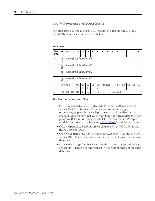
- Page 15 and 16: Chapter 1I/O ConfigurationThis sect
- Page 17 and 18: I/O Configuration 17MicroLogix 1400
- Page 19 and 20: I/O Configuration 19WordBit Positio
- Page 21 and 22: I/O Configuration 21Scaled-for-PID
- Page 23 and 24: I/O Configuration 231762-OF4 Input
- Page 28 and 29: 28 I/O ConfigurationAddressing exam
- Page 30 and 31: 30 I/O ConfigurationInput filtering
- Page 32 and 33: 32 I/O ConfigurationConverting Anal
- Page 34 and 35: 34 I/O ConfigurationRising Edge Beh
- Page 36 and 37: 36 I/O ConfigurationIMPORTANTThe in
- Page 38 and 39: 38 I/O ConfigurationNotes:Publicati
- Page 40 and 41: 40 Controller Memory and File Types
- Page 42 and 43: 42 Controller Memory and File Types
- Page 44 and 45: 44 Controller Memory and File Types
- Page 46 and 47: 46 Controller Memory and File Types
- Page 48 and 49: 48 Controller Memory and File Types
- Page 50 and 51: 50 Controller Memory and File Types
- Page 52 and 53: 52 Controller Memory and File Types
- Page 54 and 55: 54 Controller Memory and File Types
- Page 56 and 57: 56 Controller Memory and File Types
- Page 58 and 59: 56 Function FilesOverviewFunction F
- Page 60 and 61: 58 Function FilesThe real-time cloc
- Page 62 and 63: 60 Function FilesMemory ModuleInfor
- Page 64 and 65: 62 Function FilesLE - Load on Error
- Page 66 and 67: 64 Function FilesGeneral Status Blo
- Page 68 and 69: 66 Function FilesDH-485 Diagnostic
- Page 70 and 71: 68 Function FilesDF1 Half-Duplex Sl
- Page 72 and 73: 70 Function FilesDF1 Radio Modem Di
- Page 74 and 75: 72 Function FilesModbus RTU Slave D
- Page 76 and 77:
74 Function FilesPublication 1766-R
- Page 78 and 79:
76 Function FilesDNP3 Slave Diagnos
- Page 80 and 81:
78 Function FilesActive Node Table
- Page 82 and 83:
80 Function FilesEthernetCommunicat
- Page 84 and 85:
82 Function FilesGeneral Channel St
- Page 86 and 87:
84 Function FilesGeneral Channel St
- Page 88 and 89:
86 Function FilesEthernet Diagnosti
- Page 90 and 91:
88 Function FilesEthernet Diagnosti
- Page 92 and 93:
90 Function FilesNotes:Publication
- Page 94 and 95:
92 Programming Instructions Overvie
- Page 96 and 97:
94 Programming Instructions Overvie
- Page 98 and 99:
96 Programming Instructions Overvie
- Page 100 and 101:
98 Programming Instructions Overvie
- Page 102 and 103:
100 Using the High-Speed Counter an
- Page 104 and 105:
102 Using the High-Speed Counter an
- Page 106 and 107:
104 Using the High-Speed Counter an
- Page 108 and 109:
106 Using the High-Speed Counter an
- Page 110 and 111:
108 Using the High-Speed Counter an
- Page 112 and 113:
110 Using the High-Speed Counter an
- Page 114 and 115:
112 Using the High-Speed Counter an
- Page 116 and 117:
114 Using the High-Speed Counter an
- Page 118 and 119:
116 Using the High-Speed Counter an
- Page 120 and 121:
118 Using the High-Speed Counter an
- Page 122 and 123:
120 Using the High-Speed Counter an
- Page 124 and 125:
122 Using the High-Speed Counter an
- Page 126 and 127:
124 Using the High-Speed Counter an
- Page 128 and 129:
126 Using the High-Speed Counter an
- Page 130 and 131:
128 Using the High-Speed Counter an
- Page 132 and 133:
130 Using the High-Speed Counter an
- Page 134 and 135:
132 Using the High-Speed Counter an
- Page 136 and 137:
134 Using the High-Speed Counter an
- Page 138 and 139:
136 Using the High-Speed Counter an
- Page 140 and 141:
138 Using the High-Speed Counter an
- Page 142 and 143:
140 Using High-Speed Outputs• Acc
- Page 144 and 145:
142 Using High-Speed Outputsstructu
- Page 146 and 147:
144 Using High-Speed OutputsTIPIf t
- Page 148 and 149:
146 Using High-Speed OutputsTIPForc
- Page 150 and 151:
148 Using High-Speed Outputs• Set
- Page 152 and 153:
150 Using High-Speed Outputsinstruc
- Page 154 and 155:
152 Using High-Speed OutputsThe cho
- Page 156 and 157:
154 Using High-Speed OutputsThe PTO
- Page 158 and 159:
156 Using High-Speed Outputs• Set
- Page 160 and 161:
158 Using High-Speed OutputsPulse T
- Page 162 and 163:
160 Using High-Speed OutputsPulse W
- Page 164 and 165:
162 Using High-Speed Outputs• Set
- Page 166 and 167:
164 Using High-Speed OutputsPWMX En
- Page 168 and 169:
166 Using High-Speed OutputsPWMX Ac
- Page 170 and 171:
168 Relay-Type (Bit) InstructionsWh
- Page 172 and 173:
170 Relay-Type (Bit) InstructionsAd
- Page 174 and 175:
172 Relay-Type (Bit) InstructionsTI
- Page 176 and 177:
174 Relay-Type (Bit) InstructionsOS
- Page 178 and 179:
176 Timer and Counter InstructionsT
- Page 180 and 181:
178 Timer and Counter InstructionsT
- Page 182 and 183:
180 Timer and Counter InstructionsT
- Page 184 and 185:
182 Timer and Counter InstructionsH
- Page 186 and 187:
184 Timer and Counter InstructionsC
- Page 188 and 189:
186 Timer and Counter InstructionsR
- Page 190 and 191:
188 Timer and Counter InstructionsN
- Page 192 and 193:
190 Compare InstructionsUsing the C
- Page 194 and 195:
192 Compare InstructionsGRT and LES
- Page 196 and 197:
194 Compare InstructionsMEQ Instruc
- Page 198 and 199:
196 Compare InstructionsNotes:Publi
- Page 200 and 201:
198 Math InstructionsAdvanced Math
- Page 202 and 203:
200 Math InstructionsUpdates to Mat
- Page 204 and 205:
202 Math InstructionsDefinitionsOve
- Page 206 and 207:
204 Math InstructionsConsiderations
- Page 208 and 209:
206 Math InstructionsNEG - NegateNE
- Page 210 and 211:
208 Math InstructionsAddressing Mod
- Page 212 and 213:
210 Math InstructionsSCP Instructio
- Page 214 and 215:
212 Math InstructionsEnter the foll
- Page 216 and 217:
214 Math InstructionsCOS - CosineAB
- Page 218 and 219:
216 Math InstructionsTAN - TangentA
- Page 220 and 221:
218 Math InstructionsThe Math Overf
- Page 222 and 223:
220 Math InstructionsACS - Arc Cosi
- Page 224 and 225:
222 Math InstructionsUse the ATN in
- Page 226 and 227:
224 Math InstructionsEnter the foll
- Page 228 and 229:
226 Math InstructionsThe RAD instru
- Page 230 and 231:
228 Math InstructionsUse the LN ins
- Page 232 and 233:
230 Math InstructionsUse the LOG in
- Page 234 and 235:
232 Math InstructionsUse the XPY in
- Page 236 and 237:
234 Math InstructionsIMPORTANTThe X
- Page 238 and 239:
236 Math InstructionsCPT Instructio
- Page 240 and 241:
238 Application Specific Instructio
- Page 242 and 243:
240 Application Specific Instructio
- Page 244 and 245:
242 Application Specific Instructio
- Page 246 and 247:
244 Conversion InstructionsDCD - De
- Page 248 and 249:
246 Conversion InstructionsMath Sta
- Page 250 and 251:
248 Conversion InstructionsTIPTo co
- Page 252 and 253:
250 Conversion InstructionsTOD - Co
- Page 254 and 255:
252 Conversion InstructionsTODTo BC
- Page 256 and 257:
254 Conversion InstructionsNotes:Pu
- Page 258 and 259:
256 Logical InstructionsAddressing
- Page 260 and 261:
258 Logical InstructionsOR - Logica
- Page 262 and 263:
260 Logical InstructionsNOT - Logic
- Page 264 and 265:
262 Move Instructions• Valid cons
- Page 266 and 267:
264 Move InstructionsMVM - Masked M
- Page 268 and 269:
266 Move InstructionsMath Status Bi
- Page 270 and 271:
268 File InstructionsCPW - Copy Wor
- Page 272 and 273:
270 File InstructionsIMPORTANTYou c
- Page 274 and 275:
272 File InstructionsTIPThe source
- Page 276 and 277:
274 File InstructionsBSL Instructio
- Page 278 and 279:
276 File InstructionsBSR Instructio
- Page 280 and 281:
278 File Instructions• Control -
- Page 282 and 283:
280 File Instructions• Destinatio
- Page 284 and 285:
282 File InstructionsLFL - Last In,
- Page 286 and 287:
284 File InstructionsLFU - Last In,
- Page 288 and 289:
286 File InstructionsSWP - SwapSWPS
- Page 290 and 291:
288 Sequencer InstructionsSQC- Sequ
- Page 292 and 293:
290 Sequencer Instructions.TIPIf ma
- Page 294 and 295:
292 Sequencer InstructionsThe bits
- Page 296 and 297:
294 Sequencer InstructionsSQO Instr
- Page 298 and 299:
296 Sequencer Instructions(1) See I
- Page 300 and 301:
298 Program Control InstructionsLBL
- Page 302 and 303:
300 Program Control InstructionsEND
- Page 304 and 305:
302 Program Control InstructionsNot
- Page 306 and 307:
304 Input and Output InstructionsTh
- Page 308 and 309:
306 Input and Output InstructionsAd
- Page 310 and 311:
308 Using InterruptsAn interrupt mu
- Page 312 and 313:
310 Using InterruptsThe priorities
- Page 314 and 315:
312 Using InterruptsUser InterruptI
- Page 316 and 317:
314 Using InterruptsIMPORTANTYou ca
- Page 318 and 319:
316 Using InterruptsTypes of Interr
- Page 320 and 321:
318 Using InterruptsUsing the Selec
- Page 322 and 323:
320 Using InterruptsSTI Error CodeE
- Page 324 and 325:
322 Using InterruptsSTI Error Detec
- Page 326 and 327:
324 Using InterruptsEII Function Fi
- Page 328 and 329:
326 Using InterruptsEII User Interr
- Page 330 and 331:
328 Using InterruptsNotes:Publicati
- Page 332 and 333:
330 Process Control Instructionerro
- Page 334 and 335:
332 Process Control InstructionPID
- Page 336 and 337:
334 Process Control InstructionSetp
- Page 338 and 339:
336 Process Control InstructionOutp
- Page 340 and 341:
338 Process Control InstructionCont
- Page 342 and 343:
340 Process Control InstructionCont
- Page 344 and 345:
342 Process Control InstructionTime
- Page 346 and 347:
344 Process Control InstructionAuto
- Page 348 and 349:
346 Process Control InstructionLoop
- Page 350 and 351:
348 Process Control InstructionEnab
- Page 352 and 353:
350 Process Control InstructionAnal
- Page 354 and 355:
352 Process Control InstructionInpu
- Page 356 and 357:
354 Process Control InstructionZero
- Page 358 and 359:
356 Process Control InstructionPID
- Page 360 and 361:
358 Process Control InstructionReco
- Page 362 and 363:
360 Process Control Instruction4. W
- Page 364 and 365:
362 ASCII InstructionsInstruction T
- Page 366 and 367:
364 ASCII InstructionsSee on page 6
- Page 368 and 369:
366 ASCII InstructionsControl Data
- Page 370 and 371:
368 ASCII InstructionsThis instruct
- Page 372 and 373:
370 ASCII InstructionsTIPYou config
- Page 374 and 375:
372 ASCII InstructionsWhen an error
- Page 376 and 377:
374 ASCII InstructionsExample[I:110
- Page 378 and 379:
376 ASCII InstructionsACB - Number
- Page 380 and 381:
378 ASCII InstructionsACI Instructi
- Page 382 and 383:
380 ASCII InstructionsThe AEX instr
- Page 384 and 385:
382 ASCII Instructions• Channel S
- Page 386 and 387:
384 ASCII Instructions(1) The Contr
- Page 388 and 389:
386 ASCII InstructionsTIPFor inform
- Page 390 and 391:
388 ASCII InstructionsASR Instructi
- Page 392 and 393:
390 ASCII InstructionsExamplesFor t
- Page 394 and 395:
392 ASCII InstructionsASCII Charact
- Page 396 and 397:
394 Communications Instructions•
- Page 398 and 399:
396 Communications InstructionsSVC
- Page 400 and 401:
398 Communications InstructionsThe
- Page 402 and 403:
400 Communications InstructionsMess
- Page 404 and 405:
402 Communications InstructionsMess
- Page 406 and 407:
404 Communications Instructions“C
- Page 408 and 409:
406 Communications InstructionsErro
- Page 410 and 411:
408 Communications Instructions2. A
- Page 412 and 413:
410 Communications InstructionsComm
- Page 414 and 415:
412 Communications Instructions0000
- Page 416 and 417:
414 Communications InstructionsExam
- Page 418 and 419:
416 Communications InstructionsComm
- Page 420 and 421:
418 Communications InstructionsData
- Page 422 and 423:
420 Communications InstructionsMess
- Page 424 and 425:
422 Communications InstructionsData
- Page 426 and 427:
424 Communications Instructions•
- Page 428 and 429:
426 Communications InstructionsPara
- Page 430 and 431:
428 Communications Instructionsinte
- Page 432 and 433:
430 Communications InstructionsExam
- Page 434 and 435:
432 Communications InstructionsExam
- Page 436 and 437:
434 Communications Instructions“T
- Page 438 and 439:
436 Communications InstructionsIn t
- Page 440 and 441:
438 Communications InstructionsExam
- Page 442 and 443:
TERMABCOMSHLDCHS GNDTXTXTXPWRDC SOU
- Page 444 and 445:
442 Communications InstructionsConf
- Page 446 and 447:
444 Communications InstructionsLoca
- Page 448 and 449:
446 Communications InstructionsNetw
- Page 450 and 451:
448 Communications InstructionsSele
- Page 452 and 453:
450 Communications InstructionsThe
- Page 454 and 455:
452 Communications InstructionsNetw
- Page 456 and 457:
454 Communications InstructionsML14
- Page 458 and 459:
456 Communications InstructionsThe
- Page 460 and 461:
458 Communications Instructions2. A
- Page 462 and 463:
460 Communications InstructionsPubl
- Page 464 and 465:
462 Communications Instructions“T
- Page 466 and 467:
464 Communications InstructionsServ
- Page 468 and 469:
466 Communications InstructionsMSG
- Page 470 and 471:
468 Communications InstructionsErro
- Page 472 and 473:
470 Communications Instructions•
- Page 474 and 475:
472 Communications InstructionsSMTP
- Page 476 and 477:
474 Communications InstructionsConf
- Page 478 and 479:
476 Communications Instructions•
- Page 480 and 481:
478 Communications InstructionsNote
- Page 482 and 483:
480 Socket Interface Using CIP Gene
- Page 484 and 485:
482 Socket Interface Using CIP Gene
- Page 486 and 487:
484 Socket Interface Using CIP Gene
- Page 488 and 489:
486 Socket Interface Using CIP Gene
- Page 490 and 491:
488 Socket Interface Using CIP Gene
- Page 492 and 493:
490 Socket Interface Using CIP Gene
- Page 494 and 495:
492 Socket Interface Using CIP Gene
- Page 496 and 497:
494 Socket Interface Using CIP Gene
- Page 498 and 499:
496 Socket Interface Using CIP Gene
- Page 500 and 501:
498 Socket Interface Using CIP Gene
- Page 502 and 503:
500 Socket Interface Using CIP Gene
- Page 504 and 505:
502 Socket Interface Using CIP Gene
- Page 506 and 507:
504 Socket Interface Using CIP Gene
- Page 508 and 509:
506 Socket Interface Using CIP Gene
- Page 510 and 511:
508 Socket Interface Using CIP Gene
- Page 512 and 513:
510 Socket Interface Using CIP Gene
- Page 514 and 515:
512 Recipe and Data LoggingThe RCP
- Page 516 and 517:
514 Recipe and Data Logging• Desc
- Page 518 and 519:
516 Recipe and Data LoggingApplicat
- Page 520 and 521:
518 Recipe and Data LoggingData Log
- Page 522 and 523:
520 Recipe and Data LoggingNumber o
- Page 524 and 525:
522 Recipe and Data LoggingExample
- Page 526 and 527:
524 Recipe and Data LoggingEnter th
- Page 528 and 529:
526 Recipe and Data LoggingData Log
- Page 530 and 531:
528 Recipe and Data LoggingTable 24
- Page 532 and 533:
530 Recipe and Data LoggingInformat
- Page 534 and 535:
532 Recipe and Data LoggingPublicat
- Page 536 and 537:
534 LCD - LCD InformationThe second
- Page 538 and 539:
536 LCD - LCD InformationLCD Functi
- Page 540 and 541:
538 LCD - LCD InformationLCD Displa
- Page 542 and 543:
540 LCD - LCD Informationafter down
- Page 544 and 545:
542 LCD - LCD InformationLCD contra
- Page 546 and 547:
544 LCD - LCD InformationDisplaying
- Page 548 and 549:
546 MicroLogix 1400 Memory Usage an
- Page 550 and 551:
548 MicroLogix 1400 Memory Usage an
- Page 552 and 553:
550 MicroLogix 1400 Memory Usage an
- Page 554 and 555:
552 System Status FileStatus File O
- Page 556 and 557:
554 System Status FileSign FlagAddr
- Page 558 and 559:
556 System Status FileFault Overrid
- Page 560 and 561:
558 System Status FileThe following
- Page 562 and 563:
560 System Status FileSTI EnabledAd
- Page 564 and 565:
562 System Status FileFree Running
- Page 566 and 567:
564 System Status FileMemory Module
- Page 568 and 569:
566 System Status FileSuspend CodeA
- Page 570 and 571:
568 System Status FileBaud RateAddr
- Page 572 and 573:
570 System Status FileOutgoing Mess
- Page 574 and 575:
572 System Status FileRTC Day of Mo
- Page 576 and 577:
574 System Status FileOS SeriesAddr
- Page 578 and 579:
576 System Status FileNotes:Publica
- Page 580 and 581:
578 Fault Messages and Error CodesM
- Page 582 and 583:
580 Fault Messages and Error CodesE
- Page 584 and 585:
582 Fault Messages and Error CodesE
- Page 586 and 587:
584 Fault Messages and Error CodesE
- Page 588 and 589:
586 Fault Messages and Error CodesN
- Page 590 and 591:
588 Protocol ConfigurationDH-485 Co
- Page 592 and 593:
590 Protocol ConfigurationNumber of
- Page 594 and 595:
592 Protocol ConfigurationDF1 Full-
- Page 596 and 597:
594 Protocol ConfigurationMessage-B
- Page 598 and 599:
596 Protocol Configurationstations
- Page 600 and 601:
598 Protocol ConfigurationStandard
- Page 602 and 603:
600 Protocol ConfigurationDF1 Half-
- Page 604 and 605:
602 Protocol ConfigurationMonitor A
- Page 606 and 607:
604 Protocol ConfigurationDF1 Half-
- Page 608 and 609:
606 Protocol ConfigurationDF1 Radio
- Page 610 and 611:
608 Protocol ConfigurationApplying
- Page 612 and 613:
610 Protocol ConfigurationDF1 Radio
- Page 614 and 615:
612 Protocol ConfigurationThe most
- Page 616 and 617:
614 Protocol ConfigurationModbus RT
- Page 618 and 619:
616 Protocol ConfigurationWhen the
- Page 620 and 621:
618 Protocol ConfigurationModbus Sl
- Page 622 and 623:
620 Protocol ConfigurationSupported
- Page 624 and 625:
622 Protocol ConfigurationModbus Er
- Page 626 and 627:
624 Protocol ConfigurationWhen the
- Page 628 and 629:
626 Protocol ConfigurationEthernet
- Page 630 and 631:
628 Protocol ConfigurationEthernet
- Page 632 and 633:
630 Knowledgebase Quick StartsEnter
- Page 634 and 635:
632 Knowledgebase Quick Starts# 174
- Page 636 and 637:
634 Knowledgebase Quick Starts# 174
- Page 638 and 639:
636 Knowledgebase Quick StartsPrope
- Page 640 and 641:
638 Knowledgebase Quick StartsProbl
- Page 642 and 643:
640 Knowledgebase Quick StartsMicro
- Page 644 and 645:
642 Knowledgebase Quick StartsNote:
- Page 646 and 647:
644 Knowledgebase Quick StartsNotes
- Page 648 and 649:
646 Knowledgebase Quick Starts# 175
- Page 650 and 651:
TERMABCOMSHLDCHS GNDTXTXTXPWRDC SOU
- Page 652 and 653:
650 Knowledgebase Quick StartsFor e
- Page 654 and 655:
652 Knowledgebase Quick StartsIMPOR
- Page 656 and 657:
654 Knowledgebase Quick Starts5. Cl
- Page 658 and 659:
656 Knowledgebase Quick StartsEach
- Page 660 and 661:
658 Knowledgebase Quick StartsDISCO
- Page 662 and 663:
660 Knowledgebase Quick StartsPubli
- Page 664 and 665:
662 Number Systems1x2 14 = 163841x2
- Page 666 and 667:
664 Number Systems2x16 3 = 81921x16
- Page 668 and 669:
666 Number SystemsNotes:Publication
- Page 670 and 671:
668 Glossarycommunication scanA par
- Page 672 and 673:
670 Glossaryfull-duplexA mode of co
- Page 674 and 675:
672 GlossaryModbus RTU SlaveA half-
- Page 676 and 677:
674 GlossaryprocessorA Central Proc
- Page 678 and 679:
676 GlossarysourcingA term used to
- Page 680 and 681:
678 IndexDF1 radio modem parameters
- Page 682 and 683:
680 Indexfree running clock status
- Page 684 and 685:
682 Indexmodem 672modes 672monitori
- Page 686 and 687:
684 Indexscale instruction 208scale
- Page 688 and 689:
686 IndexPublication 1766-RM001A-EN
- Page 690 and 691:
Instruction ListInstruction- Descri
- Page 692:
PLEASE FASTEN HERE (DO NOT STAPLE)O