Logamatic web KM200
Logamatic web KM200
Logamatic web KM200

Create successful ePaper yourself
Turn your PDF publications into a flip-book with our unique Google optimized e-Paper software.
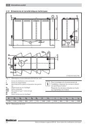
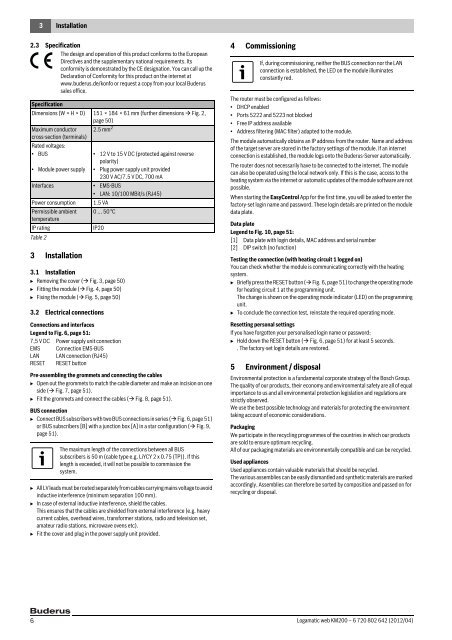
3 Installation2.3 SpecificationThe design and operation of this product conforms to the EuropeanDirectives and the supplementary national requirements. Itsconformity is demonstrated by the CE designation. You can call up theDeclaration of Conformity for this product on the internet atwww.buderus.de/konfo or request a copy from your local Buderussales office.SpecificationDimensions (W × H × D) 151 × 184 × 61 mm (further dimensions Fig. 2,page 50)Maximum conductor 2.5 mm 2cross-section (terminals)Rated voltages:• BUS• Module power supply3 Installation3.1 InstallationB Removing the cover ( Fig. 3, page 50)B Fitting the module ( Fig. 4, page 50)B Fixing the module ( Fig. 5, page 50)3.2 Electrical connectionsConnections and interfacesLegend to Fig. 6, page 51:7,5 V DC Power supply unit connectionEMS Connection EMS-BUSLAN LAN connection (RJ45)RESET RESET button• 12 V to 15 V DC (protected against reversepolarity)• Plug power supply unit provided230 V AC/7.5 V DC, 700 mAInterfaces • EMS-BUS• LAN: 10/100 MBit/s (RJ45)Power consumption 1.5 VAPermissible ambient 0 ... 50 °CtemperatureIP ratingIP20Table 2Pre-assembling the grommets and connecting the cablesB Open out the grommets to match the cable diameter and make an incision on oneside ( Fig. 7, page 51).B Fit the grommets and connect the cables ( Fig. 8, page 51).BUS connectionB Connect BUS subscribers with two BUS connections in series ( Fig. 6, page 51)or BUS subscribers [B] with a junction box [A] in a star configuration ( Fig. 9,page 51).The maximum length of the connections between all BUSsubscribers is 50 m (cable type e.g. LiYCY 2 x 0.75 (TP)). If thislength is exceeded, it will not be possible to commission thesystem.B All LV leads must be routed separately from cables carrying mains voltage to avoidinductive interference (minimum separation 100 mm).B In case of external inductive interference, shield the cables.This ensures that the cables are shielded from external interference (e.g. heavycurrent cables, overhead wires, transformer stations, radio and television set,amateur radio stations, microwave ovens etc).B Fit the cover and plug in the power supply unit provided.4 CommissioningIf, during commissioning, neither the BUS connection nor the LANconnection is established, the LED on the module illuminatesconstantly red.The router must be configured as follows:• DHCP enabled• Ports 5222 and 5223 not blocked• Free IP address available• Address filtering (MAC filter) adapted to the module.The module automatically obtains an IP address from the router. Name and addressof the target server are stored in the factory settings of the module. If an internetconnection is established, the module logs onto the Buderus-Server automatically.The router does not necessarily have to be connected to the internet. The modulecan also be operated using the local network only. If this is the case, access to theheating system via the internet or automatic updates of the module software are notpossible.When starting the EasyControl App for the first time, you will be asked to enter thefactory-set login name and password. These login details are printed on the moduledata plate.Data plateLegend to Fig. 10, page 51:[1] Data plate with login details, MAC address and serial number[2] DIP switch (no function)Testing the connection (with heating circuit 1 logged on)You can check whether the module is communicating correctly with the heatingsystem.B Briefly press the RESET button ( Fig. 6, page 51) to change the operating modefor heating circuit 1 at the programming unit.The change is shown on the operating mode indicator (LED) on the programmingunit.B To conclude the connection test, reinstate the required operating mode.Resetting personal settingsIf you have forgotten your personalised login name or password:B Hold down the RESET button ( Fig. 6, page 51) for at least 5 seconds.. The factory-set login details are restored.5 Environment / disposalEnvironmental protection is a fundamental corporate strategy of the Bosch Group.The quality of our products, their economy and environmental safety are all of equalimportance to us and all environmental protection legislation and regulations arestrictly observed.We use the best possible technology and materials for protecting the environmenttaking account of economic considerations.PackagingWe participate in the recycling programmes of the countries in which our productsare sold to ensure optimum recycling.All of our packaging materials are environmentally compatible and can be recycled.Used appliancesUsed appliances contain valuable materials that should be recycled.The various assemblies can be easily dismantled and synthetic materials are markedaccordingly. Assemblies can therefore be sorted by composition and passed on forrecycling or disposal.6<strong>Logamatic</strong> <strong>web</strong> <strong>KM200</strong> – 6 720 802 642 (2012/04)