SERVICE MANUAL - Nexo
SERVICE MANUAL - Nexo
SERVICE MANUAL - Nexo
- No tags were found...

You also want an ePaper? Increase the reach of your titles
YUMPU automatically turns print PDFs into web optimized ePapers that Google loves.
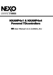
NXAMP4x4KJIHGFEDCBA■ BLOCK DIAGRAM 1/5 1AC SupplyPower Supply BlockSee Page. 5Power Switch*1234Inter-Block SignalsINANH -> CONTROLANA_IN[1:4]Analog Audio SignalsPAANH -> CONTROLTEMP_PA[1:4]Temperature Data of Power Amplifier UnitsCLIP_PA[1:4]Clip Signals of Power Amplifier UnitsOUTANH -> CONTROLSENSE_U[1:4]SenseBack Signals of Amplifier Output VoltageSENSE_I[1:4]SenseBack Signals of Amplifier Output CurrentPSANHA. PSANHB -> COLNTROMAINS_AMAINS DataMAINS_BPSW_DETECTStatus of Power SwitchTEMP_PS_A[1:2]Temperature Signals of Power Supply UnitsTEMP_PS_B[1:2]VOLTAGE_PS_A[1:2]Output Voltage data of Power Supply UnitsVOLTAGE_PS_B[1:2]CONTROL -> PAANHANA-OUT[1:4]Analog Audio SignalsRELAY_PA1[1:4] Control Signals for Relays on Power Amplifier UnitsCONTROL -> OUTANHRELAY_OUT[1:4] Control Signals for Output RelaysCONTROL -> PSANHA, PSANHBRELAY_PS_A[1:2]Control Signals for Relays on Power Supply UnitRELAY_PS_B[1:2]SHUTDOWN_PS_AShutdown Signals for Power Supply CiricuitsSHUTDOWN_PS_BANALOG AUDIO INPUTs[+28dBu]MAXChannel 1Channel 2Channel 3Channel 4Analog Input BlockGAIN: -14dB+9AEMCBAFILTER-9AGAIN: -14dB+9AEMCBAFILTER-9AGAIN: -14dB+9AEMCBAFILTER-9AGAIN: -14dB+9AEMCBAFILTER-9AANALOG AUDIOANALOG AUDIO Signals[+14dBu]MAXANA_IN1AGND1ANA_IN2AGND2ANA_IN3AGND3ANA_IN4AGND4+9AAGND-9AControl BlockSee Page. 7+24A_B+24A_A+15A+5A-15AAGNDPA CONTROLRELAY_PA1ANALOG AUDIOANA_OUT1AGND1PA DATATEMP_PA1CLIP_PA1PA CONTROLRELAY_PA2ANALOG AUDIOANA_OUT2AGND2PA DATATEMP_PA2CLIP_PA2+5AAGND+B_A1+E_A1+15+E_A1PGND_A1-B_A1-E_A1+15-E_A1+5AAGND+B_A2+E_A2+15+_A2EPGND_A2-B_A2-E_A2+15-E_A2+5AAGNDPower Amplifier BlockSee Page. 6Power Amplifier BlockSee Page. 6POUT1POUT2Output BlockSee Page. 6FAN_CONTROL_[1:2]PAANH -> OUTPAHPOUT[1:4]FAN speed control signalsOutput of Power Amplifier UnitsCONNECTION POINTofAGND[1:4] & AGNDUser Interface BlockSee Page. 7(LCD,SW,Encorder,LED...)PA CONTROLRELAY_PA3+B_B1+E_B1+15+E_B1PGND_B1POUT3ReferencePointOfGroundingANALOG AUDIOANA_OUT3AGND3Power Amplifier BlockSee Page. 656Power Supply Lines+24A_A+24A_B+15A+9A+5A-9A-15A+5D+3.3D+B_A[1:2]+B_B[1:2]-B_A[1:2]-B_B[1:2]+E_A[1:2]+15+E_B[1:2]+15+E_A[1:2]+E_B[1:2]-E_A[1:2]+15-E_B[1:2]+15-E_A[1:2]-E_B[1:2]for Small Signal Analog Circuitsfor Digital CircuitsPositive Rail Voltage Line for Power Amplifier UnitsNegative Rail Voltage Line for Power Amplifier UnitsFor EEEngine DriveRS232 BLOCKGPI BLOCKES(OPTION)AC SupplyOUT RELAY CONTROLRELAY_OUT1RELAY_OUT2RELAY_OUT3RELAY_OUT4SENSE BACK SIGNALSSENSE_U1SENSE_U2SENSE_U3SENSE_U4SENSE_I1SENSE_I2SENSE_I3SENSE_I4CONNECTIONPOINTBetweenDGND & AGNDPA DATATEMP_PA3CLIP_PA3PA CONTROLRELAY_PA4ANALOG AUDIOANA_OUT4AGND4PA DATATEMP_PA4CLIP_PA4-_B1B-E_B1+15-E_B1+5AAGND+B_B2+E_B2+15+E_B2PGND_B2-B_B2-E_B2+15-E_B2Power Amplifier BlockSee Page. 6POUT47GND LinesAGND[1:4]AGNDDGNDfor Analog Audio Signals of Each Channnelfor Common Analog Circuitsfor Digital Circuits*1Power SwitchPower Supply BlockSee Page. 5PGND_A[1:2]PGND_B[1:2]Reference Voltage of Main Power Supplies8Note: *1) Two power switches drawn in this block diagram are included in one device of a parallel type.28CA1-2001022110-104