SERVICE MANUAL - Nexo
SERVICE MANUAL - Nexo
SERVICE MANUAL - Nexo
- No tags were found...

You also want an ePaper? Increase the reach of your titles
YUMPU automatically turns print PDFs into web optimized ePapers that Google loves.
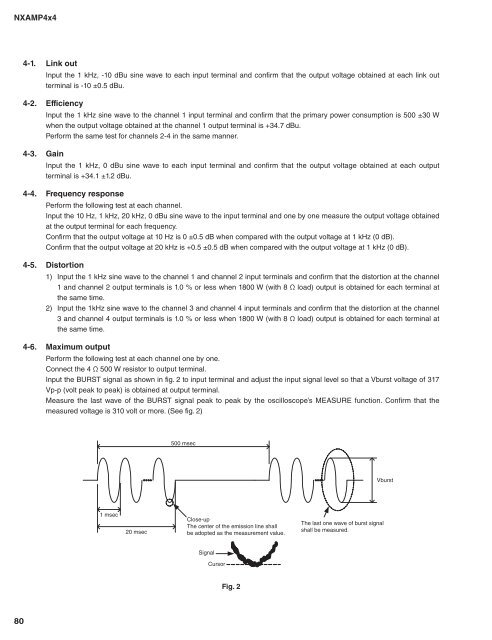
NXAMP4x44-1. Link outInput the 1 kHz, -10 dBu sine wave to each input terminal and confirm that the output voltage obtained at each link outterminal is -10 ±0.5 dBu.4-2. EfficiencyInput the 1 kHz sine wave to the channel 1 input terminal and confirm that the primary power consumption is 500 ±30 Wwhen the output voltage obtained at the channel 1 output terminal is +34.7 dBu.Perform the same test for channels 2-4 in the same manner.4-3. GainInput the 1 kHz, 0 dBu sine wave to each input terminal and confirm that the output voltage obtained at each outputterminal is +34.1 ±1.2 dBu.4-4. Frequency responsePerform the following test at each channel.Input the 10 Hz, 1 kHz, 20 kHz, 0 dBu sine wave to the input terminal and one by one measure the output voltage obtainedat the output terminal for each frequency.Confirm that the output voltage at 10 Hz is 0 ±0.5 dB when compared with the output voltage at 1 kHz (0 dB).Confirm that the output voltage at 20 kHz is +0.5 ±0.5 dB when compared with the output voltage at 1 kHz (0 dB).4-5. Distortion1) Input the 1 kHz sine wave to the channel 1 and channel 2 input terminals and confirm that the distortion at the channel1 and channel 2 output terminals is 1.0 % or less when 1800 W (with 8 Ω load) output is obtained for each terminal atthe same time.2) Input the 1kHz sine wave to the channel 3 and channel 4 input terminals and confirm that the distortion at the channel3 and channel 4 output terminals is 1.0 % or less when 1800 W (with 8 Ω load) output is obtained for each terminal atthe same time.4-6. Maximum outputPerform the following test at each channel one by one.Connect the 4 Ω 500 W resistor to output terminal.Input the BURST signal as shown in fig. 2 to input terminal and adjust the input signal level so that a Vburst voltage of 317Vp-p (volt peak to peak) is obtained at output terminal.Measure the last wave of the BURST signal peak to peak by the oscilloscope’s MEASURE function. Confirm that themeasured voltage is 310 volt or more. (See fig. 2)500 msecVburst1 msec20 msecClose-upThe center of the emission line shallbe adopted as the measurement value.The last one wave of burst signalshall be measured.SignalCursorFig. 280