

Radio Broadcast - 1923, August - 86 Pages, 8.5 ... - VacuumTubeEra
Radio Broadcast - 1923, August - 86 Pages, 8.5 ... - VacuumTubeEra
Radio Broadcast - 1923, August - 86 Pages, 8.5 ... - VacuumTubeEra
- No tags were found...

Create successful ePaper yourself
Turn your PDF publications into a flip-book with our unique Google optimized e-Paper software.
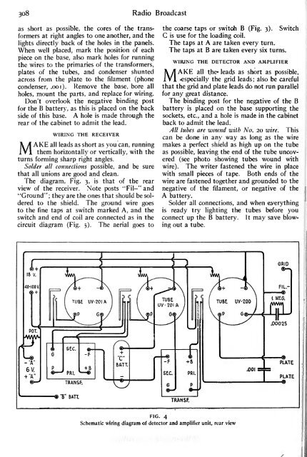
308 <strong>Radio</strong> <strong>Broadcast</strong>as short as possible, the cores of the transformersat right angles to one another, and the C is use for the loading coil.the coarse taps or switch B (Fig. 3). Switchlights directly back of the holes in the panels. The taps at A are taken every turn.When well placed, mark the position of each The taps at B are taken every six turns.piece on the base, also mark holes for runningthe wires to the primaries of the WIR.ING THE DETECTOR AND AMPLIFIERtransformers,switch and end of coil are connected as in the connect up the B battery. It may save blow-circuit diagram (Fig. 5). The aerial goes toplates of the tubes, and condenser shuntedacross from the plate to the filament (phone MAKE all the- leads as short as possible,especially the grid leads; also be carefulcondenser, .001). Remove the base, bore all that the grid and plate leads do not run parallelholes, mount the parts, and replace for wiring. for any great distance.Don't overlook the negative binding post The binding post for the negative of the Bfor the B battery, as this isplaced on the back battery is placed on the base supportingside of this base. A hole is made through the sockets, etc., and a hole is made in the cabinetrear of the cabinet to admit the lead.WIRING THE RECEIVERback to admit the lead.All tubes are wound with No. 20 wire. Thiscan be done in any way as long as the wireMAKE all leads as short as you can, running makes a perfect shield as high up on the tubethem horizontally or vertically, with the as possible, leaving the end of the tube uncoveredturns forming sharp right angles.(see photo showing tubes wound withturns Solder all connections possible, and be sure wire). The writer fastened the wire in placethat all unions are good and clean.with small pieces of tape. Both ends of theThe diagram, Fig. 3, is that of the rear wire are fastened together and grounded to theview of the receiver. Note posts "Fil-"and negative of the filament, or negative of the"Ground" ; they are the ones that should be solderedto the shield. The ground wire goes Solder all connections, and when everythingA battery.to the fine taps at switch marked A, and the isready try lighting the tubes before youing out a tube.TRANSF.FIG. 4Schematic wiring diagram of detector and amplifier unit, rear view


