

Radio Broadcast - 1923, August - 86 Pages, 8.5 ... - VacuumTubeEra
Radio Broadcast - 1923, August - 86 Pages, 8.5 ... - VacuumTubeEra
Radio Broadcast - 1923, August - 86 Pages, 8.5 ... - VacuumTubeEra
- No tags were found...

You also want an ePaper? Increase the reach of your titles
YUMPU automatically turns print PDFs into web optimized ePapers that Google loves.
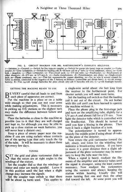
A Neighbor atThree Thousand Miles30CJWV\M 10FIG. 5.CIRCUIT DIAGRAM FOR MR. BARTHOLOMEW S COMPLETE RECEIVERI Antenna; 2 Ground; 3 Switch for fine taps.on coupler; 4 Switch for coarse (six turns) taps on coupler; 5 Variocoupler;6 Grid variometer; 7 Switch for loading coil; 8 6o-turn coil on 4" tube; 9 Grid condenser, .00025; IO Gridleak, megohm; 11 Plate variometer; 12 Two-circuit jack; i 13 UV-2OO tube; 14 Bradleystat; 15 Bradleystats orother rheostats; 16 UV-2OI or UV-2OI-A; 17 Audio transformers; 18 Potentiometer, 200 ohms; 19 Single-circuitjack; 20 Phone condenser, .001; 21 This line represents, the copper shielding; 22 No. 20 wire is wound around thetubes as shields, connected to the negative of the A battery or filament (connection not shown here); A 6-volt storagebattery; B Two 24-volt storage batteries for plate circuit (dry-cell B batteries will do); C 4-volt flashlight batteryGETTING THE MACHINE READY TO USEVERY careful that all leads to and fromBEeach piece of apparatus are correct.Put the machine in a place or on a tablewide enough so that you can rest your armswhile making adjustments. This is necessarypicking up DX stations as the slighest turnmay make the difference between failure andsuccess.Place the batteries as close to the machine aspossible (see to it that they are well chargedand kept so, for although you may be able topick up a close station on weak batteries, youwill never hear a distant one).Keep a piece of emery paper near the machineifyou are using sockets whose contactsare of the spring type that only touch the tipof the tube. It will be necessary to clean thesetips every few days.TUNINGSET the grid and plate variometer dials sothat the rotors are at right angles to thewindings of the stators.Set the coupler dial so that the windings ofstator and rotor are nearly parallel.Leave itin this position until the last when a slightchange may increase the signals.Set the coupler taps switch so that therewill be about 24 turns used. This applies toa single-wire aerial about 160 feet long fromthe receiver to the furthermost point. Forshorter aerials you will need more turns.Set the loading coil switch so that the loadingcoil is cut out of the circuit. Do not botherwith this coil until you have learned to operatethe machine without it.the first-stage jackPlace the phone plug inand turn on the amplifying tube, slightly for aUV-20I-A and almost full for a UV-2OI . Nowlight the detector tube which is controlled withthe Bradleystat. This should be turned onuntil you hear a hissing in the phones. Thenturn it back a slight fraction of a turn.The potentiometeris turned to approximatelythe middle point if using about 18 voltson the plate of the detector.Now rotate the grid variometer toward theleft, slowly, and listen for the whistling thatindicates a broadcasting station. If you haveto move it a great distance then a slight adjustmentof the plate variometer may be necessaryto keep the tube near the hiss.When a signal is heard, readjust the filamentsof the amplifier and detector tubes untilthe signal is strongest, using the least currentnecessary. Now readjust the variometersusing the verniers and always keeping thestation within hearing. Usually this willmean turningfirst one and then the otherdial toward the left. At some point youwill


