

Radio Broadcast - 1923, August - 86 Pages, 8.5 ... - VacuumTubeEra
Radio Broadcast - 1923, August - 86 Pages, 8.5 ... - VacuumTubeEra
Radio Broadcast - 1923, August - 86 Pages, 8.5 ... - VacuumTubeEra
- No tags were found...

You also want an ePaper? Increase the reach of your titles
YUMPU automatically turns print PDFs into web optimized ePapers that Google loves.
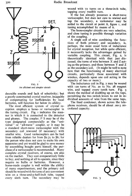
circuit,32O<strong>Radio</strong> <strong>Broadcast</strong>wound with 72 turns on a three-inch tube,tapping every twelfth turn.If the fan already possesses a short-wavevariocoupler, but does not care to rewind andtap the secondary, a variometer may beadded to the circuit at point A, figure i, andFIG. 2An efficient and simpler circuitdesirable sounds and lack of selectivity; buta poorly constructed crystal receiver, incapableof compensating for inefficiencies by localbatteries, will function far below its ability.The most efficient system of crystal receptionemploys a loose- or variocoupler inthe tuning circuit. Fig.i indicates the mannerin which it is connected to the detectorand phones. The coupler, P S may be of thetype designated commercially as the "universal"or "all-wave" coupler, or itmay bea standard short-wave variocoupler with thesecondary coil rewound (if necessary) withsmaller wire. Good variocouplers can be hadfrom reliable dealers for from $2.75 to $6; forthe person who does not care to make his ownapparatus and yet would be glad to save moneyby assembling bought parts himself, the purchaseof a variocoupleris recommended .Manycomplete crystal receivers, of course, are alsoon the market. They cost comparatively littleto buy, and nothing at all to operate, since theyrequire no bulbs or batteries. However, ahome-made coupleris well within the abilityof many experimenters, and the primary coilshould be wound with 6oturns of any convenientwire on a three-and-a-half-inch tube, tappedevery sixth turn. The secondary may betuning accomplished by means of it.The loose-coupler circuits are very selective,and close tuning is possible through variationof the coupling.A single coil of wire combining the functionsof both primary and secondary, is,perhaps, the more usual form of inductancefor crystal reception, but while quite efficient,itnecessarily lacks the advantages gained byvariable coupling. This.Fig. 2, istheoretically identical with that just discussed,the turns of wire between X and Z actingas the primary, and those between Y and Zas the secondary coil. ( It might be well to notehere that the functioning of many electricalcircuits, particularly those associated withwireless, depends upon one coil acting in thecapacity of two or more.)The inductance coil in Fig. 2 may be woundwith 1 20 turns of No. 20 to No. 28 magnetwire, and tapped every tenth turn. Fig. 3shows the method of doubling up on the taps,permitting the two switch levers to cut in individualamounts of wire from the same taps.The fixed condenser, shown across the telephonereceivers, should be of about .0015 microfaradcapacity.FIG. 3


