Porosity Aware Buffered Steiner Tree Construction - Computer ...
Porosity Aware Buffered Steiner Tree Construction - Computer ...
Porosity Aware Buffered Steiner Tree Construction - Computer ...

You also want an ePaper? Increase the reach of your titles
YUMPU automatically turns print PDFs into web optimized ePapers that Google loves.
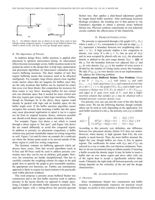
IEEE TRANSACTIONS ON COMPUTER-AIDED DESIGN OF INTEGRATED CIRCUITS AND SYSTEMS, VOL. XX, NO. Y, MONTH 2003 101000000000111111111000000000111111111000000000111111111000000000111111111000000000111111111Sink000000000011111111110000000000111111111100000000001111111111000000000011111111110000000000111111111100000000001111111111000000000011111111110000000000111111111100000000001111111111Buffer(a)SinkSource00000000111111110000000011111111000000001111111100000000111111110000000011111111SinkSink000000000001111111111100000000000111111111110000000000011111111111000000000001111111111100000000000111111111110000000000011111111111000000000001111111111100000000000111111111110000000000011111111111Buffer(b)SourceFig. 2. An arbitrary <strong>Steiner</strong> tree as shown in (a) may force wires to passthrough routing congested regions. A congestion aware buffered <strong>Steiner</strong> tree,which is shown in (b), will may let wires go through sparse regions.B. The Importance of <strong>Porosity</strong>In tradition design flows, buffer insertion is applied afterplacement to optimize interconnect timing. As interconnecteffects become increasingly severe, buffer insertion needs to bepushed up earlier in the design flow to help logic optimizationand placement algorithms on interconnect estimation and toreserve buffering resources. The sheer number of nets thatrequire buffering means that resources need to be allocatedintelligently. For example, large blocks placed close togethercreate narrow alleys that are magnets for buffers since theyare the only locations that buffers can be inserted for routesthat cross over these blocks. But competition for resources forthese routes is very fierce. Inserting buffers for less criticalnets can eliminate space that is needed for more critical netsthat may require gate sizing or other logic transforms. Further,though no blockages lie in the alleys, these regions couldalready be packed with logic and no feasible space for thebuffer might exist. If the buffer insertion algorithm cannotrecognize this scenario then inserting a buffer into this spacemay cause placement legalization to spiral it out to a regiontoo far from its original location. Hence, whenever possibleone should avoid denser regions unless absolutely critical.For example, Figure 1(a) shows a net which is routedthrough a dense region or “hot spot”, and Figure 1(b) showsthe net routed differently to avoid this congested region.In addition to porosity (or placement congestion), a buffersolution may generate remarkable impact on wiring congestionas well. Figure 2 (a) and (b) show an example for a multi-pinnet where the <strong>Steiner</strong> point needs to be moved outside of thedense region to yield less wiring congestion.The literature contains no buffering approach which addressesthese issues. Note that several algorithms (such asS-<strong>Tree</strong> and SP-<strong>Tree</strong>) could be used to address porosity constraintssince they can be run on arbitrary grid graphs. However,the extensions are hardly straightforward. One has tocarefully consider the weighting scheme for edges in the gridgraph, how to sparsify the graph to give reasonable runtimes,the appropriate cost functions, etc. Further, any simultaneousapproach is likely to require too much runtime to be practicallyused within physical synthesis.This work proposes a porosity aware buffered <strong>Steiner</strong> treeconstruction and is the first buffer insertion work to addressporosity in the layout directly (as opposed to simply specifyinga handful of allowable buffer insertion locations). Theapproach begins with a timing-driven but porosity-ignorant<strong>Steiner</strong> tree, then applies a plate-based adjustment guidedby length based buffer insertion. After performing localizedblockage avoidance, the resulting tree is then passed to vanGinneken’s algorithm to obtain a porosity aware buffered<strong>Steiner</strong> tree. Physical synthesis experiments on real industrialcircuits confirms the effectiveness of this framework.II. PROBLEM FORMULATIONThe porosity is represented through a tile graph G(V G ,E G )where a node g ∈ V G corresponds to a tile and an edge e uv ∈E G represents a boundary between two neighboring tiles uand v ∈ V G . A high porosity implies a low congestion ordensity, vice versa. If a tile g ∈ V G has an area of A(g)and its area occupied by placed cells are a(g), the placementdensity is defined as the area usage density d(g) = a(g)A(g)oftile g. For the boundary between two adjacent tiles g i andg j , its wire density d(g i ,g j ) is the number of wires across itdivided by the number of wiring tracks across this boundary.We take d 2 (g i ,g j ) as wire density cost in our implementation.We address the following problem:<strong>Porosity</strong>-aware <strong>Buffered</strong> <strong>Steiner</strong> <strong>Tree</strong> Problem: Givena net N = {v 0 ,v 1 ,...,v n } with source v 0 and sinks{v 1 ,...,v n }, load capacitance c(v i ) and required arrival timeq(v i ) for 1 ≤ i ≤ n, tile graph G(V G ,E G ), and a buffer type b,construct a <strong>Steiner</strong> tree T (V,E), in which V = N ∪ V <strong>Steiner</strong>and edges in E span every node in V , such that a bufferinsertion solution that satisfies q(v i ) may be obtained with aminimal porosity cost(wire density cost).For porosity cost, one can sum the costs of the tiles that theroutes cross. We use the following function, though certainlyothers can be used as well, depending on the application. Foreach buffer inserted in a tile g, the porosity cost p(g) is definedas:⎧⎨0.5 : d(g) ≤ 0.5p(g) = 4d 2 (g) − 2d(g)+0.5 : 0.5