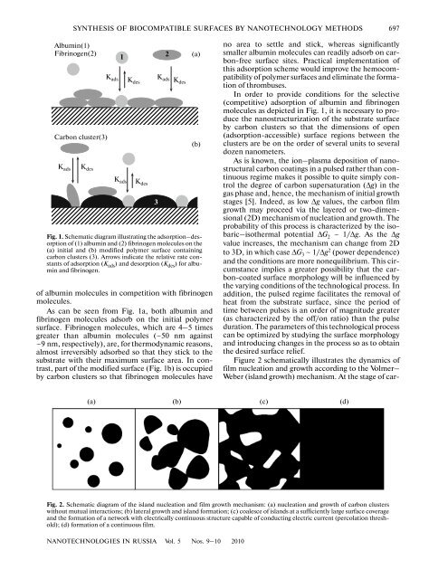
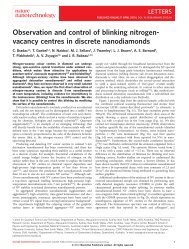
SYNTHESIS OF BIOCOMPATIBLE SURFACES BY NANOTECHNOLOGY METHODS 697Albumin(1)Fibrinogen(2)Carbon cluster(3)K ads K desK ads K desK ads K desK ads Kdes1<strong>of</strong> albumin molecules in competition with fibrinogenmolecules.As can be seen from Fig. 1a, both albumin andfibrinogen molecules adsorb on the initial polymersurface. Fibrinogen molecules, which are 4–5 timesgreater than albumin molecules (~50 nm against~9 nm, respectively), are, for thermodynamic reasons,almost irreversibly adsorbed so that they stick to thesubstrate with their maximum surface area. In contrast,part <strong>of</strong> the modified surface (Fig. 1b) is occupied<strong>by</strong> carbon clusters so that fibrinogen molecules have(a)(b)Fig. 1. Schematic diagram illustrating the adsorption–desorption<strong>of</strong> (1) albumin and (2) fibrinogen molecules on the(a) initial and (b) modified polymer surface containingcarbon clusters (3). Arrows indicate the relative rate constants<strong>of</strong> adsorption (K ads ) and desorption (K des ) for albuminand fibrinogen.32no area to settle and stick, whereas significantlysmaller albumin molecules can readily adsorb on carbon-freesurface sites. Practical implementation <strong>of</strong>this adsorption scheme would improve the hemocompatibility<strong>of</strong> polymer <strong>surfaces</strong> and eliminate the formation<strong>of</strong> thrombuses.In order to provide conditions for the selective(competitive) adsorption <strong>of</strong> albumin and fibrinogenmolecules as depicted in Fig. 1, it is necessary to producethe nanostructurization <strong>of</strong> the substrate surface<strong>by</strong> carbon clusters so that the dimensions <strong>of</strong> open(adsorption-accessible) surface regions between theclusters are be on the order <strong>of</strong> several units to severaldozen nanometers.As is known, the ion–plasma deposition <strong>of</strong> nanostructuralcarbon coatings in a pulsed rather than continuousregime makes it possible to quite simply controlthe degree <strong>of</strong> carbon supersaturation (Δg) in thegas phase and, hence, the mechanism <strong>of</strong> initial growthstages [5]. Indeed, as low Δg values, the carbon filmgrowth may proceed via the layered or two-dimensional(2D) mechanism <strong>of</strong> nucleation and growth. Theprobability <strong>of</strong> this process is characterized <strong>by</strong> the isobaric–isothermalpotential ΔG 2 ~ 1/Δg. As the Δgvalue increases, the mechanism can change from 2Dto 3D, in which case ΔG 3 ~ 1/Δg 2 (power dependence)and the conditions are more nonequilibrium. This circumstanceimplies a greater possibility that the carbon-coatedsurface morphology will be influenced <strong>by</strong>the varying conditions <strong>of</strong> the technological process. Inaddition, the pulsed regime facilitates the removal <strong>of</strong>heat from the substrate surface, since the period <strong>of</strong>time between pulses is an order <strong>of</strong> magnitude greater(as characterized <strong>by</strong> the <strong>of</strong>f/on ratio) than the pulseduration. The parameters <strong>of</strong> this technological processcan be optimized <strong>by</strong> studying the surface morphologyand introducing changes in the process so as to obtainthe desired surface relief.Figure 2 schematically illustrates the dynamics <strong>of</strong>film nucleation and growth according to the Volmer–Weber (island growth) mechanism. At the stage <strong>of</strong> car-(a) (b) (c) (d)Fig. 2. Schematic diagram <strong>of</strong> the island nucleation and film growth mechanism: (a) nucleation and growth <strong>of</strong> carbon clusterswithout mutual interactions; (b) lateral growth and island formation; (c) coalesce <strong>of</strong> islands at a sufficiently large surface coverageand the formation <strong>of</strong> a network with electrically continuous structure capable <strong>of</strong> conducting electric current (percolation threshold);(d) formation <strong>of</strong> a continuous film.NANOTECHNOLOGIES IN RUSSIA Vol. 5 Nos. 9–10 2010
698ALEKHIN et al.bon coating formation, it is necessary to determine theso-called percolation threshold (see Fig. 2c), where<strong>by</strong>a carbon network that forms an electrically continuousstructure capable <strong>of</strong> conducting electric current isformed, typically when the substrate is covered up to70–80%. Why is determining the percolation thresholdso important? Because this point at the stage <strong>of</strong>carbon deposition corresponds to the formation <strong>of</strong> amosaic carbon nanostructure with cluster dimensionsin a nanometer range. This situation leads to a changein the physicochemical and biomedical properties,thus making it possible to control the hemocompatibility<strong>of</strong> the carbon-modified surface [7, 8]. It is highlyprobable that the percolation threshold determines thefinal stage <strong>of</strong> formation <strong>of</strong> a hemocompatible mosaiccluster structure on the substrate surface. In this study,the percolation threshold was determined as a function<strong>of</strong> the number N and the repetition frequency f <strong>of</strong>pulses <strong>of</strong> the carbon plasma generator. The thickness<strong>of</strong> the deposited carbon coating varied within 0.3–15 nm. The proposed technology was experimentallyimplemented and patented [6].DETERMINING THE TECHNOLOGICALPARAMETERS AND PHYSICALAND BIOMEDICAL PROPERTIESOF PLASMA-DEPOSITED CARBONNANOSTRUCTURESWe have experimentally determined the optimumtechnological parameters for the process <strong>of</strong> LDPE andPU modification <strong>by</strong> carbon clusters to reach a percolationthreshold as the pulse repetition frequency f =1 Hz and their number N = 50, which corresponded toan effective carbon coating thickness <strong>of</strong> ~7.5 nm. Thesurface morphology <strong>of</strong> samples was studied <strong>by</strong> scanningelectron microscopy (SEM) and scanning probemicroscopy (SPM).The SEM measurements were performed on aCamscan 4 (Cambridge Instruments) microscopewith a typical magnification <strong>of</strong> ×1000–5000, whichcorresponds to the size <strong>of</strong> visible fields on a level <strong>of</strong>several tens <strong>of</strong> microns. By studying the characteristicfeatures <strong>of</strong> morphology, it is possible to evaluate theoptimum technological parameters, introduce thenecessary corrections, and obtain the surface reliefnecessary for further research. It was established thatthe relief <strong>of</strong> modified polymer <strong>surfaces</strong> was significantlydependent on the number N <strong>of</strong> carbon plasmapulses and their repetition frequency f. The dynamics<strong>of</strong> variation <strong>of</strong> the surface relief exhibited the followingtrends. At a small amount <strong>of</strong> the deposited material(N = 2–10), the necessary surface morphology (correspondingto Fig. 2c) is not formed. In this case, thecarbon-modified polymer surface has a globular structure,i.e., exhibits separate clusters with dimensionswithin 100–200 nm. Large values <strong>of</strong> the pulse repetitionfrequency and number ( f ≥ 10 Hz, N ≥ 100) correspondedto the formation <strong>of</strong> structures representingeither fibrils (3000–4000 nm long) or continuouschains. The most favorable regimes were those with f =0.3–1.0 Hz and N = 30–50.Direct evidence for the formation <strong>of</strong> a carbon clusterstructure on the LDPE surface was provided <strong>by</strong> theresults <strong>of</strong> SPM investigations in air at room temperature.These measurements were performed on aSolver TM Pro M (NT-MDT Company) instrumentoperating in a tapping mode with 2D and 3D imaging.The cantilever had an elasticity coefficient <strong>of</strong> about20 N/m and a resonance frequency <strong>of</strong> 131.851 kHz;the point probe had a tip radius <strong>of</strong> several nanometers.The minimum spatial resolution <strong>of</strong> the microscope, asevaluated <strong>by</strong> the size <strong>of</strong> the minimum visible elements<strong>of</strong> the sample surface, was about 10 nm.Figures 3 and 4 present typical 2D images obtained<strong>by</strong> an SPM examination <strong>of</strong> LDPE and PU modified atvarious repetition frequencies ( f = 0.1–1.0 Hz) andnumbers (N = 30–50) <strong>of</strong> carbon plasma pulses. As thepulse repetition frequency was increased from 0.1 to1.0 Hz and/or their number was increased from 2 to50, the size <strong>of</strong> the deposited carbon clusters or theiraggregates, as well as the degree <strong>of</strong> surface coverage <strong>by</strong>carbon, increased to 70–80%. This led to the formation<strong>of</strong> a mosaic carbon network with an electricallyconducting structure.Thus, based on our results, it was concluded thatthe optimum pulse repetition frequency and carbondeposition velocity for the formation <strong>of</strong> the desiredcluster structure on the polymer surface are 0.3–1 Hzand 0.1–0.2 nm/s, respectively.Additional information on the structure <strong>of</strong> modifiedcarbon coatings on polymer substrates wasobtained <strong>by</strong> mathematically processing their Ramanspectra [9]. An analysis <strong>of</strong> parameters such as theRaman shift and the heights and widths <strong>of</strong> model spectrumcomponents (Fig. 5), which were determinedusing the results <strong>of</strong> Tamba et al. [10], allowed us tomake the following conclusions concerning the structure<strong>of</strong> layers formed on polymer substrates. It was evidentthat both sp 2 and sp 3 hybridization is present incarbon deposits. According to the general principles <strong>of</strong>thermodynamics, structural elements with the sp 2 type<strong>of</strong> hybridization form small-size clusters. Of all thepossible clusters <strong>of</strong> this kind, the most probable aresix-member rings, which can be either separate orconnected into sets <strong>of</strong> several rings. These rings maypossess angular misorientation and can be shaped likeirregular hexagons. These clusters are bound <strong>by</strong> elements<strong>of</strong> the sp 3 hybridization and can be chaoticallyoriented relative to each other.Medico-technical investigations were performed atthe Research Institute <strong>of</strong> Transplantology and ArtificialOrgans (Ministry <strong>of</strong> Public Health <strong>of</strong> the RussianFederation, Moscow), which involved (i) an analysis<strong>of</strong> the thrombocyte adhesion with allowance for theirmorphological characteristics and (ii) a determinationNANOTECHNOLOGIES IN RUSSIA Vol. 5 Nos. 9–10 2010