SH564128FH8N0QHSCR - Itautec
SH564128FH8N0QHSCR - Itautec
SH564128FH8N0QHSCR - Itautec
- No tags were found...
Create successful ePaper yourself
Turn your PDF publications into a flip-book with our unique Google optimized e-Paper software.
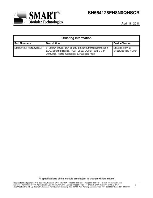
<strong>SH564128FH8N0QHSCR</strong>April 11, 2011Ordering InformationPart Numbers Description Device Vendor<strong>SH564128FH8N0QHSCR</strong> 512Mx64 (4GB), DDR3, 240-pin Unbuffered DIMM, Non-ECC, 256Mx8 Based, PC3-10600, DDR3-1333-9-9-9,30.00mm, RoHS Compliant & Halogen-Free.SMART, Rev. CS4B2G0846C-HCH9(All specifications of this module are subject to change without notice.)Corporate Headquarters: P. O. Box 1757, Fremont, CA 94538, USA • Tel:(510) 623-1231 • Fax:(510) 623-1434 • E-mail: info@smartm.comEurope: 5 Kelvin Park South, Kelvin South, East Kilbride, G75 ORH, United Kingdom • Tel: +44-870-870-8747 • Fax: +44-870-870-8757Asia/Pacific: Plot 18, Lrg Jelawat 4, Kawasan Perindustrian Seberang Jaya 13700, Prai, Penang, Malaysia • Tel: +604-3992909 • Fax: +604-39929031
<strong>SH564128FH8N0QHSCR</strong>April 11, 2011• April 11, 2011Corrected part number to <strong>SH564128FH8N0QHSCR</strong>.• January 25, 2011Datasheet released.Revision HistoryCorporate Headquarters: P. O. Box 1757, Fremont, CA 94538, USA • Tel:(510) 623-1231 • Fax:(510) 623-1434 • E-mail: info@smartm.comEurope: 5 Kelvin Park South, Kelvin South, East Kilbride, G75 ORH, United Kingdom • Tel: +44-870-870-8747 • Fax: +44-870-870-8757Asia/Pacific: Plot 18, Lrg Jelawat 4, Kawasan Perindustrian Seberang Jaya 13700, Prai, Penang, Malaysia • Tel: +604-3992909 • Fax: +604-39929032
<strong>SH564128FH8N0QHSCR</strong>April 11, 20114GByte (512Mx64) DDR3 SDRAM Module - 256Mx8 Based240-pin DIMM, Unbuffered, Non-ECCFeatures• Standard = JEDEC• Configuration = Non-ECC• Number of Module Ranks = 2• Number of Devices = 16• V DD = V DDQ = 1.5V• V DDSPD = 1.7V to 3.6V• Cycle Time = 1.5ns• CAS Latency = 6, 7, 8, 9• Additive Latency = 0, CL-1, and CL-2• CAS Write Latency (CWL) = 5, 6, 7• Burst Length = BC4, BL8, BC4 or BL8 (on the fly)• Burst Length = Nibble Sequential & Interleave Mode• Internal Banks per SDRAM = 8• Refresh = 8K/64ms• Device Package = FBGA• Lead Finish = Gold• Length x Height = 133.35mm x 30.00mm• No. of sides = Double-sided• Mating Connector (Examples)Vertical = AMP - 5-1932000-9• ZQ calibration supported• On chip DLL align DQ, DQS and DQS transitionwith CK transition• DM write data-in at both the rising and fallingedges of the data strobe• All addresses and control inputs latched on therising edges of the clock• Dynamic On Die Termination supported• Driver strength selected by EMRS• Asynchronous RESET pin supported• Write Levelization supported• 8-bit pre-fetchAddressingDevice Configuration256Mx8Number of Internal Banks 8Bank AddressBA0 - BA2Auto prechargeA10/APBC switch on the flyA12/BCRow AddressA0 - A14Column AddressA0 - A9Pin Description TableSymbol Type Polarity FunctionCK0~CK1,CK0~CK1SSTL_15DifferentialCrossingCK and CK are differential clock inputs. All the DDR3 SDRAM address/control inputs are sampledon the crossing of the positive edge of CK and the negative edge of CK. Output (read) datais referenced to the crossing of CK and CK (Both directions of crossing).CKE0, CKE1 SSTL_15 Active HighCS0, CS1 SSTL_15 Active LowODT0, ODT1 SSTL_15 Active HighActivates the SDRAM CK signal when high and deactivates the CK signal when low. By deactivatingthe clocks, CKE low initiates the Power Down mode, or the Self Refresh mode.Enables the associated SDRAM command decoder when low and disables the commanddecoder when high. When decoder is disabled, new commands are ignored but previous operationscontinue.This signal provides for external rank selection on systems with multiple ranks.When high, termination resistance is enabled for all DQ, DQS, DQS and DM pins, assumingthis function is enabled on the DRAM.BA0~BA2 SSTL_15 - Selects which SDRAM bank of the eight is activated.Corporate Headquarters: P. O. Box 1757, Fremont, CA 94538, USA • Tel:(510) 623-1231 • Fax:(510) 623-1434 • E-mail: info@smartm.comEurope: 5 Kelvin Park South, Kelvin South, East Kilbride, G75 ORH, United Kingdom • Tel: +44-870-870-8747 • Fax: +44-870-870-8757Asia/Pacific: Plot 18, Lrg Jelawat 4, Kawasan Perindustrian Seberang Jaya 13700, Prai, Penang, Malaysia • Tel: +604-3992909 • Fax: +604-39929033
<strong>SH564128FH8N0QHSCR</strong>April 11, 2011Pin Description Table (Contd.)Symbol Type Polarity FunctionA0~A14 SSTL_15 -During a Bank Activate command cycle, address inputs define the row address (RA0-RA14).During a Read or Write command cycle, address inputs define the column address (CA0-CA9).In addition to the column address, AP is used to invoke auto-precharge operation at the end ofthe burst read or write cycle. If AP is high, auto-precharge is selected and BA0, BA1, BA2defines the bank to be precharged. If AP is low, auto-precharge is disabled. During a Prechargecommand cycle, AP is used in conjunction with BA0, BA1, BA2 to control which bank(s) to precharge.If AP is high, all banks will be precharged regardless of the state of BA0, BA1 or BA2. IfAP is low, BA0, BA1 and BA2 are used to define which bank to precharge. A12(BC) is sampledduring READ and WRITE commands to determine if burst chop (on-the-fly) will be performed(HIGH, no burst chop; LOW, burst chopped).RAS, CAS, WE SSTL_15 Active Low RAS, CAS, and WE (along with CS) define the command being entered.DQ0~DQ63 SSTL_15 - Data Input/Output pins.DQS0~DQS7DQS0~DQS7SSTL_15DifferentialCrossingData strobe for input and output data.DM0~DM7 SSTL_15 Active HighSA0~SA2 -SDA -SCL -RESET CMOS Active LowV DD, V SS Supply -V DDQ Supply -DM is an input mask signal for write data. Input data is masked when DM is sampled high coincidentwith that input data during a write access. DM is sampled on both edges of DQS.Although DM pins are input only, the DM loading matches the DQ and DQS loading.These signals are tied at the system to either V SS or V DDSPD to configure the serial SPDEEPROM address range.This bidirectional pin is used to transfer data into or out of the SPD EEPROM. An external resistormay be connected from the SDA bus line to V DDSPD to act as a pullup on the system board.This signal is used to clock data into and out of the SPD EEPROM. An external resistor may beconnected from the SCL bus tied to V DDSPD to act as a pullup on the system board.Asynchronous Reset is active when RESET is LOW, and inactive when RESET is HIGH.RESET must be HIGH during normal operation. RESET is CMOS rail to rail signal with DC highand low at 80% and 20% of V DD .Power and ground for the DDR3 SDRAM input buffers, and core logic. V DD and V DDQ pins aretied to V DD /V DDQ planes on these modules. V SS pins are tied to V SS planes on these modules.Power supply for the DDR3 SDRAM output buffers to provide improved noise immunity. V DDQshares the same power plane as V DD pins.V REFDQ Supply Reference voltage for I/O inputs.V REFCA Supply - Reference voltage for address/command inputs.V DDSPD Supply -Power supply for SPD EEPROM. This supply is separate from the V DD /V DDQ power plane.EEPROM supply is operable from 1.7V to 3.6V.V TT Supply - Termination voltage for address/command/control/clock nets.NC - - No Connect.Corporate Headquarters: P. O. Box 1757, Fremont, CA 94538, USA • Tel:(510) 623-1231 • Fax:(510) 623-1434 • E-mail: info@smartm.comEurope: 5 Kelvin Park South, Kelvin South, East Kilbride, G75 ORH, United Kingdom • Tel: +44-870-870-8747 • Fax: +44-870-870-8757Asia/Pacific: Plot 18, Lrg Jelawat 4, Kawasan Perindustrian Seberang Jaya 13700, Prai, Penang, Malaysia • Tel: +604-3992909 • Fax: +604-39929034
<strong>SH564128FH8N0QHSCR</strong>April 11, 2011DDR3 240-pin DIMM Pin ListPinNoPinNamePinNoPinNamePinNoPinNamePinNoPinNamePinNoPinNamePinNoPinNamePinNoPinNamePinNoPinName1 V REFDQ 31 DQ25 61 A2 91 DQ41 121 V SS 151 V SS 181 A1 211 V SS2 V SS 32 V SS 62 V DD 92 V SS 122 DQ4 152 DM3 182 V DD 212 DM53 DQ0 33 DQS3 63 CK1 93 DQS5 123 DQ5 153 NC 183 V DD 213 NC4 DQ1 34 DQS3 64 CK1 94 DQS5 124 V SS 154 V SS 184 CK0 214 V SS5 V SS 35 V SS 65 V DD 95 V SS 125 DM0 155 DQ30 185 CK0 215 DQ466 DQS0 36 DQ26 66 V DD 96 DQ42 126 NC 156 DQ31 186 V DD 216 DQ477 DQS0 37 DQ27 67 V REFCA 97 DQ43 127 V SS 157 V SS 187 NC 217 V SS8 V SS 38 V SS 68 NC 98 V SS 128 DQ6 158 NC 188 A0 218 DQ529 DQ2 39 NC 69 V DD 99 DQ48 129 DQ7 159 NC 189 V DD 219 DQ5310 DQ3 40 NC 70 A10/AP 100 DQ49 130 V SS 160 V SS 190 BA1 220 V SS11 V SS 41 V SS 71 BA0 101 V SS 131 DQ12 161 NC 191 V DD 221 DM612 DQ8 42 NC 72 V DD 102 DQS6 132 DQ13 162 NC 192 RAS 222 NC13 DQ9 43 NC 73 WE 103 DQS6 133 V SS 163 V SS 193 CS0 223 V SS14 V SS 44 V SS 74 CAS 104 V SS 134 DM1 164 NC 194 V DD 224 DQ5415 DQS1 45 NC 75 V DD 105 DQ50 135 NC 165 NC 195 ODT0 225 DQ5516 DQS1 46 NC 76 CS1 106 DQ51 136 V SS 166 V SS 196 A13 226 V SS17 V SS 47 V SS 77 ODT1 107 V SS 137 DQ14 167 NC 197 V DD 227 DQ6018 DQ10 48 NC 78 V DD 108 DQ56 138 DQ15 168 RESET 198 NC 228 DQ6119 DQ11 49 NC 79 NC 109 DQ57 139 V SS 169 CKE1 199 V SS 229 V SS20 V SS 50 CKE0 80 V SS 110 V SS 140 DQ20 170 V DD 200 DQ36 230 DM721 DQ16 51 V DD 81 DQ32 111 DQS7 141 DQ21 171 A14 201 DQ37 231 NC22 DQ17 52 BA2 82 DQ33 112 DQS7 142 V SS 172 A15 (NC) 202 V SS 232 V SS23 V SS 53 NC 83 V SS 113 V SS 143 DM2 173 V DD 203 DM4 233 DQ6224 DQS2 54 V DD 84 DQS4 114 DQ58 144 NC 174 A12/BC 204 NC 234 DQ6325 DQS2 55 A11 85 DQS4 115 DQ59 145 V SS 175 A9 205 V SS 235 V SS26 V SS 56 A7 86 V SS 116 V SS 146 DQ22 176 V DD 206 DQ38 236 V DDSPD27 DQ18 57 V DD 87 DQ34 117 SA0 147 DQ23 177 A8 207 DQ39 237 SA128 DQ19 58 A5 88 DQ35 118 SCL 148 V SS 178 A6 208 V SS 238 SDA29 V SS 59 A4 89 V SS 119 SA2 149 DQ28 179 V DD 209 DQ44 239 V SS30 DQ24 60 V DD 90 DQ40 120 V TT 150 DQ29 180 A3 210 DQ45 240 V TTCorporate Headquarters: P. O. Box 1757, Fremont, CA 94538, USA • Tel:(510) 623-1231 • Fax:(510) 623-1434 • E-mail: info@smartm.comEurope: 5 Kelvin Park South, Kelvin South, East Kilbride, G75 ORH, United Kingdom • Tel: +44-870-870-8747 • Fax: +44-870-870-8757Asia/Pacific: Plot 18, Lrg Jelawat 4, Kawasan Perindustrian Seberang Jaya 13700, Prai, Penang, Malaysia • Tel: +604-3992909 • Fax: +604-39929035
<strong>SH564128FH8N0QHSCR</strong>April 11, 2011Block DiagramCS0CS1CKE0CKE1ODT0ODT1DQS0DQS0DM0DQ0DQ1DQ2DQ3DQ4DQ5DQ6DQ7240ΩDQS1DQS1DM1DQ8DQ9DQ10DQ11DQ12DQ13DQ14DQ15DQS2DQS2DM2DQ16DQ17DQ18DQ19DQ20DQ21DQ22DQ23DQS3DQS3DM3DQ24DQ25DQ26DQ27DQ28DQ29DQ30DQ31240Ω240Ω240ΩDQS S CKE ODTDQSDMI/O 0I/O 1I/O 2D0I/O 3I/O 4I/O 5I/O 6I/O 7ZQDQS S CKE ODTDQSDMI/O 0I/O 1I/O 2D1I/O 3I/O 4I/O 5I/O 6I/O 7ZQDQS S CKE ODTDQSDMI/O 0I/O 1I/O 2D2I/O 3I/O 4I/O 5I/O 6I/O 7ZQDQS S CKE ODTDQSDMI/O 0I/O 1I/O 2D3I/O 3I/O 4I/O 5I/O 6I/O 7ZQDQS S CKE ODTDQSDMI/O 0I/O 1I/O 2D8I/O 3I/O 4I/O 5I/O 6I/O 7ZQDQS S CKE ODTDQSDMI/O 0I/O 1I/O 2D9I/O 3I/O 4I/O 5I/O 6I/O 7ZQDQS S CKE ODTDQSDMI/O 0I/O 1I/O 2D10I/O 3I/O 4I/O 5I/O 6I/O 7ZQDQS S CKE ODTDQSDMI/O 0I/O 1I/O 2D11I/O 3I/O 4I/O 5I/O 6I/O 7ZQ240Ω240Ω240Ω240ΩDQS4DQS4DM4DQ32DQ33DQ34DQ35DQ36DQ37DQ38DQ39DQS5DQS5DM5DQ40DQ41DQ42DQ43DQ44DQ45DQ46DQ47DQS6DQS6DM6DQ48DQ49DQ50DQ51DQ52DQ53DQ54DQ55DQS7DQS7DM7DQ56DQ57DQ58DQ59DQ60DQ61DQ62DQ63240Ω240Ω240Ω240ΩDQS S CKE ODTDQSDMI/O 0I/O 1I/O 2D4I/O 3I/O 4I/O 5I/O 6I/O 7ZQDQS S CKE ODTDQSDMI/O 0I/O 1I/O 2D5I/O 3I/O 4I/O 5I/O 6I/O 7ZQDQS S CKE ODTDQSDMI/O 0I/O 1I/O 2D6I/O 3I/O 4I/O 5I/O 6I/O 7ZQDQS S CKE ODTDQSDMI/O 0I/O 1I/O 2D7I/O 3I/O 4I/O 5I/O 6I/O 7ZQDQS S CKE ODTDQSDMI/O 0I/O 1I/O 2D12I/O 3I/O 4I/O 5I/O 6I/O 7ZQDQS S CKE ODTDQSDMI/O 0I/O 1I/O 2D13I/O 3I/O 4I/O 5I/O 6I/O 7ZQDQS S CKE ODTDQSDMI/O 0I/O 1I/O 2D14I/O 3I/O 4I/O 5I/O 6I/O 7ZQDQS S CKE ODTDQSDMI/O 0I/O 1I/O 2D15I/O 3I/O 4I/O 5I/O 6I/O 7ZQ240Ω240Ω240Ω240ΩNote: Unless otherwise noted, data resistor values are 15Ω ± 5%.Corporate Headquarters: P. O. Box 1757, Fremont, CA 94538, USA • Tel:(510) 623-1231 • Fax:(510) 623-1434 • E-mail: info@smartm.comEurope: 5 Kelvin Park South, Kelvin South, East Kilbride, G75 ORH, United Kingdom • Tel: +44-870-870-8747 • Fax: +44-870-870-8757Asia/Pacific: Plot 18, Lrg Jelawat 4, Kawasan Perindustrian Seberang Jaya 13700, Prai, Penang, Malaysia • Tel: +604-3992909 • Fax: +604-39929036
<strong>SH564128FH8N0QHSCR</strong>April 11, 2011Block Diagram (Contd.)SCLSDASA0SA1SA2SPDEEPROMSCL V DDSDASA0SA1SA2 WPV DDSPDA0~A14BA0~BA2RASCASWERESETCS0CS1CKE0CKE1ODT0ODT1to all SDRAMs (D0-D15)to all SDRAMs (D0-D15)to all SDRAMs (D0-D15)to all SDRAMs (D0-D15)to all SDRAMs (D0-D15)to all SDRAMs (D0-D15)to SDRAMs (D0-D7)to SDRAMs (D8-D15)to SDRAMs (D0-D7)to SDRAMs (D8-D15)to SDRAMs (D0-D7)to SDRAMs (D8-D15)V DDSPDV DD /V DDQV TTV REFCAV REFDQV SSSPDD0-D15D0-D15D0-D15D0-D15D0-D15Clock WiringCK0/CK0 8 SDRAMsCK1/CK1 8 SDRAMsV DDV DDCK0CK0CK1CK1Notes:1. All address, command and control signal lines are terminated through a series resistor to V TT .2. Address pins A3-A8 and BA0-BA1 are mirrored to devices on the back side of the module (D8-D15).3. Data bits may be swapped within a device. However, DQ/DQS/DM relationship must be maintained as shownon page 6.Corporate Headquarters: P. O. Box 1757, Fremont, CA 94538, USA • Tel:(510) 623-1231 • Fax:(510) 623-1434 • E-mail: info@smartm.comEurope: 5 Kelvin Park South, Kelvin South, East Kilbride, G75 ORH, United Kingdom • Tel: +44-870-870-8747 • Fax: +44-870-870-8757Asia/Pacific: Plot 18, Lrg Jelawat 4, Kawasan Perindustrian Seberang Jaya 13700, Prai, Penang, Malaysia • Tel: +604-3992909 • Fax: +604-39929037
<strong>SH564128FH8N0QHSCR</strong>April 11, 2011Physical Dimensions240-pin DIMM ModuleFront View133.35±0.154.00(max.)30.0017.3015.801 48 491209.504.00(min)5.17547.00 71.005.005.1751.27±0.10Detail A Detail B Detail CSide View5.175 5.005.175121 168 169240Back View2.10(4x)3.00(4x)485.00FULL R493.802.50±0.200.80±0.050.20±0.15R0.70(8x)Ø2.50(2x)2.30(2x)2.501.50±0.101.002.20(2x)Detail ADetail BDetail C(All dimensions are in millimeters with ±0.15mm tolerance unless specified otherwise.)Corporate Headquarters: P. O. Box 1757, Fremont, CA 94538, USA • Tel:(510) 623-1231 • Fax:(510) 623-1434 • E-mail: info@smartm.comEurope: 5 Kelvin Park South, Kelvin South, East Kilbride, G75 ORH, United Kingdom • Tel: +44-870-870-8747 • Fax: +44-870-870-8757Asia/Pacific: Plot 18, Lrg Jelawat 4, Kawasan Perindustrian Seberang Jaya 13700, Prai, Penang, Malaysia • Tel: +604-3992909 • Fax: +604-39929038
<strong>SH564128FH8N0QHSCR</strong>April 11, 2011Serial Presence Detect TableByte No. Byte Description Value Supported Hex Value0 No. of Bytes Used, No. of Bytes in SPD Device, CRC 176, 256, 0~116 92hCoverage1 SPD Revision Revision 1.0 10h2 Key Byte/DRAM Device Type DDR3 SDRAM 0Bh3 Key Byte/Module Type UDIMM 02h4 SDRAM Density and Banks 2Gb, 8 Banks 03h5 SDRAM Addressing 15 Rows, 10 Columns 19h6 Module Nominal Voltage 1.5V only 00h7 Module Organization 2 Ranks, x8 09h8 Module Memory Bus Width x64 03h9 Fine Timebase (FTB) Dividend/Divisor 2.5ps 52h10 Medium Timebase Dividend 1 01h11 Medium Timebase Divisor 8 08h12 Minimum SDRAM Cycle Time (t CK min) 1.5ns 0Ch13 Reserved - 00h14 CAS Latencies Supported (CL4-CL11) 6, 7, 8, 9 3Ch15 CAS Latencies Supported (CL12-CL18) - 00h16 Minimum CAS Latency Time (t AA min) 13.125ns 69h17 Minimum Write Recovery Time (t WR min) 15ns 78h18 Minimum RAS to CAS Delay Time (t RCD min) 13.125ns 69h19 Minimum Row Active to Row Active Delay Time (t RRDmin)20 Minimum Row Precharge Delay Time (t RP min) 13.125ns 69h21 Upper Nibbles for t RAS and t RC - 11h22 Minimum Active to Precharge Delay Time (t RAS min) 36ns 20h23 Minimum Active to Active/Refresh Delay Time (t RC min) 49.125ns 89h6ns30h24 Minimum Refresh Recovery Delay Time (t RFC min)(LSB)25 Minimum Refresh Recovery Delay Time (t RFC min)(MSB)160ns160ns00h05hCorporate Headquarters: P. O. Box 1757, Fremont, CA 94538, USA • Tel:(510) 623-1231 • Fax:(510) 623-1434 • E-mail: info@smartm.comEurope: 5 Kelvin Park South, Kelvin South, East Kilbride, G75 ORH, United Kingdom • Tel: +44-870-870-8747 • Fax: +44-870-870-8757Asia/Pacific: Plot 18, Lrg Jelawat 4, Kawasan Perindustrian Seberang Jaya 13700, Prai, Penang, Malaysia • Tel: +604-3992909 • Fax: +604-39929039
<strong>SH564128FH8N0QHSCR</strong>April 11, 2011Serial Presence Detect Table (Contd.)Byte No. Byte Description Value Supported Hex Value26 Minimum Internal Write to Read Command Delay Time7.5ns3Ch(t WTR min)27 Minimum Internal Read to Precharge Command DelayTime (t RTP min)7.5ns3Ch28 Upper Nibble for t FAW 30ns 00h29 Minimum Four Active Window Delay Time (t FAW ) 30ns 0Fh30 SDRAM Output Drivers Supported DLL-off Mode, RZQ/7,RZQ/631 SDRAM Thermal and Refresh Options No ODTS, No ASR 01h32 Module Thermal Sensor Without Thermal Sensor 00h33 SDRAM Device Type Standard Monolithic DRAMDevice00h34~59 Reserved - 00h60 Module Nominal Height 30mm 0Fh61 Module Maximum Thickness Planar, Double-sided 11h62 Reference Raw Card Used R/C B, Rev. 0 01h63 Address Mapping from Edge Connector to DRAM Mirrored 01h64~116 Reserved - 00h117 Module Manufacturer ID Code (LSB) SMART Brazil 01h118 Module Manufacturer ID Code (MSB) SMART Brazil 94h119 Module Manufacturing Location SMART Brazil 06h120 Module Manufacturing Date (Year) Date Date121 Module Manufacturing Date (Week) Date Date122~125 Module Serial Number Serial Number S. No126 SPD Cyclical Redundancy Code 62h127 SPD Cyclical Redundancy Code 6Ch128~145 Module Part Number <strong>SH564128FH8N0QHSCR</strong>146 Module Revision Code (SPD Revision) Revision 0 00h147 Module Revision Code - 00h83hCorporate Headquarters: P. O. Box 1757, Fremont, CA 94538, USA • Tel:(510) 623-1231 • Fax:(510) 623-1434 • E-mail: info@smartm.comEurope: 5 Kelvin Park South, Kelvin South, East Kilbride, G75 ORH, United Kingdom • Tel: +44-870-870-8747 • Fax: +44-870-870-8757Asia/Pacific: Plot 18, Lrg Jelawat 4, Kawasan Perindustrian Seberang Jaya 13700, Prai, Penang, Malaysia • Tel: +604-3992909 • Fax: +604-399290310
<strong>SH564128FH8N0QHSCR</strong>April 11, 2011Serial Presence Detect Table (Contd.)Byte No. Byte Description Value Supported Hex Value148 DRAM Manufacturer ID Code (LSB) SMART Brazil 01h149 DRAM Manufacturer ID Code (MSB) SMART Brazil 94h150~175 Manufacturer Specific Data - 00h176~255 Open for Customer use - 00hCorporate Headquarters: P. O. Box 1757, Fremont, CA 94538, USA • Tel:(510) 623-1231 • Fax:(510) 623-1434 • E-mail: info@smartm.comEurope: 5 Kelvin Park South, Kelvin South, East Kilbride, G75 ORH, United Kingdom • Tel: +44-870-870-8747 • Fax: +44-870-870-8757Asia/Pacific: Plot 18, Lrg Jelawat 4, Kawasan Perindustrian Seberang Jaya 13700, Prai, Penang, Malaysia • Tel: +604-3992909 • Fax: +604-399290311
<strong>SH564128FH8N0QHSCR</strong>April 11, 2011Mode Register (MR0) Table DefinitionThe mode register stores the data for controlling the various operating modes of DDR3 SDRAM. It controls CAS latency, burstlength, burst chop, burst sequence, test mode, DLL reset, t WR and various vendor specific options to make DDR3 SDRAM usefulfor various applications. The mode register is written by asserting low on CS, RAS, CAS, WE, BA0, BA1 and BA2 while controllingthe state of address pins A0~A15.BA2 BA1 BA0 A15 A14 A13 A12 A11 A10 A9 A8 A7 A6 A5 A4 A3 A2 A1 A0 Address Field0 1 0 0 0 1 0 1 0 1 PPD WR DLL TM CAS Latency RBT CL BL Mode Register 0A8DLL ResetA7ModeA3Read Burst TypeA1 A0 Burst Length0 No0 Normal0 Nibble Sequential0 0 8 (Fixed)1 Yes1 Test1 Interleave0 1 BC4 or 8 (on-the-fly)1 0 BC4 (Fixed)1 1 ReservedA12DLL Control forPrecharge PD0 Slow exit (DLL off)1 Fast exit (DLL on)BA1 BA0 MR Select0 0 MR00 1 MR11 0 MR21 1 MR3A11 A10 A9 WR (cycles)0 0 0 Reserved0 0 1 5 20 1 0 6 20 1 1 7 21 0 0 8 21 0 1 10 21 1 0 12 21 1 1 ReservedA6 A5 A4 A2 CAS Latency0 0 0 0 Reserved0 0 1 0 5 (Optional)0 1 0 0 60 1 1 0 7 (Optional)1 0 0 0 8 (Optional)1 0 1 0 9 (Optional)1 1 0 0 10 (Optional)1 1 1 0 11 (Optional)Notes:1. BA2 and A13~A15 are reserved for future use and must be programmed to 0 during MRS.2. WR(write recovery for autoprecharge)min in clock cycles is calculated by dividing t WR (in ns) by t CK (in ns) and rounding up to the next integer:WRmin[cycles] = Round-up(tWR[ns] / tCK[ns]). The WR value in the mode register must be programmed to be equal or larger thanWRmin. The programmed WR value is used with t RP to determine t DAL .Corporate Headquarters: P. O. Box 1757, Fremont, CA 94538, USA • Tel:(510) 623-1231 • Fax:(510) 623-1434 • E-mail: info@smartm.comEurope: 5 Kelvin Park South, Kelvin South, East Kilbride, G75 ORH, United Kingdom • Tel: +44-870-870-8747 • Fax: +44-870-870-8757Asia/Pacific: Plot 18, Lrg Jelawat 4, Kawasan Perindustrian Seberang Jaya 13700, Prai, Penang, Malaysia • Tel: +604-3992909 • Fax: +604-399290312
<strong>SH564128FH8N0QHSCR</strong>April 11, 2011Mode Register (MR1) Table DefinitionThe Mode Registers MR1 stores the data for enabling or disabling the DLL, output driver strength, Rtt_Nom impedance, additivelatency, Write Leveling enable, TDQS enable and Qoff. The Mode Register 1 is written by asserting low on CS, RAS, CAS,WE, high on BA0 and low on BA1 and BA2, while controlling the state of address pins A0~A15.BA2 BA1 BA0 A15 A14 A13 A12 A11 A10 A9 A8 A7 A6 A5 A4 A3 A2 A1 A0AddressField0 1 0 1 0 1 0 1 0 1 Qoff TDQS 0 1 Rtt_Nom 0 1 Level Rtt_Nom D.I.C AL Rtt_Nom D.I.C DLLModeRegister 1A11TQDS enableA7Write Leveling enableA4 A3 Additive LatencyA0DLL Enable0 Disabled0 Disabled0 0 0 (AL disabled)0 Enable1 Enabled1 Enabled0 1 CL-11 Disable1 0 CL-21 1 ReservedA12 Qoff 20 Output buffer enabled1 Output buffer disabledBA1 BA0 MR Select0 0 MR00 1 MR11 0 MR21 1 MR3A9 A6 A2 Rtt_Nom 30 0 0 ODT disabled0 0 1 RZQ/40 1 0 RZQ/20 1 1 RZQ/61 0 0 RZQ/12 41 0 1 RZQ/8 41 1 0 Reserved1 1 1 ReservedNote: RZQ = 240ΩA5 A1 Output Driver Impedance Control0 0 Reserved for RZQ/60 1 RZQ/71 0 RZQ/TBD1 1 RZQ/TBDNote: RZQ = 240ΩNotes:1. BA2 and A8, A10, A13~A15 are reserved for future use and must be programmed to 0 during MRS.2. Outputs disabled - DQs, DQSs, DQSs.3. In Write Leveling Mode (MR1[bit7] = 1) with MR1[bit12] = 1, all Rtt_Nom settings are allowed; in Write Leveling Mode (MR1[bit7] =1) withMR1[bit12] = 0, only Rtt_Nom settings of RZQ/2, RZQ/4 and RZQ/6 are allowed.4. If Rtt_Nom is used during Writes, only the values RZQ/2, RZQ/4 and RZQ/6 are allowed.Corporate Headquarters: P. O. Box 1757, Fremont, CA 94538, USA • Tel:(510) 623-1231 • Fax:(510) 623-1434 • E-mail: info@smartm.comEurope: 5 Kelvin Park South, Kelvin South, East Kilbride, G75 ORH, United Kingdom • Tel: +44-870-870-8747 • Fax: +44-870-870-8757Asia/Pacific: Plot 18, Lrg Jelawat 4, Kawasan Perindustrian Seberang Jaya 13700, Prai, Penang, Malaysia • Tel: +604-3992909 • Fax: +604-399290313
<strong>SH564128FH8N0QHSCR</strong>April 11, 2011Mode Register (MR2) Table DefinitionThe Mode Registers MR2 stores the data for controlling refresh related features, Rtt_WR impedance, and CAS Write Latency.The Mode Register 2 is written by asserting low on CS, RAS, CAS, WE, high on BA1 and low on BA0 and BA2 while controllingthe state of address pins A0~A15.BA2 BA1 BA0 A15 A14 A13 A12 A11 A10 A9 A8 A7 A6 A5 A4 A3 A2 A1 A0 Address Field0 1 1 0 0 1 0 1 0 1 0 1 0 1 Rtt_WR 0 1 SRT ASR CWL PASR Mode Register 2A701Self-Refresh Temperature(SRT) RangeNormal operating temperaturerangeExtended (optional) operatingtemperature rangeA2 A1 A0 Partial Array Self-Refresh (Optional)0 0 0 Full Array0 0 1 Half Array (BA[2:0] = 000, 001, 010, & 011)0 1 0 Quarter Array (BA[2:0] = 000 & 001)0 1 1 1/8th Array (BA[2:0] = 000)1 0 03/4 Array (BA[2:0] = 010,011,100,101,110, &111)A6 Auto Self-Refresh (ASR)0 Manual SR Ref. (SRT)1 ASR enable (optional)1 0 1 Half Array (BA[2:0] = 100, 101, 110, & 111)1 1 0 Quarter Array (BA[2:0] = 110, & 111)1 1 1 1/8th Array (BA[2:0] = 111)A10 A9 Rtt_WR 20 0 Dynamic ODT off0 1 RZQ/41 0 RZQ/21 1 ReservedA5 A4 A3 CAS Write Latency0 0 0 5 (t CK ≥ 2.5ns)0 0 1 6 (2.5ns > t CK ≥ 1.875ns)0 1 0 7 (1.875ns > t CK ≥ 1.5ns)0 1 1 8 (1.5ns > t CK ≥ 1.25ns)BA1 BA0 MR Select0 0 MR00 1 MR11 0 MR21 0 0 Reserved1 0 1 Reserved1 1 0 Reserved1 1 1 Reserved1 1 MR3Notes:1. BA2, A8 and A11~A15 are reserved for future use and must be programmed to 0 during MRS.2. If Rtt_WR value can be applied during writes even when Rtt_Nom is disabled. During Write Leveling, Dynamic ODT is not available.Corporate Headquarters: P. O. Box 1757, Fremont, CA 94538, USA • Tel:(510) 623-1231 • Fax:(510) 623-1434 • E-mail: info@smartm.comEurope: 5 Kelvin Park South, Kelvin South, East Kilbride, G75 ORH, United Kingdom • Tel: +44-870-870-8747 • Fax: +44-870-870-8757Asia/Pacific: Plot 18, Lrg Jelawat 4, Kawasan Perindustrian Seberang Jaya 13700, Prai, Penang, Malaysia • Tel: +604-3992909 • Fax: +604-399290314
<strong>SH564128FH8N0QHSCR</strong>April 11, 2011Mode Register (MR3) Table DefinitionThe Mode Register MR3 controls Multi-purpose registers. The Mode Register 3 is written by asserting low on CS, RAS, CAS,WE, high on BA1 and BA0, low on BA2 while controlling the state of address pins A0~A15.BA2 BA1 BA0 A15 A14 A13 A12 A11 A10 A9 A8 A7 A6 A5 A4 A3 A2 A1 A0 Address Field0 1 1 1 0 1 MPR MPR Loc Mode Register 3MPR OperationA2MPR0 Normal Operation 31 Dataflow from MPRMPR AddressA1 A0 MPR Location0 0 Predefined pattern 20 1 RFU1 0 RFU1 1 RFUBA1 BA0 MR Select0 0 MR00 1 MR11 0 MR21 1 MR3Notes:1. BA2, A3~A15 are reserved for future use and must be programmed to 0 during MRS.2. The predefined pattern will be used for read synchronization.3. When MPR control is set for normal operation (MR3 A[2] = 0), then MR3 A[1:0] will be ignored.Corporate Headquarters: P. O. Box 1757, Fremont, CA 94538, USA • Tel:(510) 623-1231 • Fax:(510) 623-1434 • E-mail: info@smartm.comEurope: 5 Kelvin Park South, Kelvin South, East Kilbride, G75 ORH, United Kingdom • Tel: +44-870-870-8747 • Fax: +44-870-870-8757Asia/Pacific: Plot 18, Lrg Jelawat 4, Kawasan Perindustrian Seberang Jaya 13700, Prai, Penang, Malaysia • Tel: +604-3992909 • Fax: +604-399290315
<strong>SH564128FH8N0QHSCR</strong>April 11, 2011Command Truth TableThe following Truth Tables provide a general reference of available commands. For a more detailed description please refer tothe device data sheets.(a) Notes 1- 4 apply to the entire Command Truth Table.(b) Note 5 applies to all Read/Write command.[BA= Bank address, RA= row Address, CA = Column Address, BC = Burst chop, X = Don’t care, V = Valid]FunctionAbbreviationPreviousCycleCKECurrentCycleCS RAS CAS WE BA0~BA2A13~A15A12/BCA10/APA0-A9,A11Mode Register Set MRS H H L L L L BA OP CodeRefresh REF H H L L L H V V V V VSelf-Refresh Entry SRE H L L L L H V V V V V 7, 9, 12Self-Refresh Exit SRX L HH V V V7, 8, 9,V V V V VL H H H12Single Bank Precharge PRE H H L L H L BA V V L VPrecharge All Banks PREA H H L L H L V V V H VBank Activate ACT H H L L H H BA Row AddressWrite (Fixed BL8 or BC4) WR H H L H L L BA RFU V L CAWrite (BC4, on the Fly) WRS4 H H L H L L BA RFU L L CAWrite (BL8, on the Fly) WRS8 H H L H L L BA RFU H L CAWrite with Auto-Precharge(Fixed BL8 or BC4)WRA H H L H L L BA RFU V H CAWrite with Auto-Precharge(BC4, on the Fly)WRAS4 H H L H L L BA RFU L H CAWrite with Auto-Precharge(BL8, on the Fly)WRAS8 H H L H L L BA RFU H H CARead (Fixed BL8 or BC4) RD H H L H L H BA RFU V L CARead (BC4, on the Fly) RDS4 H H L H L H BA RFU L L CARead (BL8, on the Fly) RDS8 H H L H L H BA RFU H L CARead with Auto-Precharge(Fixed BL8 or BC4)RDA H H L H L H BA RFU V H CARead with Auto-Precharge(BC4, on the Fly)RDAS4 H H L H L H BA RFU L H CARead with Auto-Precharge(BL8, on the Fly)RDAS8 H H L H L H BA RFU H H CANo Operation NOP H H L H H H V V V V V 10Device Deselected DES H H H X X X X X X X X 11Power-Down Entry PDE H LL H H HH V V VNotesV V V V V 6, 12Power-Down Exit PDX L HL H H HH V V VV V V V V 6, 12ZQ Calibration Long ZQCL H H L H H L X X X H XZQ Calibration Short ZQCS H H L H H L X X X L XCorporate Headquarters: P. O. Box 1757, Fremont, CA 94538, USA • Tel:(510) 623-1231 • Fax:(510) 623-1434 • E-mail: info@smartm.comEurope: 5 Kelvin Park South, Kelvin South, East Kilbride, G75 ORH, United Kingdom • Tel: +44-870-870-8747 • Fax: +44-870-870-8757Asia/Pacific: Plot 18, Lrg Jelawat 4, Kawasan Perindustrian Seberang Jaya 13700, Prai, Penang, Malaysia • Tel: +604-3992909 • Fax: +604-399290316
<strong>SH564128FH8N0QHSCR</strong>April 11, 2011Command Truth Table Notes:1. All DDR3 SDRAM commands are defined by states of CS, RAS, CAS, WE, and CKE at the rising edge of the clock. The MSB of BA, RAand CA are device density and configuration dependant.2. RESET command is enabled when Low, which will be used only for asynchronous reset, so RESET must be maintained HIGH during anyfunction.3. Bank addresses (BA) determine which bank is to be operated upon. For (E)MRS, BA selects an (Extended) Mode Register.4. “V” means “H or L (but a defined logic level)” and “X” means either “defined or undefined (like floating) logic level”.5. Burst reads or writes cannot be terminated or interrupted and Fixed/on-the-Fly BL will be defined by the MRS.6. The Power-Down Mode does not perform any refresh operation.7. The state of ODT does not affect the states described in this table. The ODT function is not available during Self-Refresh.8. Self-Refresh Exit is asynchronous.9. V REF (Both V REFDQ and V REFCA ) must be maintained during Self-Refresh operation.10. The No Operation command should be used in cases when the DDR3 SDRAM is in an idle or wait state. The purpose of the No Operationcommand (NOP) is to prevent the DDR3 SDRAM from registering any unwanted commands between operations. A No Operation commandwill not terminate a previous operation that is still executing, such as a burst read and write cycle.11. The Deselect command performs the same function as No Operation command.12. Refer to the CKE Truth Table for more detail with CKE transition.Corporate Headquarters: P. O. Box 1757, Fremont, CA 94538, USA • Tel:(510) 623-1231 • Fax:(510) 623-1434 • E-mail: info@smartm.comEurope: 5 Kelvin Park South, Kelvin South, East Kilbride, G75 ORH, United Kingdom • Tel: +44-870-870-8747 • Fax: +44-870-870-8757Asia/Pacific: Plot 18, Lrg Jelawat 4, Kawasan Perindustrian Seberang Jaya 13700, Prai, Penang, Malaysia • Tel: +604-3992909 • Fax: +604-399290317
<strong>SH564128FH8N0QHSCR</strong>April 11, 2011CKE Truth Table(a) Notes 1-7 apply to the entire CKE Truth Table.(b) CKE low is allowed only if tMRD and tMOD are satisfied.Current StatePrevious Cycle (N-1)CKECurrent Cycle (N)Command (N) 3RAS, CAS, WE, CSAction (N) 3NotesPower-DownSelf-RefreshL L X Maintain Power-Down 14, 15L H Deselect or NOP Power-Down Exit 11, 14L L X Maintain Self-Refresh 15, 16L H Deselect or NOP Self-Refresh Exit 8, 12, 16Bank Activate H L Deselect or NOP Active Power-Down Entry 11, 13, 14Reading H L Deselect or NOP Power-Down Entry 11, 13, 14, 17Writing H L Deselect or NOP Power-Down Entry 11, 13, 14, 17Precharging H L Deselect or NOP Power-Down Entry 11, 13, 14, 17Refreshing H L Deselect or NOP Precharge Power-Down Entry 11All Banks IdleHL Deselect or NOP Precharge Power-Down Entry 11, 13, 14, 18L Refresh Self-Refresh 9, 13, 18For more details with all signals, see Command Truth Table on the previous pages. 10Notes:1. CKE (N) is the logic state of CKE at clock edge N; CKE (N-1) was the state of CKE at the previous clock edge.2. Current state is defined as the state of the DDR3 SDRAM immediately prior to clock edge N.3. COMMAND (N) is the command registered at clock edge N, and ACTION (N) is a result of COMMAND (N), ODT is not included here.4. All states and sequences not shown are illegal or reserved unless explicitly described elsewhere in this document.5. The state of ODT does not affect the states described in this table. The ODT function is not available during Self-Refresh.6. CKE must be registered with the same value on t CKE min consecutive positive clock edges. CKE must remain at the valid input level theentire time it takes to achieve the t CKE min clocks of registration. Thus, after any CKE transition, CKE may not transition from its valid levelduring the time period of t IS + t CKE min + t IH .7. Deselect and NOP are defined in the Command Truth Table.8. On Self-Refresh Exit, Deselect or NOP commands must be issued on every clock edge occurring during the t XS period. Read or ODTcommands may be issued only after t XSDLL is satisfied.9. Self-Refresh mode can only be entered from the All Banks Idle state.10. Must be a legal command as defined in the Command Truth Table.11. Valid commands for Power-Down Entry and Exit are NOP and Deselect only.12. Valid commands for Self-Refresh Exit are NOP and Deselect only.13. Self-Refresh can not be entered during Read or Write operations.14. The Power-Down does not perform any refresh operations.15. “X” means “don’t care” (including floating around V REF ) in Self-Refresh and Power-Down. It also applies to Address pins.16. V REF (Both V REFDQ and V REFCA ) must be maintained during Self-Refresh operation.17. If all banks are closed at the conclusion of the read, write or precharge command, then Precharge Power-Down is entered, otherwiseActive Power-Down is entered.18. “Idle state” is defined as all banks are closed (t RP , t DAL , etc. satisfied), no data bursts are in progress, CKE is high, and all timings fromprevious operations are satisfied (t MRD , t MOD , t RFC , t ZQinit , t ZQoper , t ZQCS , etc.) as well as all Self-Refresh exit and Power-Down Exitparameters are satisfied (t XS , t XP , t XPDLL , etc.).Corporate Headquarters: P. O. Box 1757, Fremont, CA 94538, USA • Tel:(510) 623-1231 • Fax:(510) 623-1434 • E-mail: info@smartm.comEurope: 5 Kelvin Park South, Kelvin South, East Kilbride, G75 ORH, United Kingdom • Tel: +44-870-870-8747 • Fax: +44-870-870-8757Asia/Pacific: Plot 18, Lrg Jelawat 4, Kawasan Perindustrian Seberang Jaya 13700, Prai, Penang, Malaysia • Tel: +604-3992909 • Fax: +604-399290318
<strong>SH564128FH8N0QHSCR</strong>April 11, 2011Absolute Maximum RatingsAbsolute Maximum DC RatingsSymbol Parameter Rating Units NotesV DD Voltage on V DD relative to V SS -0.4 ~ 1.975 V 1, 3V DDQ Voltage on V DDQ relative to V SS -0.4 ~ 1.975 V 1, 3V IN, V OUT Voltage on any pin relative to V SS -0.4 ~ 1.975 V 1T STG Storage Temperature -55 to +100 °C 1, 2Notes:1. Stresses greater than those listed under “Absolute Maximum Ratings” may cause permanent damage to the device. This is a stress ratingonly and functional operation of the device at these or any other conditions above those indicated in the operational sections of this specificationis not implied. Exposure to absolute maximum rating conditions for extended periods may affect reliability.2. Storage Temperature is the case surface temperature on the center/top side of the DRAM.3. V DD and V DDQ must be within 300 mV of each other at all times and V REF must be not greater than 0.6*V DDQ . When V DD and V DDQ areless than 500 mV; V REF may be equal to or less than 300 mV.DRAM Component Operating Temperature RangeSymbol Parameter Range Units NotesT OPER Operating Temperature Range 0 to 95 °C 1, 2, 3Notes:1. Operating Temperature T OPER is the case surface temperature on the center/top side of the DRAM.For measurement conditions, pleaserefer to the JEDEC document JESD51-2.2. The Normal Temperature Range specifies the temperatures where all DRAM specifications will be supported. During operation, the DRAMcase temperature must be maintained between 0°C and 85°C under all operating conditions.3. Some applications require operation of the DRAM in the Extended Temperature Range between 85°C and 95°C case temperature. Fullspecifications are supported in this range, but the following additional conditions apply:a) Refresh commands must be doubled in frequency, therefore reducing the Refresh interval t REFI to 3.9μs. It is also possible tospecify a component with 1X refresh (t REFI to 7.8μs) in the Extended Temperature Range.b) If Self-Refresh operation is required in the Extended Temperature Range, then it is mandatory to either use the Manual Self-Refresh mode with Extended Temperature Range capability (MR2 A6 = 0b and MR2 A7 = 1b) or enable the optional Auto Self-Refresh mode (MR2 A6 = 1b and MR2 A7 = 0b).Recommended DC Operating Conditions (SSTL_1.5)SymbolParameterRatingMin Typ MaxUnitsNotesV DD Supply Voltage 1.425 1.5 1.575 V 1, 2V DDQ Supply Voltage for Output 1.425 1.5 1.575 V 1Notes:1. Under all conditions, V DDQ must be less than or equal to V DD .2. V DDQ tracks with V DD . AC parameters are measured with V DD and V DDQ tied together.Corporate Headquarters: P. O. Box 1757, Fremont, CA 94538, USA • Tel:(510) 623-1231 • Fax:(510) 623-1434 • E-mail: info@smartm.comEurope: 5 Kelvin Park South, Kelvin South, East Kilbride, G75 ORH, United Kingdom • Tel: +44-870-870-8747 • Fax: +44-870-870-8757Asia/Pacific: Plot 18, Lrg Jelawat 4, Kawasan Perindustrian Seberang Jaya 13700, Prai, Penang, Malaysia • Tel: +604-3992909 • Fax: +604-399290319
<strong>SH564128FH8N0QHSCR</strong>April 11, 2011AC and DC Logic Input Levels for Command and Address SignalsSymbolParameterMinDDR3-1066/1333MaxUnitsNotesV IH.CA (DC) DC input logic high V REF + 100 V DD mV 1, 4V IL.CA (DC) DC input logic low V SS V REF - 100 mV 1, 5V IH.CA (AC) AC input logic high V REF + 175 - mV 1, 6V IL.CA (AC) AC input logic low - V REF - 175 mV 1, 7V IH.CA (AC150) AC input logic high V REF + 150 - mV 1, 6V IL.CA (AC150) AC input logic low - V REF - 150 mV 1, 7V REFCA (DC) Reference voltage for ADD, CMD Inputs 0.49*V DD 0.51*V DD V 2, 3Notes:1. For input only pins except RESET, V REF = V REFCA (DC)2. The AC peak noise on V REF may not allow V REF to deviate from V REF(DC) by more than ±1% V DD (for reference: approx. ±15mV).3. For reference: approx. V DD /2 ± 15mV.4. V IH (DC) is used as a simplified symbol for V IH.CA (DC100)5. V IL (DC) is used as a simplified symbol for V IL.CA (DC100)6. V IH (AC) is used as a simplified symbol for V IH.CA (AC175) and V IH.CA (AC150); V IH.CA (AC175) value is used when V REF + 175mV is referencedand V IH.CA (AC150) value is used when V REF + 150mV is referenced.7. V IL (AC) is used as a simplified symbol for V IL.CA (AC175) and V IL.CA (AC150); V IL.CA (AC175) value is used when V REF - 175mV is referencedand V IL.CA (AC150) value is used when V REF - 150mV is referenced.AC and DC Logic Input Levels for DQ and DM SignalsSymbolParameterDDR3-1066DDR3-1333Min Max Min MaxUnitsNotesV IH.DQ (DC100) DC input logic high V REF + 100 V DD V REF + 100 V DD mV 1V IL.DQ (DC100) DC input logic low V SS V REF - 100 V SS V REF - 100 mV 1V IH.DQ (AC175) AC input logic high V REF + 175 - - - mV 1, 2, 5V IL.DQ (AC175) AC input logic low - V REF - 175 - - mV 1, 2, 5V IH.DQ (AC150) AC input logic high V REF + 150 Note 2 V REF + 150 Note 2 mV 1, 2, 5V IL.DQ (AC150) AC input logic low Note 2 V REF - 150 Note 2 V REF - 150 mV 1, 2, 5V REFDQ (DC)Reference voltage forDQ, DM Inputs0.49*V DD 0.51*V DD 0.49*V DD 0.51*V DD V 3, 4Notes:1. For input only pins except RESET, V REF = V REFDQ (DC)2. The AC peak noise on V REF may not allow V REF to deviate from V REF (DC) by more than ±1% V DD (for reference: approx. ±15mV).3. For reference: approx. V DD /2 ± 15mV.4. V IH (DC) is used as a simplified symbol for V IH.DQ (DC100)5. V IL (DC) is used as a simplified symbol for V IL.DQ (DC100)6. V IH (AC) is used as a simplified symbol for V IH.DQ (AC175) and V IH.DQ (AC150); V IH.DQ (AC175) value is used when V REF + 175mV is referencedand V IH.DQ (AC150) value is used when V REF + 150mV is referenced.7. V IL (AC) is used as a simplified symbol for V IL.DQ (AC175) and V IL.DQ (AC150); V IL.DQ (AC175) value is used when V REF - 175mV is referencedand V IL.DQ (AC150) value is used when V REF - 150mV is referenced.Corporate Headquarters: P. O. Box 1757, Fremont, CA 94538, USA • Tel:(510) 623-1231 • Fax:(510) 623-1434 • E-mail: info@smartm.comEurope: 5 Kelvin Park South, Kelvin South, East Kilbride, G75 ORH, United Kingdom • Tel: +44-870-870-8747 • Fax: +44-870-870-8757Asia/Pacific: Plot 18, Lrg Jelawat 4, Kawasan Perindustrian Seberang Jaya 13700, Prai, Penang, Malaysia • Tel: +604-3992909 • Fax: +604-399290320
<strong>SH564128FH8N0QHSCR</strong>April 11, 2011Input/Output CapacitanceSpeed BinDDR3-1333Parameter Symbol Min MaxUnitsNotesInput/output capacitance,(DQ, DM, DQS, DQS, TDQS, TDQS)C IO TBD TBD pF 1, 2Input capacitance, (CK and CK) C CK TBD TBD pF 2Input capacitance, (All other input-only pins) C I TBD TBD pF 2, 5Input capacitance of ZQ pin C ZQ TBD TBD pFNotes:1. Although the DM, TDQS and TDQS pins have different functions, the loading matches DQ and DQS.2. This parameter is not subject to production test. It is verified by design and characterization.3. Absolute value of C CK - C CK4. Absolute value of C IO (DQS) - C IO (DQS)5. C I applies to ODT, CS, CKE, A0-A15, BA0-BA2, RAS, CAS, WE.Corporate Headquarters: P. O. Box 1757, Fremont, CA 94538, USA • Tel:(510) 623-1231 • Fax:(510) 623-1434 • E-mail: info@smartm.comEurope: 5 Kelvin Park South, Kelvin South, East Kilbride, G75 ORH, United Kingdom • Tel: +44-870-870-8747 • Fax: +44-870-870-8757Asia/Pacific: Plot 18, Lrg Jelawat 4, Kawasan Perindustrian Seberang Jaya 13700, Prai, Penang, Malaysia • Tel: +604-3992909 • Fax: +604-399290321
<strong>SH564128FH8N0QHSCR</strong>April 11, 2011IDD and IDDQ Measurement-Loop Patterns TimingSpeed BinDDR3-1333Parameter 9-9-9Unitst CKmin (IDD) 1.5 nsCL(IDD) 9 nCKnRCD 9 nCKnRC 33 nCKnRAS 24 nCKnRP 9 nCKnFAW 20 nCKnRRD 4 nCKnRFC 107 nCKDefinitions for IDD Measurement Conditions• “0” and “LOW” is defined as V IN ≤ V ILAC(max) .• “1” and “HIGH” is defined as V IN ≥ V IHAC(min) .• “MID-LEVEL” is defined as inputs that are V REF = V DD /2.• Timings used for IDD and IDDQ Measurement-Loop Patterns are provided in IDD and IDDQ Timings onpage 22.• Basic IDD and IDDQ Measurement Conditions are described in IDD Measurement Conditions on pages 23-25.• Detailed IDD and IDDQ Measurement-Loop Patterns are described in IDD Measurement-Loop Patterns onpages 26-31.• IDD Measurements are done after properly initializing the DDR3 SDRAM. This includes but is not limited to setting:RON = RZQ/7 (34 Ohm in MR1);Qoff = 0 B (Output Buffer enabled in MR1);RTT_Nom = RZQ/6 (40 Ohm in MR1);RTT_Wr = RZQ/2 (120 Ohm in MR2);TDQS Feature disabled in MR1.• Attention: The IDD and IDDQ Measurement-Loop Patterns need to be executed at least one time beforeactual IDD or IDDQ measurement is started.• Define D = {CS, RAS, CAS, WE}: = {HIGH, LOW, LOW, LOW}• Define D = {CS, RAS, CAS, WE}: = {HIGH, HIGH, HIGH, HIGH}Corporate Headquarters: P. O. Box 1757, Fremont, CA 94538, USA • Tel:(510) 623-1231 • Fax:(510) 623-1434 • E-mail: info@smartm.comEurope: 5 Kelvin Park South, Kelvin South, East Kilbride, G75 ORH, United Kingdom • Tel: +44-870-870-8747 • Fax: +44-870-870-8757Asia/Pacific: Plot 18, Lrg Jelawat 4, Kawasan Perindustrian Seberang Jaya 13700, Prai, Penang, Malaysia • Tel: +604-3992909 • Fax: +604-399290322
<strong>SH564128FH8N0QHSCR</strong>April 11, 2011Symbol Description ConditionsIDD Measurement ConditionsI DD0I DD1I DD2P0I DD2P1I DD2QI DD2NOperating One BankActive-Precharge CurrentOperating One BankActive-Read-PrechargeCurrentPrecharge Power-Down Current SlowExitPrecharge Power-Down Current FastExitPrecharge QuietStandby CurrentPrecharge StandbyCurrentCKE: High; External clock: On; tCK, nRC, nRAS, CL: See IDD and IDDQTimings on page 22; BL: 8 1 ; AL: 0; CS: High between ACT and PRE; Command,Address, Bank Address Inputs: partially toggling according to IDD0Measurement-Loop Pattern on page 26; Data I/O: MID-LEVEL; DM: stableat 0; Bank Activity: Cycling with one bank active at a time: 0,0,1,1,2,2,...(See IDD0 Measurement-Loop Pattern on page 26); Output Buffer and RTT:Enabled in Mode Registers 2 ; ODT Signal: stable at 0; Pattern Details: SeeIDD0 Measurement-Loop Pattern on page 26.CKE: High; External clock: On; tCK, nRC, nRAS, nRCD, CL: See IDD andIDDQ Timings on page 22; BL: 8 1, 6 ; AL: 0; CS: High between ACT, RD andPRE; Command, Address, Bank Address Inputs, Data I/O: partially togglingaccording to IDD1 Measurement-Loop Pattern on page 27; DM: stable at 0;Bank Activity: Cycling with one bank active at a time: 0,0,1,1,2,2,... (SeeIDD1 Measurement-Loop Pattern on page 27); Output Buffer and RTT:Enabled in Mode Registers 2 ; ODT Signal: stable at 0; Pattern Details: SeeIDD1 Measurement-Loop Pattern on page 27.CKE: Low; External clock: On; tCK, CL: See IDD and IDDQ Timings onpage 22; BL: 8 1 ; AL: 0; CS: stable at 1; Command, Address, Bank AddressInputs: stable at 0; Data I/O: MID-LEVEL; DM: stable at 0; Bank Activity: allbanks closed; Output Buffer and RTT: Enabled in Mode Registers 2 ; ODTSignal: stable at 0; Precharge Power Down Mode: Slow Exit 3 .CKE: Low; External clock: On; tCK, CL: See IDD and IDDQ Timings onpage 22; BL: 8 1 ; AL: 0; CS: stable at 1; Command, Address, Bank AddressInputs: stable at 0; Data I/O: MID-LEVEL; DM: stable at 0; Bank Activity: allbanks closed; Output Buffer and RTT: Enabled in Mode Registers 2 ; ODTSignal: stable at 0; Precharge Power Down Mode: Fast Exit 3 .CKE: High; External clock: On; tCK, CL: See IDD and IDDQ Timings onpage 22; BL: 8 1 ; AL: 0; CS: stable at 1; Command, Address, Bank AddressInputs: stable at 0; Data I/O: MID-LEVEL; DM: stable at 0;Bank Activity: allbanks closed; Output Buffer and RTT: Enabled in Mode Registers 2 ; ODTSignal: stable at 0.CKE: High; External clock: On; tCK, CL: See IDD and IDDQ Timings onpage 22; BL: 8 1 ; AL: 0; CS: stable at 1; Command, Address, Bank AddressInputs: partially toggling according to IDD2N and IDD3N Measurement-Loop Pattern on page 28; Data I/O: MID-LEVEL; DM: stable at 0; BankActivity: all banks closed; Output Buffer and RTT: Enabled in ModeRegisters 2 ; ODT Signal: stable at 0; Pattern Details: See IDD2N and IDD3NMeasurement-Loop Pattern on page 28.Corporate Headquarters: P. O. Box 1757, Fremont, CA 94538, USA • Tel:(510) 623-1231 • Fax:(510) 623-1434 • E-mail: info@smartm.comEurope: 5 Kelvin Park South, Kelvin South, East Kilbride, G75 ORH, United Kingdom • Tel: +44-870-870-8747 • Fax: +44-870-870-8757Asia/Pacific: Plot 18, Lrg Jelawat 4, Kawasan Perindustrian Seberang Jaya 13700, Prai, Penang, Malaysia • Tel: +604-3992909 • Fax: +604-399290323
<strong>SH564128FH8N0QHSCR</strong>April 11, 2011Symbol Description ConditionsIDD Measurement Conditions (Contd.)I DD3PI DD3NI DD4RI DD4WActive Power DownCurrentActive Standby CurrentOperating Burst ReadCurrentOperating Burst WriteCurrentCKE: Low; External clock: On; tCK, CL: See IDD and IDDQ Timings onpage 22; BL: 8 1 ; AL: 0; CS: stable at 1; Command, Address, Bank AddressInputs: stable at 0; Data I/O: MID-LEVEL; DM: stable at 0; Bank Activity: allbanks open; Output Buffer and RTT: Enabled in Mode Registers 2 ; ODT Signal:stable at 0.CKE: High; External clock: On; tCK, CL: See IDD and IDDQ Timings onpage 22; BL: 8 1 ; AL: 0; CS: stable at 1; Command, Address, Bank AddressInputs: partially toggling according to IDD2N and IDD3N Measurement-Loop Pattern on page 28; Data I/O: MID-LEVEL; DM: stable at 0;Bank Activity:all banks open; Output Buffer and RTT: Enabled in Mode Registers 2 ;ODT Signal: stable at 0; Pattern Details: See IDD2N and IDD3N Measurement-LoopPattern on page 28.CKE: High; External clock: On; tCK, CL: See IDD and IDDQ Timings onpage 22; BL: 8 1, 6 ; AL: 0; CS: High between RD; Command, Address, BankAddress Inputs: partially toggling according to IDD4R Measurement-LoopPattern on page 29; Data I/O: seamless read data burst with different databetween one burst and the next one according to IDD4R Measurement-Loop Pattern on page 29; DM: stable at 0; Bank Activity: all banks open, RDcommands cycling through banks: 0,0,1,1,2,2,... (See IDD4R Measurement-LoopPattern on page 29); Output Buffer and RTT: Enabled in ModeRegisters 2 ; ODT Signal: stable at 0; Pattern Details: See IDD4R Measurement-LoopPattern on page 29.CKE: High; External clock: On; tCK, CL: See IDD and IDDQ Timings onpage 22; BL: 8 1 ; AL: 0; CS: High between WR; Command, Address, BankAddress Inputs: partially toggling according to IDD4W Measurement-LoopPattern on page 29; Data I/O: seamless write data burst with different databetween one burst and the next one according to IDD4W Measurement-Loop Pattern on page 29; DM: stable at 0; Bank Activity: all banks open, WRcommands cycling through banks: 0,0,1,1,2,2,... (See IDD4W Measurement-LoopPattern on page 29); Output Buffer and RTT: Enabled in ModeRegisters 2 ; ODT Signal: stable at HIGH; Pattern Details: See IDD4W Measurement-LoopPattern on page 29.Corporate Headquarters: P. O. Box 1757, Fremont, CA 94538, USA • Tel:(510) 623-1231 • Fax:(510) 623-1434 • E-mail: info@smartm.comEurope: 5 Kelvin Park South, Kelvin South, East Kilbride, G75 ORH, United Kingdom • Tel: +44-870-870-8747 • Fax: +44-870-870-8757Asia/Pacific: Plot 18, Lrg Jelawat 4, Kawasan Perindustrian Seberang Jaya 13700, Prai, Penang, Malaysia • Tel: +604-3992909 • Fax: +604-399290324
<strong>SH564128FH8N0QHSCR</strong>April 11, 2011IDD Measurement Conditions (Contd.)Symbol Description ConditionsI DD5B Burst Refresh Current CKE: High; External clock: On; tCK, CL, nRFC: See IDD and IDDQ Timingson page 22; BL: 8 1 ; AL: 0; CS: High between REF; Command, Address, BankAddress Inputs: partially toggling according to IDD5B Measurement-Loop Patternon page 30; Data I/O: MID-LEVEL; DM: stable at 0; Bank Activity: REFcommand every nRFC (See IDD5B Measurement-Loop Pattern on page 30);Output Buffer and RTT: Enabled in Mode Registers 2 ; ODT Signal: stable at 0;Pattern Details: See IDD5B Measurement-Loop Pattern on page 30.I DD6 Self-Refresh Current: T CASE : 0 - 85°C; Auto Self-Refresh (ASR): Disabled 4 ; Self-Refresh TemperatureRange (SRT): Normal 5 ; CKE: Low; External clock: Off; CK and CK#:Normal TemperatureRangeLOW; CL: See IDD and IDDQ Timings on page 22; BL: 8 1 ; AL: 0; CS, Command,Address, Bank Address, Data I/O: MID-LEVEL; DM: stable at 0; BankActivity: Self-Refresh operation; Output Buffer and RTT: Enabled in ModeRegisters 2 ; ODT Signal: MID-LEVEL.I DD7 All Bank InterleaveRead CurrentCKE: High; External clock: On; tCK, nRC, nRAS, nRCD, nRRD, nFAW, CL:See IDD and IDDQ Timings on page 22; BL: 8 1, 6 ; AL: CL-1; CS: Highbetween ACT and RDA; Command, Address, Bank Address Inputs: partiallytoggling according to IDD7 Measurement-Loop Pattern on page 30; Data I/O:read data bursts with different data between one burst and the next oneaccording to IDD7 Measurement-Loop Pattern on page 30; DM: stable at 0;Bank Activity: two times interleaved cycling through banks (0, 1,...7) with differentaddressing, See IDD7 Measurement-Loop Pattern on page 30; OutputBuffer and RTT: Enabled in Mode Registers 2 ; ODT Signal: stable at 0; PatternDetails: See IDD7 Measurement-Loop Pattern on page 30.I DD8 RESET Low Current RESET: Low; External clock: off; CK and CK: LOW; CKE: FLOATING; CS,Command, Address, Bank Address, Data IO: FLOATING; ODT Signal:FLOATING.Notes:1. Burst Length: BL8 fixed by MRS: set MR0 A[1,0]=00B.2. Output Buffer Enable: set MR1 A[12] = 0B; set MR1 A[5,1] = 01B; RTT_Nom enable: set MR1 A[9,6,2] = 011B;RTT_Wr enable: set MR2 A[10,9] = 10B.3. Precharge Power Down Mode: set MR0 A[12] = 0B for Slow Exit or MR0 A[12]=1B for Fast Exit.4. Auto Self-Refresh (ASR): set MR2 A[6] = 0B to disable or 1B to enable feature.5. Self-Refresh Temperature Range (SRT): set MR2 A[7] = 0B for normal or 1B for extended temperature range.6. Read Burst Type: Nibble Sequential, set MR0 A[3] = 0B.Corporate Headquarters: P. O. Box 1757, Fremont, CA 94538, USA • Tel:(510) 623-1231 • Fax:(510) 623-1434 • E-mail: info@smartm.comEurope: 5 Kelvin Park South, Kelvin South, East Kilbride, G75 ORH, United Kingdom • Tel: +44-870-870-8747 • Fax: +44-870-870-8757Asia/Pacific: Plot 18, Lrg Jelawat 4, Kawasan Perindustrian Seberang Jaya 13700, Prai, Penang, Malaysia • Tel: +604-3992909 • Fax: +604-399290325
<strong>SH564128FH8N0QHSCR</strong>April 11, 2011IDD0 Measurement-Loop Pattern 1IDD Measurement Conditions (Contd.)CK, CKCKESub-LoopCycleNumberCommandCSRASCASWEODTBA[2:0]A[15:11]A[10]A[9:7]A[6:3]A[2:0]Data 2togglingStatic High0 ACT 0 0 1 1 0 0 00 0 0 0 0 -1, 2 D, D 1 0 0 0 0 0 00 0 0 0 0 -3, 4 D, D 1 1 1 1 0 0 00 0 0 0 0 -... Repeat pattern 1-4 until nRAS - 1. Truncate if necessarynRAS PRE 0 0 1 0 0 0 00 0 0 0 0 -0... Repeat pattern 1-4 until nRC - 1. Truncate if necessary1*nRC + 0 ACT 0 0 1 1 0 0 00 0 0 F 0 -1*nRC + 1, 2 D, D 1 0 0 0 0 0 00 0 0 F 0 -1*nRC + 3, 4 D, D 1 1 1 1 0 0 00 0 0 F 0 -... Repeat pattern nRC + 1-4 until 1*nRC + nRAS - 1. Truncate if necessary1*nRC + nRAS PRE 0 0 1 0 0 0 00 0 0 F 0... Repeat pattern nRC + 1-4 until 2*nRC - 1. Truncate if necessary1 2*nRC Repeat Sub-Loop 0, but BA[2:0] = 12 4*nRC Repeat Sub-Loop 0, but BA[2:0] = 23 6*nRC Repeat Sub-Loop 0, but BA[2:0] = 34 8*nRC Repeat Sub-Loop 0, but BA[2:0] = 45 10*nRC Repeat Sub-Loop 0, but BA[2:0] = 56 12*nRC Repeat Sub-Loop 0, but BA[2:0] = 67 14*nRC Repeat Sub-Loop 0, but BA[2:0] = 7Notes:1. DM must be driven LOW all the time. DQS, DQS are MID-LEVEL.2. DQ signals are MID-LEVEL.Corporate Headquarters: P. O. Box 1757, Fremont, CA 94538, USA • Tel:(510) 623-1231 • Fax:(510) 623-1434 • E-mail: info@smartm.comEurope: 5 Kelvin Park South, Kelvin South, East Kilbride, G75 ORH, United Kingdom • Tel: +44-870-870-8747 • Fax: +44-870-870-8757Asia/Pacific: Plot 18, Lrg Jelawat 4, Kawasan Perindustrian Seberang Jaya 13700, Prai, Penang, Malaysia • Tel: +604-3992909 • Fax: +604-399290326
<strong>SH564128FH8N0QHSCR</strong>April 11, 2011IDD1 Measurement-Loop Pattern 1IDD Measurement Conditions (Contd.)togglingCK, CKCKESub-LoopCycleNumberCommandCSRASCASWEODTBA[2:0]A[15:11]A[10]A[9:7]A[6:3]A[2:0]Data 2Static High0 ACT 0 0 1 1 0 0 00 0 0 0 0 -1-2 D, D 1 0 0 0 0 0 00 0 0 0 0 -3-4 D, D 1 1 1 1 0 0 00 0 0 0 0 -... Repeat pattern 1-4 until nRCD - 1. Truncate if necessarynRCD RD 0 1 0 1 0 0 00 0 0 0 0 00000000... Repeat pattern 1-4 until nRAS - 1. Truncate if necessarynRAS PRE 0 0 1 0 0 0 00 0 0 0 0 -0... Repeat pattern 1-4 until nRC - 1. Truncate if necessary1*nRC + 0 ACT 0 0 1 1 0 0 00 0 0 F 0 -1*nRC + 1-2 D, D 1 0 0 0 0 0 00 0 0 F 0 -1*nRC + 3-4 D, D 1 1 1 1 0 0 00 0 0 F 0 -... Repeat pattern nRC + 1-4 until 1*nRC + nRCD - 1. Truncate if necessary1*nRC + nRCD RD 0 1 0 1 0 0 00 0 0 F 0 00110011... Repeat pattern nRC + 1-4 until 1*nRC + nRAS - 1. Truncate if necessary1*nRC + nRAS PRE 0 0 1 0 0 0 00 0 0 F 0 -... Repeat pattern nRC + 1-4 until 2*nRC - 1. Truncate if necessary1 2*nRC Repeat Sub-Loop 0, but BA[2:0] = 12 4*nRC Repeat Sub-Loop 0, but BA[2:0] = 23 6*nRC Repeat Sub-Loop 0, but BA[2:0] = 34 8*nRC Repeat Sub-Loop 0, but BA[2:0] = 45 10*nRC Repeat Sub-Loop 0, but BA[2:0] = 56 12*nRC Repeat Sub-Loop 0, but BA[2:0] = 67 14*nRC Repeat Sub-Loop 0, but BA[2:0] = 7Notes:1. DM must be driven LOW all the time. DQS, DQS are used according to RD Commands, otherwise MID-LEVEL.2. Burst Sequence driven on each DQ signal by Read Command. Outside burst operation, DQ signals are MID-LEVEL.Corporate Headquarters: P. O. Box 1757, Fremont, CA 94538, USA • Tel:(510) 623-1231 • Fax:(510) 623-1434 • E-mail: info@smartm.comEurope: 5 Kelvin Park South, Kelvin South, East Kilbride, G75 ORH, United Kingdom • Tel: +44-870-870-8747 • Fax: +44-870-870-8757Asia/Pacific: Plot 18, Lrg Jelawat 4, Kawasan Perindustrian Seberang Jaya 13700, Prai, Penang, Malaysia • Tel: +604-3992909 • Fax: +604-399290327
<strong>SH564128FH8N0QHSCR</strong>April 11, 2011IDD Measurement Conditions (Contd.)IDD2N and IDD3N Measurement-Loop PatternCK, CKtogglingCKEStatic HighSub-LoopCycleNumberCommandCSRASCASWE0 D 1 0 0 0 0 0 00 0 0 0 0 -01 D 1 0 0 0 0 0 00 0 0 0 0 -2 D 1 1 1 1 0 0 00 0 0 F 0 -3 D 1 1 1 1 0 0 00 0 0 F 0 -1 4-7 Repeat Sub-Loop 0, but BA[2:0] = 12 8-11 Repeat Sub-Loop 0, but BA[2:0] = 23 12-15 Repeat Sub-Loop 0, but BA[2:0] = 34 16-19 Repeat Sub-Loop 0, but BA[2:0] = 45 20-23 Repeat Sub-Loop 0, but BA[2:0] = 56 24-27 Repeat Sub-Loop 0, but BA[2:0] = 67 28-31 Repeat Sub-Loop 0, but BA[2:0] = 7ODTBA[2:0]A[15:11]A[10]A[9:7]A[6:3]A[2:0]Data 2Notes:1. DM must be driven LOW all the time. DQS, DQS are MID-LEVEL.2. DQ signals are MID-LEVEL.Corporate Headquarters: P. O. Box 1757, Fremont, CA 94538, USA • Tel:(510) 623-1231 • Fax:(510) 623-1434 • E-mail: info@smartm.comEurope: 5 Kelvin Park South, Kelvin South, East Kilbride, G75 ORH, United Kingdom • Tel: +44-870-870-8747 • Fax: +44-870-870-8757Asia/Pacific: Plot 18, Lrg Jelawat 4, Kawasan Perindustrian Seberang Jaya 13700, Prai, Penang, Malaysia • Tel: +604-3992909 • Fax: +604-399290328
<strong>SH564128FH8N0QHSCR</strong>April 11, 2011IDD4R Measurement-Loop Pattern 1IDD Measurement Conditions (Contd.)CK, CKCKESub-LoopCycleNumberCommandCSRASCASWEODTBA[2:0]togglingStatic HighA[15:11]A[10]A[9:7]A[6:3]A[2:0]Data 20 RD 0 1 0 1 0 0 00 0 0 0 0 000000001 D 1 0 0 0 0 0 00 0 0 0 0 -02-3 D, D 1 1 1 1 0 0 00 0 0 0 0 -4 RD 0 1 0 1 0 0 00 0 0 F 0 001100115 D 1 0 0 0 0 0 00 0 0 F 0 -6-7 D, D 1 1 1 1 0 0 00 0 0 F 0 -1 8-15 Repeat Sub-Loop 0, but BA[2:0] = 12 16-23 Repeat Sub-Loop 0, but BA[2:0] = 23 24-31 Repeat Sub-Loop 0, but BA[2:0] = 34 32-39 Repeat Sub-Loop 0, but BA[2:0] = 45 40-47 Repeat Sub-Loop 0, but BA[2:0] = 56 48-55 Repeat Sub-Loop 0, but BA[2:0] = 67 56-63 Repeat Sub-Loop 0, but BA[2:0] = 7IDD4W Measurement-Loop Pattern 1CK, CKtogglingCKEStatic HighSub-LoopCycleNumberCommandCSRASCASWE0 WR 0 1 0 0 1 0 00 0 0 0 0 000000001 D 1 0 0 0 1 0 00 0 0 0 0 -02-3 D, D 1 1 1 1 1 0 00 0 0 0 0 -4 WR 0 1 0 0 1 0 00 0 0 F 0 001100115 D 1 0 0 0 1 0 00 0 0 F 0 -6-7 D, D 1 1 1 1 1 0 00 0 0 F 0 -1 8-15 Repeat Sub-Loop 0, but BA[2:0] = 12 16-23 Repeat Sub-Loop 0, but BA[2:0] = 23 24-31 Repeat Sub-Loop 0, but BA[2:0] = 34 32-39 Repeat Sub-Loop 0, but BA[2:0] = 45 40-47 Repeat Sub-Loop 0, but BA[2:0] = 56 48-55 Repeat Sub-Loop 0, but BA[2:0] = 67 56-63 Repeat Sub-Loop 0, but BA[2:0] = 7ODTBA[2:0]A[15:11]A[10]A[9:7]A[6:3]A[2:0]Data 2Notes:1. DM must be driven LOW all the time. DQS, DQS are MID-LEVEL.2. DQ signals are MID-LEVEL.Corporate Headquarters: P. O. Box 1757, Fremont, CA 94538, USA • Tel:(510) 623-1231 • Fax:(510) 623-1434 • E-mail: info@smartm.comEurope: 5 Kelvin Park South, Kelvin South, East Kilbride, G75 ORH, United Kingdom • Tel: +44-870-870-8747 • Fax: +44-870-870-8757Asia/Pacific: Plot 18, Lrg Jelawat 4, Kawasan Perindustrian Seberang Jaya 13700, Prai, Penang, Malaysia • Tel: +604-3992909 • Fax: +604-399290329
<strong>SH564128FH8N0QHSCR</strong>April 11, 2011IDD5B Measurement-Loop Pattern 1IDD Measurement Conditions (Contd.)CK, CKCKESub-LoopCycleNumberCommandCSRASCASWEODTBA[2:0]A[15:11]A[10]A[9:7]A[6:3]togglingStatic HighA[2:0]Data 20 0 REF 0 0 0 1 0 0 00 0 0 0 0 -1-2 D 1 0 0 0 0 0 00 0 0 0 0 -3-4 D 1 1 1 1 0 0 00 0 0 F 0 -5-8 Repeat cycles 1-4, but BA[2:0] = 19-12 Repeat cycles 1-4, but BA[2:0] = 21 13-16 Repeat cycles 1-4, but BA[2:0] = 317-20 Repeat cycles 1-4, but BA[2:0] = 421-24 Repeat cycles 1-4, but BA[2:0] = 525-28 Repeat cycles 1-4, but BA[2:0] = 629-32 Repeat cycles 1-4, but BA[2:0] = 72 33-nRFC - 1 Repeat Sub-Loop 1 until nRFC - 1. Truncate if necessaryIDD7 Measurement-Loop Pattern 1ATTENTION: Sub-Loops 10-19 have inverse A[6:3] Pattern and Data Pattern than Sub-Loops 0-9CK, CKtogglingCKEStatic HighSub-Loop0CycleNumberCommandCSRASCASWEODT0 ACT 0 0 1 1 0 0 00 0 0 0 0 -1 RDA 0 1 0 1 0 0 00 1 0 0 0 000000002 D 1 0 0 0 0 0 00 0 0 0 0 -... Repeat above D Command until nRRD - 1nRRD ACT 0 0 1 1 0 1 00 0 0 F 0 -1nRRD + 1 RDA 0 1 0 1 0 1 00 1 0 F 0 00110011nRRD + 2 D 1 0 0 0 0 1 00 0 0 F 0 -... Repeat above D Command until 2*nRRD - 12 2*nRRD Repeat Sub-Loop 0, but BA[2:0] = 23 3*nRRD Repeat Sub-Loop 1, but BA[2:0] = 344*nRRD D 1 0 0 0 0 3 00 0 0 F 0 -Assert and repeat above D Command until nFAW - 1, if necessaryBA[2:0]A[15:11]A[10]A[9:7]A[6:3]A[2:0]Data 2Corporate Headquarters: P. O. Box 1757, Fremont, CA 94538, USA • Tel:(510) 623-1231 • Fax:(510) 623-1434 • E-mail: info@smartm.comEurope: 5 Kelvin Park South, Kelvin South, East Kilbride, G75 ORH, United Kingdom • Tel: +44-870-870-8747 • Fax: +44-870-870-8757Asia/Pacific: Plot 18, Lrg Jelawat 4, Kawasan Perindustrian Seberang Jaya 13700, Prai, Penang, Malaysia • Tel: +604-3992909 • Fax: +604-399290330
<strong>SH564128FH8N0QHSCR</strong>April 11, 2011IDD Measurement Conditions (Contd.)IDD7 Measurement-Loop Pattern (Contd.) 1ATTENTION: Sub-Loops 10-19 have inverse A[6:3] Pattern and Data Pattern than Sub-Loops 0-9togglingStatic HighCK, CKCKESub-LoopCycleNumberCommandCSRASCASWEODTBA[2:0]A[15:11]A[10]A[9:7]A[6:3]A[2:0]Data 25 nFAW Repeat Sub-Loop 0, but BA[2:0] = 46 nFAW + nRRD Repeat Sub-Loop 1, but BA[2:0] = 57 nFAW + 2*nRRD Repeat Sub-Loop 0, but BA[2:0] = 68 nFAW + 3*nRRD Repeat Sub-Loop 1, but BA[2:0] = 79nFAW + 4*nRRD D 1 0 0 0 0 7 00 0 0 F 0 -Assert and repeat above D Command until 2*nFAW - 1, if necessary2*nFAW ACT 0 0 1 1 0 0 00 0 0 F 0 -102*nFAW + 1 RDA 0 1 0 1 0 0 00 1 0 F 0 001100112*nFAW + 2 D 1 0 0 0 0 0 00 0 0 F 0 -Repeat above D Command until 2*nFAW + nRRD - 12*nFAW + nRRD ACT 0 0 1 1 0 1 00 0 0 0 0 -112*nFAW + nRRD + 1 RDA 0 1 0 1 0 1 00 1 0 0 0 000000002*nFAW + nRRD + 2 D 1 0 0 0 0 1 00 0 0 0 0 -Repeat above D Command until 2*nFAW + 2*nRRD - 112 2*nFAW + 2*nRRD Repeat Sub-Loop 10, but BA[2:0] = 213 2*nFAW + 3*nRRD Repeat Sub-Loop 11, but BA[2:0] = 3142*nFAW + 4*nRRD D 1 0 0 0 0 3 00 0 0 0 0 -Assert and repeat above D Command until 3*nFAW - 1, if necessary15 3*nFAW Repeat Sub-Loop 10, but BA[2:0] = 416 3*nFAW + nRRD Repeat Sub-Loop 11, but BA[2:0] = 517 3*nFAW + 2*nRRD Repeat Sub-Loop 10, but BA[2:0] = 618 3*nFAW + 3*nRRD Repeat Sub-Loop 11, but BA[2:0] = 7193*nFAW + 4*nRRD D 1 0 0 0 0 7 00 0 0 0 0 -Assert and repeat above D Command until 4*nFAW - 1, if necessaryNotes:1. DM must be driven LOW all the time. DQS, DQS are used according to RD Commands, otherwise MID-LEVEL2. Burst Sequence driven on each DQ signal by Read Command. Outside burst operation, DQ signals are MID-LEVEL.Corporate Headquarters: P. O. Box 1757, Fremont, CA 94538, USA • Tel:(510) 623-1231 • Fax:(510) 623-1434 • E-mail: info@smartm.comEurope: 5 Kelvin Park South, Kelvin South, East Kilbride, G75 ORH, United Kingdom • Tel: +44-870-870-8747 • Fax: +44-870-870-8757Asia/Pacific: Plot 18, Lrg Jelawat 4, Kawasan Perindustrian Seberang Jaya 13700, Prai, Penang, Malaysia • Tel: +604-3992909 • Fax: +604-399290331
<strong>SH564128FH8N0QHSCR</strong>April 11, 2011IDD SpecificationsSpeed BinDDR3-1333Parameter 9-9-9UnitsI DD0 760 mAI DD1 880 mAI DD2P0 192 mAI DD2P1 320 mAI DD2Q 480 mAI DD2N 560 mAI DD3P 480 mAI DD3N 720 mAI DD4R 1200 mAI DD4W 1400 mAI DD5B 1640 mAI DD6 192 mAI DD7 1960 mAI DD8 192 mANOTE:1. DIMM I DD SPEC is calculated with considering de-activated rank (IDLE) is I DD2N .Corporate Headquarters: P. O. Box 1757, Fremont, CA 94538, USA • Tel:(510) 623-1231 • Fax:(510) 623-1434 • E-mail: info@smartm.comEurope: 5 Kelvin Park South, Kelvin South, East Kilbride, G75 ORH, United Kingdom • Tel: +44-870-870-8747 • Fax: +44-870-870-8757Asia/Pacific: Plot 18, Lrg Jelawat 4, Kawasan Perindustrian Seberang Jaya 13700, Prai, Penang, Malaysia • Tel: +604-3992909 • Fax: +604-399290332
<strong>SH564128FH8N0QHSCR</strong>April 11, 2011Refresh ParametersParameter Symbol 2Gb UnitsREF command to ACT or REF command time t RFC 160 nsAverage periodic refresh interval0 °C ≤ T CASE ≤ 85 °C7.8 μst REFI85 °C ≤ T CASE ≤ 95 °C 3.9 μsDevice Standard Speed BinSpeed BinCL - nRCD - nRPDDR3-13339-9-9UnitsParameter Symbol Min MaxInternal read command to first data t AA 13.125 20 nsNotesACT to internal read or write delay time t RCD 13.125 - nsPre command period t RP 13.215 - nsACT to ACT or REF command period t RC 49.125 - nsACT to PRE command period t RAS 36 9 * t REFI nsCL = 6CL = 7CL = 8CL = 9CWL = 52.5 3.3 ns 1, 2, 3, 5t CK(avg)CWL = 6, 7 Reserved ns 4CWL = 5Reserved ns 4CWL = 6 t CK(avg) 1.875 < 2.5 ns 1, 2, 3, 5CWL = 7 Reserved ns 4CWL = 5Reserved ns 4CWL = 6 t CK(avg) 1.875 < 2.5 ns 1, 2, 3, 5CWL = 7 Reserved ns 4CWL = 5, 6Reserved ns 4t CK(avg)CWL = 7 1.5 < 1.875 ns 1, 2, 3Supported CL Settings 6, 7, 8, 9 n CKSupported CWL Settings 5, 6, 7 n CKCorporate Headquarters: P. O. Box 1757, Fremont, CA 94538, USA • Tel:(510) 623-1231 • Fax:(510) 623-1434 • E-mail: info@smartm.comEurope: 5 Kelvin Park South, Kelvin South, East Kilbride, G75 ORH, United Kingdom • Tel: +44-870-870-8747 • Fax: +44-870-870-8757Asia/Pacific: Plot 18, Lrg Jelawat 4, Kawasan Perindustrian Seberang Jaya 13700, Prai, Penang, Malaysia • Tel: +604-3992909 • Fax: +604-399290333
<strong>SH564128FH8N0QHSCR</strong>April 11, 2011Speed Bin Tables Notes1. The CL setting and CWL setting result in t CK(AVG) min and t CK(AVG) max requirements. When making a selectionof t CK(AVG) , both need to be fulfilled: Requirements from CL setting as well as requirements from CWLsetting.2. t CK(AVG) min limits: Since CAS Latency is not purely analog - data and strobe output are synchronized by theDLL - all possible intermediate frequencies may not be guaranteed. An application should use the next smallerJEDEC standard t CK(AVG) value (2.5, 1.875, or 1.5) when calculating CL [nCK] = t AA [ns] / t CK(AVG) [ns],rounding up to the next ‘Supported CL’.3. t CK(AVG) max limits: Calculate t CK(AVG) = t AA max / CL SELECTED and round the resulting t CK(AVG) down tothe next valid speed bin (i.e. 3.3ns, 2.5ns, or 1.875 ns). This result is t CK(AVG) max corresponding to CLSELECTED.4. ‘Reserved’ settings are not allowed. User must program a different value.5. Any DDR3-1333 speed bin also supports functional operation at lower frequencies as shown in the table whichare not subject to Production Tests but verified by Design/Characterization.Corporate Headquarters: P. O. Box 1757, Fremont, CA 94538, USA • Tel:(510) 623-1231 • Fax:(510) 623-1434 • E-mail: info@smartm.comEurope: 5 Kelvin Park South, Kelvin South, East Kilbride, G75 ORH, United Kingdom • Tel: +44-870-870-8747 • Fax: +44-870-870-8757Asia/Pacific: Plot 18, Lrg Jelawat 4, Kawasan Perindustrian Seberang Jaya 13700, Prai, Penang, Malaysia • Tel: +604-3992909 • Fax: +604-399290334
<strong>SH564128FH8N0QHSCR</strong>April 11, 2011Device Timing Parameters by Speed BinDDR3-1333ParameterSymbolUnits NotesMinMaxClock TimingMinimum clock cycle time (DLL off mode) t CK(DLL_OFF) 8 - t CK 6Average clock period t CK(avg) Refer to Speed Bin on page 33. psAverage high pulse width t CH(avg) 0.47 0.53 t CK(avg)Average low pulse width t CL(avg) 0.47 0.53 t CK(avg)Absolute clock period t CK(abs)t CK(avg)min +t JIT(per)mint CK(avg)max +t JIT(per)maxpsAbsolute clock high pulse width t CH(abs) 0.43 - t CK(avg) 25Absolute clock low pulse width t CL(abs) 0.43 - t CK(avg) 26Clock period jitter t JIT(per) -80 80 psClock period jitter during DLL locking period t JIT(per, lck) -70 70 psCycle to cycle period jitter t JIT(CC) 160 psCycle to cycle period jitter during DLL lockingperiodt JIT(CC, lck) 140 psCumulative error across 2 cycles t ERR(2per) -118 118 psCumulative error across 3 cycles t ERR(3per) -140 140 psCumulative error across 4 cycles t ERR(4per) -155 155 psCumulative error across 5 cycles t ERR(5per) -168 168 psCumulative error across 6 cycles t ERR(6per) -177 177 psCumulative error across 7 cycles t ERR(7per) -186 186 psCumulative error across 8 cycles t ERR(8per) -193 193 psCumulative error across 9 cycles t ERR(9per) -200 200 psCumulative error across 10 cycles t ERR(10per) -205 205 psCumulative error across 11 cycles t ERR(11per) -210 210 psCumulative error across 12 cycles t ERR(12per) -215 215 psps 24Cumulative error across n = 13-50 cycles t ERR(nper)t JIT(per)mint ERR(nper)max = (1 + 0.68ln(n)) *t ERR(nper)min = (1 + 0.68ln(n)) *t JIT(per)maxCorporate Headquarters: P. O. Box 1757, Fremont, CA 94538, USA • Tel:(510) 623-1231 • Fax:(510) 623-1434 • E-mail: info@smartm.comEurope: 5 Kelvin Park South, Kelvin South, East Kilbride, G75 ORH, United Kingdom • Tel: +44-870-870-8747 • Fax: +44-870-870-8757Asia/Pacific: Plot 18, Lrg Jelawat 4, Kawasan Perindustrian Seberang Jaya 13700, Prai, Penang, Malaysia • Tel: +604-3992909 • Fax: +604-399290335
<strong>SH564128FH8N0QHSCR</strong>April 11, 2011ParameterData TimingDevice Timing Parameters by Speed Bin (Contd.)SymbolMinDDR3-1333MaxUnitsNotesDQS, DQS to DQ skew, per group, peraccesst DQSQ - 125 ps 13DQ output hold time from DQS, DQS t QH 0.38 - t CK(avg) 13, bDQ low-impedance from CK, CK t LZ(DQ) -500 250 ps 13, 14, aDQ high-impedance from CK, CK t HZ(DQ) - 250 ps 13, 14, aData setup time to DQS, DQS referenced toV IH(AC) / V IL(AC) levelsData hold time from DQS, DQS referencedto V IH(DC) / V IL(DC) levelst DS(base)AC175t DS(base)AC150t DH(base)DC100- - ps 17, d30 - ps 17, d65 - ps 17, dDQ and DM input pulse width for each input t DIPW 400 - ps 28Data Strobe TimingDQS, DQS differential READ preamble t RPRE 0.9 Note 19 t CK(avg) 13, 19, bDQS, DQS differential READ postamble t RPST 0.3 Note 11 t CK(avg) 11, 13, bDQS, DQS differential output high time t QSH 0.4 - t CK(avg) 13, bDQS, DQS differential output low time t QSL 0.4 - t CK(avg) 13, bDQS, DQS differential WRITE preamble t WPRE 0.9 - t CK(avg)DQS, DQS differential WRITE postamble t WPST 0.3 - t CK(avg)DQS, DQS rising edge output access timefrom rising CK, CKDQS and DQS low-impedance time(Referenced from RL - 1)DQS and DQS low-impedance time(Referenced from RL + BL / 2)t DQSCK -255 255 ps 13, at LZ(DQS) -500 250 ps 13, 14, at HZ(DQS) - 250 ps 13, 14, aDQS, DQS differential input low pulse width t DQSL 0.45 0.55 t CK(avg)DQS, DQS differential input high pulse width t DQSH 0.45 0.55 t CK(avg)DQS, DQS rising edge to CK, CK rising edge t DQSS -0.25 0.25 t CK(avg) cDQS, DQS falling edge setup time to CK, CKrising edgeDQS, DQS falling edge hold time from CK,CK rising edget DSS 0.2 - t CK(avg) ct DSH 0.2 - t CK(avg) cCorporate Headquarters: P. O. Box 1757, Fremont, CA 94538, USA • Tel:(510) 623-1231 • Fax:(510) 623-1434 • E-mail: info@smartm.comEurope: 5 Kelvin Park South, Kelvin South, East Kilbride, G75 ORH, United Kingdom • Tel: +44-870-870-8747 • Fax: +44-870-870-8757Asia/Pacific: Plot 18, Lrg Jelawat 4, Kawasan Perindustrian Seberang Jaya 13700, Prai, Penang, Malaysia • Tel: +604-3992909 • Fax: +604-399290336
<strong>SH564128FH8N0QHSCR</strong>April 11, 2011ParameterCommand and Address TimingDevice Timing Parameters by Speed Bin (Contd.)SymbolMinDDR3-1333DLL locking time t DLLK 512 - nCKInternal READ command to PRECHARGEcommand delayDelay from start of internal write transactionto internal READ commandt RTPt WTRmax (4nCK,7.5ns)max (4nCK,7.5ns)MaxUnitsNotes- e- 18, eWRITE recovery time t WR 15 - ns eMode Register Set command cycle time t MRD 4 - nCKmax (12nCK,Mode Register Set command update delay t MOD -15ns)ACT to internal read or write delay time t RCD Refer to Speed Bin on page 33. ePRECHARGE command period t RP Refer to Speed Bin on page 33. eACT to ACT or REF command period t RC Refer to Speed Bin on page 33. eCAS to CAS command delay t CCD 4 - nCKAuto-precharge write recovery + prechargetimet DAL(min) WR + roundup (t RP / t CK(avg) ) nCKMulti-purpose register recovery time t MPRR 1 - nCK 22ACTIVE to PRECHARGE command period t RAS Refer to Speed Bin on page 33. eACTIVE to ACTIVE command period for1KB page sizet RRDmax (4nCK,6ns)- eFour activate window for 1KB page size t FAW 30 - ns eCommand and Address setup time to CK,CK referenced to V IH(AC) / V IL(AC) levelsCommand and Address hold time to CK, CKreferenced to V IH(DC) / V IL(DC) levelsControl & Address input pulse width for eachinputCalibration Timingt IS(base)AC175t IS(base)AC150t IH(base)DC10065 - ps 16, b65 + 125 - ps 16, 27, b140 - ps 16, bt IPW 620 - ps 28Power-up and RESET calibration time t ZQinit 512 - nCKNormal operation Full calibration time t ZQoper 256 - nCKNormal operation Short calibration time t ZQCS 64 - nCK 23Corporate Headquarters: P. O. Box 1757, Fremont, CA 94538, USA • Tel:(510) 623-1231 • Fax:(510) 623-1434 • E-mail: info@smartm.comEurope: 5 Kelvin Park South, Kelvin South, East Kilbride, G75 ORH, United Kingdom • Tel: +44-870-870-8747 • Fax: +44-870-870-8757Asia/Pacific: Plot 18, Lrg Jelawat 4, Kawasan Perindustrian Seberang Jaya 13700, Prai, Penang, Malaysia • Tel: +604-3992909 • Fax: +604-399290337
<strong>SH564128FH8N0QHSCR</strong>April 11, 2011Device Timing Parameters by Speed Bin (Contd.)ParameterReset TimingExit Reset from CKE HICH to a valid commandSelf Refresh TimingExit Self Refresh from to commands notrequiring a locked DLLExit Self Refresh from to commands requiringa locked DLLMinimum CKE low width for Self Refreshentry to exit timingValid clock requirement after Self RefreshEntry (SRE) or Power-Down Entry (PDE)Valid clock requirement before Self RefreshExit (SRX) or Power-Down Exit (PDX) orReset ExitPower Down TimingExit Power Down with DLL on to any validcommand; Exit Precharge Power Down withDLL frozen to commands not requiring alocked DLLExit Precharge Power Down with DLL frozento commands requiring a locked DLLSymbolt XPRt XSMinmax (5nCK,t RFC (min) +10ns)max (5nCK,t RFC (min) +10ns)DDR3-1333Max--Unitst XSDLL t DLLK (min) - nCKt CKESRt CKE (min) +1nCKt CKSREt CKSRXt XPt XPDLLmax (5nCK,10ns)max (5nCK,10ns)max (3nCK,7.5ns)max (10nCK,24ns)----Notes- 2Command pass disable delay t CPDED 1 - nCKPower Down Entry to Exit Timing t PD t CKE (min) 9 * t REFI 15Timing of ACT command to Power DownentryTiming of PRE or PREA command to PowerDown entryTiming of RD/RDA command to Power Downentryt ACTPDEN 1 - nCK 20t PRPDEN 1 - nCK 20t RDPDEN RL + 4 + 1 - nCKCKE minimum pulse width t CKEmax (3nCK,5.625ns)- nCKCorporate Headquarters: P. O. Box 1757, Fremont, CA 94538, USA • Tel:(510) 623-1231 • Fax:(510) 623-1434 • E-mail: info@smartm.comEurope: 5 Kelvin Park South, Kelvin South, East Kilbride, G75 ORH, United Kingdom • Tel: +44-870-870-8747 • Fax: +44-870-870-8757Asia/Pacific: Plot 18, Lrg Jelawat 4, Kawasan Perindustrian Seberang Jaya 13700, Prai, Penang, Malaysia • Tel: +604-3992909 • Fax: +604-399290338
<strong>SH564128FH8N0QHSCR</strong>April 11, 2011ParameterTiming of WR command to Power Downentry (BL8OTF, BL8MRS, BC4OTF)Timing of WRA command to Power Downentry (BL8OTF, BL8MRS, BC4OTF)Timing of WR command to Power Downentry (BC4MRS)Timing of WRA command to Power Downentry (BC4MRS)Timing of REF command to Power DownentryTiming of MRS command to Power DownentryODT TimingDevice Timing Parameters by Speed Bin (Contd.)SymbolMint WRPDENWL + 4 + (t WR /t CK(avg) )t WRAPDENWL + 4 + WR +1t WRPDENWL + 2 + (t WR /t CK(avg) )DDR3-1333MaxUnitsNotes- nCK 9- nCK 10- nCK 9t WRAPDEN WL +2 + WR + 1 - nCK 10t REFPDEN 1 - nCK 20, 21t MRSPDEN t MOD (min) -ODT high time without Write command orwith Write command and BC4ODTH4 4 - nCKODT high time with Write command and BL8 ODTH8 6 - nCKAsynchronous RTT turn-on delay (Power-Down with DLL frozen)t AONPD 2 8.5 nsAsynchronous RTT turn-off delay (Power-Down with DLL frozen)t AOFPD 2 8.5 nsRTT turn-on t AON -250 250 ps 7, aRTT_Nom and RTT_WR turn-off time fromODTLoff referencet AOF 0.3 0.7 t CK(avg) 8, aRTT dynamic change skew t ADC 0.3 0.7 t CK(avg) aWrite Leveling TimingFirst DQS/DQS rising edge after writeleveling mode is programmedt WLMRD 40 - nCK 3DQS/DQS delay after write leveling mode isprogrammedt WLDQSEN 25 - nCK 3Write leveling setup time from rising CK, CKcrossing to rising DQS, DQS crossingt WLS 195 - psWrite leveling hold time from rising DQS,DQS crossing to rising CK, CK crossingt WLH 195 - psWrite leveling output delay t WLO 0 9 nsWrite leveling output error t WLOE 0 2 nsCorporate Headquarters: P. O. Box 1757, Fremont, CA 94538, USA • Tel:(510) 623-1231 • Fax:(510) 623-1434 • E-mail: info@smartm.comEurope: 5 Kelvin Park South, Kelvin South, East Kilbride, G75 ORH, United Kingdom • Tel: +44-870-870-8747 • Fax: +44-870-870-8757Asia/Pacific: Plot 18, Lrg Jelawat 4, Kawasan Perindustrian Seberang Jaya 13700, Prai, Penang, Malaysia • Tel: +604-3992909 • Fax: +604-399290339
<strong>SH564128FH8N0QHSCR</strong>April 11, 2011Device Timing Parameters Notes1. Actual value dependant upon measurement level definitions which are TBD.2. Commands requiring a locked DLL are: READ (and RAP) and synchronous ODT commands.3. The max values are system dependent.4. WR as programmed in the Mode Register.5. Value must be rounded-up to next higher integer value.6. There is no maximum cycle time limit besides the need to satisfy the refresh interval, t REFI .7. Minimum RTT turn-on time (t AON min) is the point in time when the device leaves high impedance and ODT resistance begins to turn on.Maximum RTT turn on time (t AON max) is the point in time when the ODT resistance is fully on. Both are measured from ODTLon.8. Minimum RTT turn-off time (t AOF min) is the point in time when the device starts to turn off the ODT resistance. Maximum RTT turn off time(t AOF max) is the point in time when the on-die termination has reached high impedance. Both are measured from ODTLoff.9. t WR is defined in ns, for calculation of t WRPDEN it is necessary to round up t WR /t CK to the next integer.10. WR is in clock cycles as programmed in MR0.11. The maximum postamble is bound by t HZDQS (max).12. Output timing deratings are relative to the SDRAM input clock. When the device is operated with input clock jitter, this parameter needs tobe derated by TBD.13. Value is only valid for RON34.14. Single ended signal parameter.15. t REFI depends on T OPER .16. t IS(base) and t IH(base) values are for 1V/ns CMD/ADD single-ended slew rate and 2V/ns CK, CK differential slew rate. Note for DQ and DMsignals, V REF(DC) = V REFDQ(DC) . For input only pins except RESET, V REF(DC) = V REFCA(DC) .17. t DS(base) and t DH(base) values are for 1V/ns DQ single-ended slew rate and 2V/ns DQS, DQS differential slew rate. Note for DQ and DMsignals, V REF(DC) = V REFDQ(DC) . For input only pins except RESET, V REF(DC) = V REFCA(DC) .18. Start of internal write transaction is defined as follows:For BL8 (fixed by MRS and on- the-fly): Rising clock edge 4 clock cycles after WL.For BC4 (on- the- fly): Rising clock edge 4 clock cycles after WL.For BC4 (fixed by MRS): Rising clock edge 2 clock cycles after WL.19. The maximum preamble is bound by t LZDQS (min).20. CKE is allowed to be registered low while operations such as row activation, precharge, autoprecharge or refresh are in progress, butpower-down IDD spec will not be applied until finishing those operations.21. Although CKE is allowed to be registered LOW after a REFRESH command once t REFPDEN (min) is satisfied, there are cases where additionaltime such as t XPDLL (min) is also required.22. Defined between end of MPR read burst and MRS which reloads MPR or disables MPR function.23. One ZQCS command can effectively correct a minimum of 0.5% (ZQCorrection) of RON and RTT impedance error within 64 nCK for allspeed bins assuming the maximum sensitivities specified in the ‘Output Driver Voltage and Temperature Sensitivity’ and ‘ODT Voltage andTemperature Sensitivity’ tables. The appropriate interval between ZQCS commands can be determined from these tables and other application-specificparameters.One method for calculating the interval between ZQCS commands, given the temperature (Tdriftrate) and voltage (Vdriftrate) drift ratesthat the SDRAM is subject to in the application, is illustrated. The interval could be defined by the following formula:ZQCorrection------------------------------------------------------------------------------------------------------------------------( TSens × Tdriftrate) + ( VSens × Vdriftrate)where TSens = max(dRTTdT, dRONdTM) and VSens = max(dRTTdV, dRONdVM) define the SDRAM temperature and voltage sensitivities.For example, if TSens = 1.5% / °C, VSens = 0.15% / mV, Tdriftrate = 1 °C / sec and Vdriftrate = 15 mV / sec, then the interval betweenZQCS commands is calculated as:0.5( ---------------------------------------------------------- =1.5 × 1) + ( 0.15 + 15)0.133 ≈ 128ms24. n = from 13 cycles to 50 cycles. This row defines 38 parameters.25. t CH(abs) is the absolute instantaneous clock high pulse width, as measured from one rising edge to the following falling edge.26. t CL(abs) is the absolute instantaneous clock low pulse width, as measured from one falling edge to the following rising edge.27. The t IS(base) AC150 specifications are adjusted from the t IS(base) specification by adding an additional 100 ps of derating to accommodatefor the lower alternate threshold of 150 mV and another 25 ps to account for the earlier reference point [(175 mv - 150 mV) / 1 V/ns].28. Pulse width of a input signal is defined as the width between the first crossing of V REFDC and the consecutive crossing of V REFDC .Corporate Headquarters: P. O. Box 1757, Fremont, CA 94538, USA • Tel:(510) 623-1231 • Fax:(510) 623-1434 • E-mail: info@smartm.comEurope: 5 Kelvin Park South, Kelvin South, East Kilbride, G75 ORH, United Kingdom • Tel: +44-870-870-8747 • Fax: +44-870-870-8757Asia/Pacific: Plot 18, Lrg Jelawat 4, Kawasan Perindustrian Seberang Jaya 13700, Prai, Penang, Malaysia • Tel: +604-3992909 • Fax: +604-399290340
<strong>SH564128FH8N0QHSCR</strong>April 11, 2011aJitter NotesWhen the device is operated with input clock jitter, this parameter needs to be derated by the actual t ERR(mper) act of the input clock, where2 ≤ m ≤ 12. (Output deratings are relative to the SDRAM input clock.)For example, if the measured jitter into a DDR3-800 SDRAM has t ERR(mper) act, min = - 172 ps and t ERR(mper) act, max = + 193 ps, thent DQSCK min (derated) = t DQSCK min - t ERR(mper) act, max = - 400 ps - 193 ps = - 593 ps and t DQSCK max (derated) = t DQSCK ,max -t ERR(mper) act, min = 400ps + 172ps = + 572ps. Similarly, t LZ(DQ) for DDR3-800 derates to t LZ(DQ) min (derated) = - 800 ps - 193 ps = -993 ps and t LZ(DQ) max (derated) = 400ps + 172ps = + 572ps. (Caution on the min/max usage!)Note that t ERR(mper) act, min is the minimum measured value of t ERR(nper) where 2 ≤ n ≤ 12, and t ERR(mper) act, max is the maximummeasured value of t ERR(nper) where 2 ≤ n ≤ 12.bWhen the device is operated with input clock jitter, this parameter needs to be derated by the actual t JIT(per) ,act of the input clock. (Outputderatings are relative to the SDRAM input clock.)For example, if the measured jitter into a DDR3-800 SDRAM has t CK(avg) act = 2500 ps, t JIT(per) act, min = - 72 ps and t JIT(per) act, max =+ 93 ps, then t RPRE min (derated) = t RPRE min + t JIT(per) act, min = 0.9 x t CK(avg) act + t JIT(per) act, min = 0.9 x 2500 ps - 72 ps = + 2178 ps.Similarly, t QH min (derated) = t QH min + t JIT(per) act, min = 0.38 x t CK(avg) act + t JIT(per) act, min = 0.38 x 2500 ps - 72 ps = + 878 ps. (Cautionon the min/max usage!)cdeThese parameters are measured from a data strobe signal (DQS, DQS) crossing to its respective clock signal (CK, CK) crossing. The specvalues are not affected by the amount of clock jitter applied (i.e. t JIT (per), t JIT (CC), etc.), as these are relative to the clock signal crossing.That is, these parameters should be met whether clock jitter is present or not.These parameters are measured from a data signal (DM, DQ0, DQ1, etc.) transition edge to its respective data strobe signal (DQS, DQS)crossing.For these parameters, the DDR3 SDRAM device supports t nPARAM [nCK] = RU{t PARAM [ns] / t CK(avg) [ns]}, which is in clock cycles,assuming all input clock jitter specifications are satisfied. For example, the device will support t nRP = RU{t RP / t CK(avg) }, which is in clockcycles, if all input clock jitter specifications are met. This means: For DDR3-800 6-6-6, of which t RP = 15ns, the device will support t nRP =RU{t RP / t CK(avg) } = 6, as long as the input clock jitter specifications are met, i.e. Precharge command at Tm and Active command atTm+6 is valid even if (Tm+6 - Tm) is less than 15 ns due to input clock jitter.Corporate Headquarters: P. O. Box 1757, Fremont, CA 94538, USA • Tel:(510) 623-1231 • Fax:(510) 623-1434 • E-mail: info@smartm.comEurope: 5 Kelvin Park South, Kelvin South, East Kilbride, G75 ORH, United Kingdom • Tel: +44-870-870-8747 • Fax: +44-870-870-8757Asia/Pacific: Plot 18, Lrg Jelawat 4, Kawasan Perindustrian Seberang Jaya 13700, Prai, Penang, Malaysia • Tel: +604-3992909 • Fax: +604-399290341
<strong>SH564128FH8N0QHSCR</strong>April 11, 2011Part Number DecodeS H 5 64 12 8 F H 8 N 0 Q H SCR1 2 3 4 5 6 7 8 9 10 11 12 13 141 SMART Modular Technologies2 Module Process TechnologyH: RoHS Compliant & Halogen-Free3 Product Category5: SDRAM DIMM4 Module Data Bus Width64: x645 Module Address Depth12: 512M6 Device Data Width8: x87 Special Device FeatureF: Standard FBGA (8 Bank SDRAM)8 TechnologyH: DDR3 SDRAM9 Refresh/Power8: 8K Refresh/Standard Power10 Module ConfigurationN: 240-pin DIMM Unbuffered, Non-ECC11 Device Physicals0: 2Gbit Device Based12 CAS Latencies SupportedQ: 6, 7, 8, 913 Cycle Time (Clock Speed)H: 1.5ns (667MHz, PC3-10600, DDR3-1333-9-9-9)14 Internal CodeSCR: SMART internal codeCorporate Headquarters: P. O. Box 1757, Fremont, CA 94538, USA • Tel:(510) 623-1231 • Fax:(510) 623-1434 • E-mail: info@smartm.comEurope: 5 Kelvin Park South, Kelvin South, East Kilbride, G75 ORH, United Kingdom • Tel: +44-870-870-8747 • Fax: +44-870-870-8757Asia/Pacific: Plot 18, Lrg Jelawat 4, Kawasan Perindustrian Seberang Jaya 13700, Prai, Penang, Malaysia • Tel: +604-3992909 • Fax: +604-399290342
<strong>SH564128FH8N0QHSCR</strong>April 11, 2011Disclaimer:No part of this document may be copied or reproduced in any form or by any means, or transferred to any thirdparty, without the prior written consent of an authorized representative of SMART Modular Technologies, Inc.(“SMART”). The information in this document is subject to change without notice. SMART assumes no responsibilityfor any errors or omissions that may appear in this document, and disclaims responsibility for any consequencesresulting from the use of the information set forth herein. SMART makes no commitments to update or tokeep current information contained in this document. The products listed in this document are not suitable for usein applications such as, but not limited to, aircraft control systems, aerospace equipment, submarine cables,nuclear reactor control systems and life support systems. Moreover, SMART does not recommend or approve theuse of any of its products in life support devices or systems or in any application where failure could result in injuryor death. If a customer wishes to use SMART products in applications not intended by SMART, said customer mustcontact an authorized SMART representative to determine SMART’s willingness to support a given application.The information set forth in this document does not convey any license under the copyrights, patent rights, trademarksor other intellectual property rights claimed and owned by SMART. The information set forth in this documentis considered to be “Proprietary” and “Confidential” property owned by SMART.ALL PRODUCTS SOLD BY SMART ARE COVERED BY THE PROVISIONS APPEARING IN SMART’S TERMSAND CONDITIONS OF SALE ONLY, INCLUDING THE LIMITATIONS OF LIABILITY, WARRANTY ANDINFRINGEMENT PROVISIONS. SMART MAKES NO WARRANTIES OF ANY KIND, EXPRESS, STATUTORY,IMPLIED OR OTHERWISE, REGARDING INFORMATION SET FORTH HEREIN OR REGARDING THE FREE-DOM OF THE DESCRIBED PRODUCTS FROM INTELLECTUAL PROPERTY INFRINGEMENT, ANDEXPRESSLY DISCLAIMS ANY SUCH WARRANTIES INCLUDING WITHOUT LIMITATION ANY EXPRESS,STATUTORY OR IMPLIED WARRANTIES OF MERCHANTABILITY OR FITNESS FOR A PARTICULAR PUR-POSE.©1996 SMART Modular Technologies, Inc. All rights reserved.Corporate Headquarters: P. O. Box 1757, Fremont, CA 94538, USA • Tel:(510) 623-1231 • Fax:(510) 623-1434 • E-mail: info@smartm.comEurope: 5 Kelvin Park South, Kelvin South, East Kilbride, G75 ORH, United Kingdom • Tel: +44-870-870-8747 • Fax: +44-870-870-8757Asia/Pacific: Plot 18, Lrg Jelawat 4, Kawasan Perindustrian Seberang Jaya 13700, Prai, Penang, Malaysia • Tel: +604-3992909 • Fax: +604-399290343


