Reactive Power Controller Operating instructions
Reactive Power Controller Operating instructions
Reactive Power Controller Operating instructions

Create successful ePaper yourself
Turn your PDF publications into a flip-book with our unique Google optimized e-Paper software.
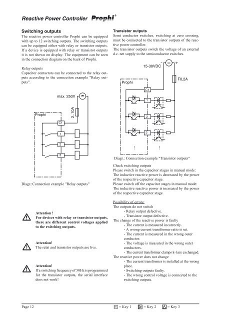
<strong>Reactive</strong> <strong>Power</strong> <strong>Controller</strong>Switching outputsThe reactive power controller Prophi can be equippedwith up to 12 switching outputs. The switching outputscan be equipped either with relay or transistor outputs.If a device is equipped with relay or transistor outputsit is not shown on display. The equipment can be seenin the connection diagram on the back of Prophi.Relay outputsCapacitor contactors can be connected to the relay outputsaccording to the connection example "Relay outputs".Transistor outputsSemi conductor switches, switching at zero crossing,must be connected to the transistor outputs of the reactivepower controller.The transistor outputs switch the voltage of an externald.c. net supply to the semiconductor switches.Prophi15-30VDCF0,2AC1max. 250V1ProphiC12..10A2132Diagr.:Connection example "Relay outputs"3Diagr.: Connection example "Transistor outputs"Check switching outputsPlease switch in the capacitor stages in manual mode:The inductive reactive power is decreased by the powerof the respective capacitor stage.Please switch off the capacitor stages in manual mode:The inductive reactive power is increased by the powerof the respective capacitor stage.TheAttention !For devices with relay or transistor outputs,there are different control voltages appliedto the switching outputs.Attention!relai and transistor outputs are live.Attention!If a switching frequency of 50Hz is programmedfor the transistor outputs, the serial interfacedoes not work!Possibility of errors:The outputs do not switch- Relay output defective.- Transistor output defective.The change of the reactive power is faulty- The current is measured incorrectly.- A wrong current transformer ratio is set.- The current is measured in the wrong outerconductor.- The voltage is measured in the wrong outerconductors.- The current transformer clamps k-l are exchanged.The reactive power does not change- The current transformer is installed at the wrongplace.- Switching outputs faulty.- The wrong control voltage is connected to theswitching outputs.Page 12= Key 1 = Key 2 = Key 3