Reactive Power Controller Operating instructions
Reactive Power Controller Operating instructions
Reactive Power Controller Operating instructions

Create successful ePaper yourself
Turn your PDF publications into a flip-book with our unique Google optimized e-Paper software.
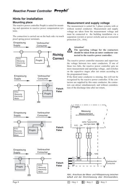
<strong>Reactive</strong> <strong>Power</strong> <strong>Controller</strong>Hints for installationMounting placeThe reactive power controller Prophi is suited for mountingand operation in reactive power compensation systems.The connection is carried out on the back side via touchproof spring power terminals.EinspeisungSupplyEVU-MessungElectricity-MeterEinspeisungSupplyEVU-MessungElectricity-MeterVerbraucherConsumerProphiVerbraucherConsumerProphiRichtigCorrectFalschFalseMeasurement and supply voltageThe measurement is suited for 3 phase systems with orwithout neutral conductor. Measurement and supplyvoltage are taken from the measurement voltage andmust be connected to the building installation via aseparation (switch or power switch) and an overcurrentprotection (2A...10A).Attention!The operating voltage for the contactorsshould be taken from an outer conductor connectedto the reactive power controller.The reactive power controller measures and supervisesthe voltage between two outer conductors. If one ofthose two fails, the reactive power controller gets nomore measurement and operating voltage, and switcheson the capacitive stages after net return according tothe programmed times.If the third outer conductor is missing, this will not berecognized by the reactive power controller. If the contactorsare supplied by this outer conductor, the contactorscan attract simultaneously and without considerationof the discharge time after net return.EinspeisungSupplyVerbraucherConsumerProphiMessungMeasurementEVU-MessungElectricity-MeterProphiFalschFalseL/Lsiehe Typenschildsee type label0,01 .. 5Ak l L2 L3EinspeisungSupplyProphiVerbraucherConsumerEVU-MessungElectricity-MeterFalschFalseL1L2L3PEkl../5(1)A2 .. 10AVerbraucherConsumerAbb.: Anschluss der Mess- und Hilfsspannung zwischenL2-L3 und der Strommessung über Stromwandlers.Page 8= Key 1 = Key 2 = Key 3