Piper Seneca PA-34 - Langley Flying School
Piper Seneca PA-34 - Langley Flying School
Piper Seneca PA-34 - Langley Flying School

Create successful ePaper yourself
Turn your PDF publications into a flip-book with our unique Google optimized e-Paper software.
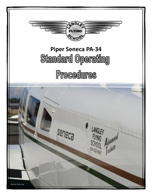
Photo by: Philip Craig<strong>Piper</strong> <strong>Seneca</strong> <strong>PA</strong>-<strong>34</strong>
<strong>PA</strong>-<strong>34</strong>-200TSTANDARD OPERATING PROCEDURES<strong>PA</strong>GE 2Dec 2008—This page has been intentionally left blank—
<strong>PA</strong>-<strong>34</strong>-200TSTANDARD OPERATING PROCEDURES<strong>PA</strong>GE 4Dec 2008Missed Approach................................................................................................................................ 42Stabilized Approach............................................................................................................................ 42Figure: Standard IFR Approach Profile ............................................................................................. 43Appendices............................................................................................................................................. 44Appendix: Standard Calls .................................................................................................................... 44Airspeed and Flap Changes.............................................................................................................. 44Altitude Clearances and Deviations ................................................................................................. 44Radio Navigation Settings................................................................................................................ 44Checklist Interruptions.................................................................................................................... 44Transfer of Controls ........................................................................................................................ 44ATC Communications...................................................................................................................... 44Autopilot Operations ...................................................................................................................... 44Appendix: Standard Approach Plate Briefing....................................................................................... 45Sample Approach Plate Briefing 1.................................................................................................... 45Sample Approach Plate Briefing 2.................................................................................................... 45
<strong>PA</strong>-<strong>34</strong>-200TSTANDARD OPERATING PROCEDURES<strong>PA</strong>GE 5Dec 2008Introduction to Standard Operating ProceduresBackgroundStandard Operating Procedures are just what the phrase says—they are standardized procedures used byall persons conducting flight operations. Quite simply, the rationale behind them is safety. If everyoneconducts himself or herself in a standardized, predictable fashion, then there are no surprises, there is noconfusion, and safety—in general—is enhanced as depicted in The Far Side (December 5, 2007) comicbelow:For those you who move on to multi-crewoperations, Standard Operating Procedures—orSOPs—will become a professional way of life. SOPshave been central feature of the <strong>Langley</strong> <strong>Flying</strong><strong>School</strong> Commercial Pilot Program, and it is logicaland appropriate to extend them into this program.For commercial students, then, the multi-engineSOPs will not feel that alien—there are only slightvariations that reflect the specific requirement ofadvance aircraft operations and procedures. ForPrivate Pilots enrolled in this program, however, thiswill likely be the first time they are exposed to theSOP patterns of flying—it may feel awkward at first,but with time they will quickly make sense and feelcomfortable.Our motivation for including SOPs in <strong>Langley</strong> <strong>Flying</strong><strong>School</strong>’s advanced training programs was a storyrelayed to us by a fresh commercial pilot who wasselected for right-seat training on a King Air. Thefellow was not successful for many reasons—theemployer provided piecemeal training, unfortunatelyowing to limited recourses, but the candidate wasparticularly hung-up with a new form of flying inwhich his tasks in the cockpit were limited to select actions and calls—SOPs. He had received inadequatetraining during his training at the flight-school level.SOPs are primarily made up of actions and cockpit calls made by crewmembers during flight, but SOPsalso extend into pre-flight activity. All training flights are preceded with a weather briefing and a weightand balance calculation at <strong>Langley</strong> <strong>Flying</strong> <strong>School</strong>. This in a very basic form is an example of an SOP.Perhaps the best description of SOPs is that they are a script that everyone in a company shares andpractice during every flight. As with any script, the content must be memorized.The PF, PNF, and PICNormally, SOPs establish complementary tasks for specific phases of a flight operation for two roles—the“pilot flying” (PF) and the “pilot not flying” (PNF). These tasks are associated with calls—e.g., “gear up”—made in this case by the PF—and actions—e.g., the PNF raises the gear and responds “gear in transit”.Normally the PF and PNF responsibilities are for the most part independent of who is PIC and who is SIC
<strong>PA</strong>-<strong>34</strong>-200TSTANDARD OPERATING PROCEDURES<strong>PA</strong>GE 9Dec 2008simply be rejected, the throttles reduced to idle, and the aircraft returned to the remaining runwaysurface.<strong>Langley</strong> Airport—or any short runway—is a different matter. When departing from <strong>Langley</strong> Airport, V 2 istypically not achieved until after the aircraft has left the airport perimeter and is crossing—or has justcrossed—the roadways that lie of the end of each departure. Obviously, the confined runway departurepresents the greater risks, and in an effort to manage the increased risks, the term decision speed is used.Decision Speed (V 1 )The formal definition of decision speed (V 1 ) is “the speed below which a pilot of a multi-engine aircraftwill reject a takeoff in the event of an engine failure, and above which the pilot will continue with thetakeoff using the remaining engine(s).” Theoretically, V 1 is the specified speed during a departure groundrunacceleration, above which, the aircraft has achieved sufficient velocity for the control surfaces tobecome effective in countering the adverse effects of an engine failure. If an engine failure occurs aboveV 1 , the crew continues the takeoff and deals with the failed engine in the air. Should an engine failureoccur below V 1 , the control surfaces are ineffective in countering adverse effects of an engine failure, andcrew must reject the takeoff and bring the aircraft to a stop on the remaining runway. For takeoffs incommuter and airline transport category aircraft, it is required that the distance required to accelerate toV 1 , and subsequently reject the takeoff and bring the aircraft to a stop 6 —referred to as Accelerate-stopDistance (ASD)—must always be less than the available distance on a runway—Accelerate-stop DistanceAvailable (ASDA). 7For transport category aircraft, V 1 calculations tables are published by the aircraftmanufacturer, which take into consideration takeoff data such as pressure altitude, temperature, weightand wind conditions—V 1 changes in accordance with variations in these conditions (as do V r and V 2 ). Forlight twin-engined aircraft like the <strong>Seneca</strong>, however, the publication of a decision speed is not required forcertification. Nevertheless, <strong>Piper</strong> publishes an Accelerate-stop Distance data based on the speed of 80MPH—that is, they provide data for the distance required to accelerate the aircraft to 80 MPH, and thenreject the takeoff and stop under various conditions of pressure altitude, temperature, weight, and wind(see p. 9-6 of the POH). While V 1 does not exist for the <strong>Seneca</strong>, the concept of a decision speed can beapplied, not only for training purposes, but also an effective tool in dealing with takeoff engine failuresduring confined runway departures.Let us now examine how decision speed will be incorporated into the Standard Operating Procedures.When departing from a confined runway such as is found at <strong>Langley</strong> Airport, the PF will brief 90 MPH as V 1decision speed. If the engine failure is below 90 MPH, an automatic rejection of the takeoff mustimmediately occur. Below 90 MPH we are too close to V mc to risk continuing in the air; the gear will stillbe down, and onset of drag from the failed engine—assuming the failure is 100%—will suddenly debilitatean effort to gain altitude and increase speed. It is better to take the fence right-side-up at the far end ofthe runway, rather risk the onset of V mc autorotation only feet above ground obstacles. Conversely, at 90MPH we are only 3 MPH from the single-engine best-angle climb (V xse ), if airspeed is immediatelypreserved with effective pitch control, and the failed engine managed rapidly and efficiently, the aircraftwill accelerate to the blue line and a safe single-engine climb established.6Specifically, instead of stopping the aircraft, certification actually requires only that the aircraft be slowed to less than 35knots.7Accelerate-stop Distance Available (ASDA) is defined as the length of the takeoff run available plus the length of any“stopway” where these exist at runway. The “stopway” is a rectangular area on the ground at the end of the runway, inthe direction of takeoff, which is prepared as a suitable area in which an aircraft can be stopped in the case of anabandoned takeoff, and is marked over the entire length with yellow chevrons (for discussions regarding stopways, seeAIP, AGA 3.6; for an example of published or “declared” distances, see the Aerodrome Chart for Nanaimo Airport in theIFR publication Canada Air Pilot, CAP 3—British Columbia).
<strong>PA</strong>-<strong>34</strong>-200TSTANDARD OPERATING PROCEDURES<strong>PA</strong>GE 10Dec 2008If the engine failure occurs above 90 MPH but below V 2 (blue line 105 MPH), speed must be conserved byimmediately pitching forward—essentially to redirect the thrust from the climb to maximumacceleration—and the actions required to identify and feather the offending engine must be accurate andspontaneous. For all of this to work, the right hand of the PF shall always be on the throttles and at theready during the First Segment Climb; additionally, the gear must be retracted without delay. Perhapsmore importantly, the health of the engines with respect to their ability to develop power must becarefully examined prior to beginning the First Segment Climb, and, therefore, proper and effectivemonitoring of aircraft and engine performance during the pre-rotation phase of the takeoff is critical. Letus now examine in greater detail how an engine failure during a confined-runway departure will bemanaged.Second Segment Climb (V 2 )Second Segment climb performance—which is composed of maximum power and blue line airspeed—continues through to an altitude at which obstacle and terrain clearance is no longer a factor—in all cases,not below 400’ AAE. During the Second Segment climb, no power changes should be made. Once theaircraft is safely clear of obstacles and terrain—again, not less than 400’ AAE—the Second Segment Climbis completed.Third Segment Climb (V 3 En route Climb)To transition to a Third Segment climb, the throttles are retarded to 25”MP and RPM set to 2500. Pitch isdecreased—normally from about 10° to 5°—and speed is accelerated to 120 MPH.Departure Engine FailureIn a departure engine failure, time is of the essence. The PF must be quick and efficient here, and must beabsolutely accurate in his or her response. The departure engine failure is the point of greatest risk, andthroughout the response to this emergency, the PF must be prepared to pull the power back and treat thetwin as if it were a single-engine aircraft with a failed engine. When does the PF retard the throttles toidle and settle the aircraft in a field? The answer is simple: whenever the airspeed deteriorates andapproaches the V mc red line. When this happens, the game is over and the throttles closed. Of course, themain strategy of the PF is not to get in this position in the first place.Here, then, is the vital-actions response of the pilot to an engine failure on departure:In the event of an engine failure below V 1 :Throttle.....................................................IdleAircraft................Land or Stop Straight AheadControl Column.................................Full BackBrakes.............................................MaximumIn the event of an engine failure above V 1 :Control....................................Direction & V mcPower..............................................MaximumDrag ................................ Retract gear & flapsIdentify ......................Dead foot, dead engineVerify .............................. Confirm with powerFeather........................................Dead engineFire Check.......................... Check dead engineEmergency Destination ......................... SelectATC ...................................Declare Emergency
<strong>PA</strong>-<strong>34</strong>-200TSTANDARD OPERATING PROCEDURES<strong>PA</strong>GE 11Dec 2008Control is crucial in an engine failure during departure! Remember, right after rotation is the dangerzone, and it does not end until the blue is maintained and the engine is feathered. So the “control”element which immediately follows an engine failure on departure is pivotal. First, you must be preparedto immediately but smoothly pitch forward—if this is not done, the airspeed will bleed within secondsafter the engine quits. How far? Well, until we have the engine feathered, we should target pitchingforward until the climb stops and the aircraft is simply maintaining its altitude. Obviously, terrain andobstacles are determining factors, and if terrain is confining, a safe-speed pitch-up attitude may betargeted—but only provided there is no deterioration in the airspeed condition. Avoid too rapidlypitching forward to the point that the aircraft starts to descend, as obviously we must work with thescenario that there is precious little airspace between the aircraft and the ground.Equally important, you must carefully monitor your airspeed—if there is ever a time to monitor yourairspeed with extreme accuracy, this is it! The parameters are quite simple here—if the airspeedeventually bleeds and migrates to the red-line V mc , you have no choice but to power back and treat thetwin like a single engine aircraft—make gentle turns to avoid fixed objects as you let the aircraft settle onto the ground. 8As long as the power is off the maximum setting, the V mc “flip” must occur somewherebelow red line speed—the problem is that you cannot predict exactly where this is, given the variables ofaltitude and aircraft weight.A third reaction of the pilot which must be considered is keeping the aircraft tracking straight—by keepingstraight you will make it far more likely to correctly identify the bad engine in the minimum number ofseconds—and remember the seconds count is crucial here. The governing factor is simply this: if youmake an effort to keep the track straight during the failure, your feet will be in the best position to helpyou identify the “dead foot.” If, for example you relinquish all rudder pressure and attempt to controlwith simple aileron input, things will make far less sense.There is the chance that the engine failure might be associated with a fire. To guard against the wingmelting off, ensure you visually check the nacelle of the bad engine for pealing or discoloured paint,smoke or flames after the engine has been feathered. In the case of an engine fire, the solution is simple:cut-off the source as per the POH.Ideally advise ATC as soon as practical once you have control of your aircraft and the failed engine hasbeen feathered. ATC can clear all conflicting traffic, and assist in tracking, and even altitude monitoring.You will have to decide if you will return to <strong>Langley</strong> Airport, if this is you departure point, or head for avicinity airport with a longer runway and possibly emergency-response services.8Obviously, the fuel and electrical systems must be safely shut down—the “engine fire” drill, applied to both engines willeffectively do this, and then the master switch and magnetos should be selected off.
<strong>PA</strong>-<strong>34</strong>-200TSTANDARD OPERATING PROCEDURES<strong>PA</strong>GE 12Dec 2008—This page has been intentionally left blank—
<strong>PA</strong>-<strong>34</strong>-200TSTANDARD OPERATING PROCEDURES<strong>PA</strong>GE 13PREFLIGHT Dec 2008Standard Operating ProceduresThe PF shall arrive at the airport to allow for sufficient time to complete the pre-flight, cockpit checks,workaround, a crew pre-flight briefing and any other duties that must be preformed. Typically, this willbe between 30 minutes and one hour before a booking time.Pre-flightActionFlight Planning.........................................CompeteMaintenance Status..................................... CheckIn addition to flight preparation activity requiredby the Canadian Aviation Regulations, the PF shallcalculate the following:Weight and Balance...........................Within limitsTakeoff Distance................................... CalculatedLanding Distance................................... CalculatedASD................................................Less than ASDASOP CallCockpit ChecksActionFire Extinguisher .............................. Check/SecureFirst-aid Kit .................................................. CheckLife Jackets (if required)............................... CheckFlight Supplement........................................ CheckJourney Log....................Review for AirworthinessPilot Operating Handbook ........................... CheckOxygen Masks (if required).......................... CheckAll Electric Switches ..........................................OffControl Locks ..........................................RemovedSeat Belts not in Use................................. SecuredCircuit Breakers.....................................Checked InAvionics Master ................................................OffLanding Gear Control ................................... DownMaster.............................................................. OnLanding Gear Indictors.............................. 3 GreenFuel Gauges ................................................. CheckThrottles..................................................... ClosedMixtures .............................................. Idle Cut-offFuel Pumps (Individually).. On, pressure check, OffPitot Heat ......................................................... OnLanding, Navigation, Anti-Collision Lights ........ OnStall Indicator....................... Check Horn and LightSOP Call
<strong>PA</strong>-<strong>34</strong>-200TSTANDARD OPERATING PROCEDURES<strong>PA</strong>GE 14PREFLIGHT Dec 2008ActionPitot Mast............................................ Check HeatPitot Heat .........................................................OffLanding, Navigation, Anti-Collision Lights ........OffMaster..............................................................OffSOP CallWalk-AroundActionPerform exterior inspection as per the POH 7-2:1. Fuel Drains (8): two fuel tank drains on eachwing, a gascolator drain near the bottom ofeach nacelle, and two crossfeed drains on thebottom of the fuselage (use Tupperwarecontain found in nose baggage compartmentto catch the fuel. Sump is drain by leversfound behind the front passenger seat.)2. Right wing, aileron and flap—no damage, noice. Check hinges.3. Right main gear—no leaks, tires inflated andnot excessively worn, 3 ½ inches pistonexposed under static load.4. Right wing tip—no damage.5. Right leading edge—no damage or ice.6. Fuel cap—open to check quantity and color offuel. Check cap vent, and then secure.7. Right engine nacelle—open doors to inspectengine. Check oil quantity—six to eightquarts; add oil when oil reaches six quarts orbelow. Secure both inspection doors.8. Right propeller—no nicks or leaks, spinnersecure and not cracked.9. Nose section—undamaged.10. Cowl flaps—open and secure.11. Nose section—undamagedSOP Call
<strong>PA</strong>-<strong>34</strong>-200TSTANDARD OPERATING PROCEDURES<strong>PA</strong>GE 15PREFLIGHT Dec 2008ActionSOP Call12. Nose gear—no leaks, tire inflated and notexcessively worn, 2 ½ inches piston exposedunder static load, tow bar removed, conditionof landing light checked.13. Forward baggage door—secure and locked.14. Windshield—clean and secure.15. Left wing, engine nacelle and landing gear—inspect as completed on the right side.16.17. Pitot tube—hole unobstructed, heat checkedby feel if need is anticipated.18. Stall warning vanes—no damage, freemovement.19. Rear door—latched.20. Left static vent—unobstructed.21. Dorsal fin air scoop—free of obstruction22. Empennage—no damage, free of ice, hingessecure.23. Right static vent—unobstructed.24. Antennas—secure and undamaged.
<strong>PA</strong>-<strong>34</strong>-200TSTANDARD OPERATING PROCEDURES<strong>PA</strong>GE 16PREFLIGHT Dec 2008Figure: Walk-Around Chart
<strong>PA</strong>-<strong>34</strong>-200TSTANDARD OPERATING PROCEDURES<strong>PA</strong>GE 17PREFLIGHT Dec 2008Fuel Requirements & ProceduresActionThe minimum fuel requirement for VFR flight is toarrive at the destination with a reserve of 1 hour offuel at normal cruise power settings.SOP CallThe minimum fuel requirement for IFR flight is tobe able fuel to fly to the destination, fly anapproach & missed approach, the procedure to asuitable alternate and conduct an approach, thenenough fuel to be able to fly for a further 45minutes at normal cruise power settings, plus anycontingency fuel required.Refueling the aircraft with passengers on board isprohibited.Ramp & Gate ProceduresActionThe PF is responsible for the safety and security ofpassengers during movement from the passengerlounge to the aircraft.SOP CallFinal Aircraft InspectionActionRear Baggage Door ..................................... SecureRear Passenger Door................................... SecureLeft Engine Cowling..................................... SecureWheel Chocks .........................................RemovedFront Baggage Door .................................... SecureRight Engine Cowling .................................. SecureSOP Call
<strong>PA</strong>-<strong>34</strong>-200TSTANDARD OPERATING PROCEDURES<strong>PA</strong>GE 18PREFLIGHT Dec 2008Passenger BriefingActionThe PF must ensure that all passengers areprovided with a safety briefing that includes thefollowing information:1. Where, when, and how carry-on baggageis required to be stowed;2. the fastening, unfastening, andadjustment of safety belts and theirrequirement for use during flight;3. when the seat backs must be securedupright and tables stowed;4. the location of emergency exits (includinginstructions to persons sitting next to anexit on how the exit operations);5. location, purpose, and advisability ofreading safety feature cards;6. the regulatory requirement to obey crewinstructions regarding seat belts and nosmoking (or the location of fasten seatbelts and no smoking signs);7. the location of emergency equipmentsuch as ELT, fire extinguisher, survivalequipment, first aid kit and life raft;8. the use of passenger-operated portableelectronics, the location of fixedpassenger-oxygen systems, including thelocation and presentation of masks,activation of the flow of oxygen, andinstruction on how to correctly don andsecure the mask (this must include ademonstration) and the priority forpersons assisting others;9. the location and use of life preservers(demonstration required) and instructionon how and when to inflate lifepreservers.SOP Call
<strong>PA</strong>-<strong>34</strong>-200TSTANDARD OPERATING PROCEDURES<strong>PA</strong>GE 19PRE-START Dec 2008Pre-StartActionMaster.............................................................. OnAvionics Master ................................................ OnTransponder .............................................StandbyTransponder Code.............................................SetHSI Slaving ...................................................... TestATIS ............................................................RecordAltimeters ........................................................SetClearance Delivery (if applicable)...............ContactMarker Beacon Lights .................................. CheckGPS ................................................... Check & TestGPS Flight Plan (FPL) .........................................SetNav/Com #1...........................................Test & SetADF....................................... Test, Set, and SlavedNav/Com #2...........................................Test & SetAvionics Master ................................................OffMaster..............................................................OffTakeoff and Departure Procedures............... Brief 9SOP CallRunway ........................................................“___”Crosswind.....................................................“___”Takeoff Procedure: V r , V 2 , V 3 .........................“___”Departure Procedures ................................ “___” 10Communications Failure ................Brief VMC/IMCEngine Failure Procedures.............................. Brief In the event of an engine failure below V 1 :Throttle..................................................... IdleAircraft ...............Land or Stop Straight AheadControl Column.................................Full BackBrakes.............................................MaximumIn the event of an engine failure above V 1 :Control....................................Direction & V mcPower .............................................MaximumDrag.................................Retract gear & flapsIdentify ...................... Dead foot, dead engineVerify.............................. Confirm with powerFeather ....................................... Dead engineFire Check ......................... Check dead engineEmergency Destination......................... SelectATC ...................................Declare Emergency9The PF shall conduct a Takeoff Briefing (TOB) prior to every departure. At the discretion of the PF, the TOB may beconducted just prior to boarding, prior to engine start-up, or during taxi, but it must be conducted prior to the request fortakeoff clearance.10Reference to a “standard” departure implies the Standard Departure Profile outline in the Appendix.
<strong>PA</strong>-<strong>34</strong>-200TSTANDARD OPERATING PROCEDURES<strong>PA</strong>GE 20PRE-START Dec 2008ActionForward Baggage Door ............................... SecureOxygen.................................................... On or OffPassengers..................................................... BriefBrake Handle .................................................... OnCowl Flaps..................................................... OpenFuel Selectors....................LEFT X-feed—RIGHT OnSOP Call
<strong>PA</strong>-<strong>34</strong>-200TSTANDARD OPERATING PROCEDURES<strong>PA</strong>GE 21ENGINE STARTS Dec 2008Engine StartsCold Engine StartActionHobbs & Time..............................................RecordBrake Handle .................................................... OnBoth engines:Mixtures .............................................. Idle Cut-offMaster.............................................................. OnThrottles..................................................... ClosedPropellers .................................................ForwardMagnetos.......................................................... OnAlternators ....................................................... OnLeft Engine ONLYFuel Pump ........................................................ OnMixture..................................................... Set RichThrottle.............................................Advance 75%Fuel Flow ..........................Stabilized for 3 SecondsThrottle....................................................... ClosedMixture....................................................... ClosedPropeller........................................................ClearStarter .................................................Engage LeftAs engine starts:Mixture.............................Advance at engine startAfter engine starts:Oil Pressure.....................................Above red lineThrottle....................................................800 RPMFuel Pump.........................................................OffFuel Pressure ............................................... CheckReview & confirm actions of AFTER ENGINE STARTCHECKLIST are completeRight Engine ONLYFuel Pump ........................................................ OnMixture..................................................... Set RichThrottle.............................................Advance 75%Fuel Flow ..........................Stabilized for 3 SecondsThrottle....................................................... ClosedMixture....................................................... ClosedPropeller........................................................ClearSOP CallCall for COLD ENGINE START CHECKLISTCall CLEAR FOR ENGINE STARTS out pilot stormwindowState: STARTING LEFT ENGINECall for AFTER ENGINE START CHECKLISTCall AFTER ENGINE START CHECKLIST COMPLETE
<strong>PA</strong>-<strong>34</strong>-200TSTANDARD OPERATING PROCEDURES<strong>PA</strong>GE 22ENGINE STARTS Dec 2008ActionStarter .............................................. Engage RightAs engine starts:Mixture.............................Advance at engine startAfter engine starts:Oil Pressure.....................................Above red lineThrottle....................................................800 RPMFuel Pump.........................................................OffFuel Pressure ............................................... CheckReview & confirm actions of AFTER ENGINE STARTCHECKLIST are completeSOP CallState: STARTING RIGHT ENGINECall for AFTER ENGINE START CHECKLISTCall AFTER ENGINE START CHECKLIST COMPLETECall COLD ENGINE START CHECKLIST COMPLETEHot Engine StartActionBrake Handle .................................................... OnBoth EnginesMixtures ............................................. Idle Cut-offMaster.............................................................. OnThrottles.................................................. ¼“ OpenPropellers .................................................ForwardMagnetos.......................................................... OnAlternators ....................................................... OnStarter .................................................Engage LeftAs engine starts:Mixture.............................Advance at engine startAfter engine starts:Oil Pressure.....................................Above red lineThrottle....................................................800 RPMFuel Pump.........................................................OffFuel Pressure ............................................... CheckSOP CallCall for HOT ENGINE START CHECKLISTCall CLEAR FOR ENGINE STARTS out pilot stormwindowState: STARTING LEFT ENGINECall for AFTER ENGINE START CHECKLIST
<strong>PA</strong>-<strong>34</strong>-200TSTANDARD OPERATING PROCEDURES<strong>PA</strong>GE 23ENGINE STARTS Dec 2008ActionReview & confirm actions of AFTER ENGINE STARTCHECKLIST are completeStarter .............................................. Engage RightAs engine starts:Mixture.............................Advance at engine startAfter engine starts:Oil Pressure.....................................Above red lineThrottle....................................................800 RPMFuel Pump.........................................................OffFuel Pressure ............................................... CheckReview & confirm actions of AFTER ENGINE STARTCHECKLIST are completeSOP CallCall AFTER ENGINE START CHECKLIST COMPLETEState: STARTING RIGHT ENGINECall for AFTER ENGINE START CHECKLISTCall AFTER ENGINE START CHECKLIST COMPLETECall HOT ENGINE START CHECKLIST COMPLETEFlooded Engine StartActionBrake Handle .................................................... OnBoth EnginesFuel Pumps .......................................................OffMixtures .............................................. Idle Cut-offPropellers .................................................ForwardMaster.............................................................. OnMagnetos.......................................................... OnAlternators ....................................................... OnSOP CallCall for FLOODED ENGINE START CHECKLISTCall CLEAR FOR ENGINE STARTS out pilot stormwindowState: STARTING LEFT ENGINELeft Engine ONLYThrottle...................................................Full OpenPropeller........................................................ClearStarter .................................................Engage LeftAs engine starts:Throttle...........................................Retard RapidlyMixture......................................... Advance Slowly
<strong>PA</strong>-<strong>34</strong>-200TSTANDARD OPERATING PROCEDURES<strong>PA</strong>GE 24ENGINE STARTS Dec 2008ActionAfter engine starts:Oil Pressure.................................................. CheckThrottle....................................................800 RPMFuel Pressure ............................................... CheckReview & confirm actions of AFTER ENGINE STARTCHECKLIST are completeRight Engine ONLYThrottle...................................................Full OpenPropeller........................................................ClearStarter .............................................. Engage RightAs engine starts:Throttle...........................................Retard RapidlyMixture......................................... Advance SlowlyAfter engine starts:Oil Pressure.................................................. CheckThrottle....................................................800 RPMFuel Pressure ............................................... CheckReview & confirm actions of AFTER ENGINE STARTCHECKLIST are completeSOP CallCall for AFTER ENGINE START CHECKLISTCall AFTER ENGINE START CHECKLIST COMPLETEState: STARTING RIGHT ENGINECall for AFTER ENGINE START CHECKLISTCall AFTER ENGINE START CHECKLIST COMPLETECall HOT ENGINE START CHECKLIST COMPLETE
<strong>PA</strong>-<strong>34</strong>-200TSTANDARD OPERATING PROCEDURES<strong>PA</strong>GE 25TAXI & PRE-TAKEOFF Dec 2008TaxiActionAvionics Master ................................................ OnFuel Selectors....................RIGHT X-feed—LEFT OnTaxi Clearance............................Obtain if requiredWing Clearance............................................ CheckSOP CallCall LEFT WING CLEAR, RIGHT WING CLEARBrakes..........................................Release & CheckInstruments ................................................. CheckAs turn coordinator responds in a turn callRIGHT/LEFT WING DOWN, BALL LEFT/RIGHT. Ifthe attitude indicator stay steady in a turn callSTEADY. Confirm that the compass is free bystating COM<strong>PA</strong>SS FREE AND FLOATING.Pre-TakeoffActionSOP CallCall for RUNUP CHECKLISTThrottles................................................1000 RPMPropeller Blast Area............................ Check ClearPropeller Blades...............Clear of Water or DebrisBrakes...............................................................SetGPS ........................................................ Set NAV 4GPS ................................... Set Moving Map RangeGPS ..........................Set/confirm Active WaypointGPS .......................................Set OBS or LEG modeGPS ..................... Altimeter and Altitude (ALT) SetGPS ..........................Load Approach (if applicable)GPS ...............................................RAIM ApproachGPS ........................................................ Set NAV 4
<strong>PA</strong>-<strong>34</strong>-200TSTANDARD OPERATING PROCEDURES<strong>PA</strong>GE 26TAXI & PRE-TAKEOFF Dec 2008ActionTrim .................................................................SetElectric Trim.................................................... TestVacuum......................................... Check 5”Hg ±1”Landing and Navigation Lights .......................... OnAlternators .................................................. CheckLanding and Navigation Lights ..........................OffPitot Heat ....................................Check load drawFuel Sectors ................................RIGHT & LEFT OnMixtures ...................................................Full RichThrottles................................................2000 RPMMagnetos...................................................Check 11Oil Temperatures and Pressures .................. CheckPropellers (Individually)......... 3 Cycles of 300 RPMPropellers ............................. Reduce to 1900 RPMThrottles .........................................Increase 1”HgRPMs ...................................................Check 1900Throttles........................................Decrease 1”Hg;Propellers .......................................Set 2000 RPM.Mixtures ..............................................Check FlowThrottles...........................................Set 1500RPMPropellers (Individually)................Feather Check 12Throttles....................................................... CloseOil Pressure.................................................. CheckThrottles................................................1000 RPMSOP CallCall RUNUP CHECKLIST COMPLETE11Maximum Drop 175 RPM; maximum difference 50 RPM.12RPM must drop to 1000 RPM in 1 to 3 seconds—slower feathering indicates inadequate dome pressure.
<strong>PA</strong>-<strong>34</strong>-200TSTANDARD OPERATING PROCEDURES<strong>PA</strong>GE 27TAXI & PRE-TAKEOFF Dec 2008ActionMagnetos....................................................... BothAuto Pilot.....................................................All OffFuel Supply .............................................SufficientEngine Gauges ............................................. CheckFlight Instrument .........................Set and CheckedFuel Selectors.................................................... OnTurbochargers...................................................OffMixtures ...................................................Full RichPropellers .......................................... Full ForwardHarness/Hatches/Seat ............... Check and SecureControl Column............................Free and CorrectTime............................................................RecordSOP CallCall for PRE-TAKEOFF CHECKLISTCall PRE-TAKEOFF CHECKLIST COMPLETERunwayActionObtain takeoff clearance with a short delay 13 .Anti-collision Lights...........................................ONPitot Heat (IFR) .................................................ONFuel Pumps .......................................................ONTransponder .............................................. Set ALTSOP CallPrior to entering or crossing a runway, in additionto obtain required clearances visually clear andcall CLEAR LEFT, CLEAR RIGHTCall for RUNWAY CHECKLISTCall RUNWAY CHECKLIST COMPLETEIn position, check HSI Heading Bug aligned withRunway Heading.When “Cleared for Takeoff,” turn the landing andtaxi lights ON.13The delay is required owing to the short length of the runway and the limited opportunity to properly check engineperformance prior to takeoff.
<strong>PA</strong>-<strong>34</strong>-200TSTANDARD OPERATING PROCEDURES<strong>PA</strong>GE 28TAKEOFF & DE<strong>PA</strong>RTURE Dec 2008Normal TakeoffActionSOP CallCall for TAKEOFF CHECKLISTLanding Lights...................................................ONPower ..............................................Set 2000 RPMEngine Gauges ................................Confirm Green Call LEFT ENGINE GREEN, RIGHT ENGINE GREENCall MAXIMUM POWERBrakes........................................................ReleaseThrottles...............................Set Maximum PowerPower Gauges.....................................Check Equal Call NO SPLIT NEEDLESASI ............................ Confirm Increasing Airspeed Call AIRSPEED ALIVEASI ............................................................ 80 MPH At V r call ROTATIONVSI .......................................Confirm Positive Rate Call POSITIVE RATE, GEAR UPGear.................................................................. U<strong>PA</strong>SI .......................................................... 105 MPH Call V 2At 400’ AAE:ASI ................................................Accelerate to V 3Manifold Pressure...................................... Set 25”RPM.................................................Set 2500 RPMFlaps .......................................................... RetractCall 105 FOR 120, CLIMB POWER SETFigure: Standard Departure Profile
<strong>PA</strong>-<strong>34</strong>-200TSTANDARD OPERATING PROCEDURES<strong>PA</strong>GE 29TAKEOFF & DE<strong>PA</strong>RTURE Dec 2008Obstacle TakeoffActionLanding Lights...................................................ONPower ..............................................Set 2000 RPMEngine Gauges ................................Confirm GreenThrottles...............................Set Maximum PowerPower Gauges.....................................Check EqualBrakes........................................................ReleaseASI ............................ Confirm Increasing AirspeedASI ............................................................ 70 MPHSOP CallCall for TAKEOFF CHECKLISTCall LEFT ENGINE GREEN, RIGHT ENGINE GREENCall MAXIMUM POWERCall NO SPLIT NEEDLESCall AIRSPEED ALIVEAt V r call ROTATIONVSI .......................................Confirm Positive Rate Call POSITIVE RATE, GEAR UPGear.................................................................. U<strong>PA</strong>SI ............................................................ 80 MPH Call V 2Clear of obstacles:Flaps .............................................................Set 0° Call FLAPS 0ASI .....................................Accelerate to 105 MPH Call V 3At 400’ AAE:ASI ........................................ Accelerate to V 3 + 15Manifold Pressure...................................... Set 25”RPM.................................................Set 2500 RPMFlaps .........................................Confirm RetractedCall 105 FOR 120, CLIMB POWER SETFigure: Obstacle Departure Profile
<strong>PA</strong>-<strong>34</strong>-200TSTANDARD OPERATING PROCEDURES<strong>PA</strong>GE 30TAKEOFF & DE<strong>PA</strong>RTURE Dec 2008ClimbActionPerform AFTER TAKEOFF CHECKLIST passingthrough 1000’ AAE:Landing Lights..................................................OFFFuel Pumps ...................................OFF IndividuallyEngine Gauges ................................Confirm GreenSOP CallCall AFTER TAKEOFF CHECKLIST COMPLETECall 500’ TO GO when approaching cruisingaltitude
<strong>PA</strong>-<strong>34</strong>-200TSTANDARD OPERATING PROCEDURES<strong>PA</strong>GE 31DESCENT Dec 2008CruiseActionPerform LEVEL/CRUISE CHECKLIST once level:Throttles...........................................................SetPropellers .........................................................SetMixture ............................................................SetCowl Flaps..................................................... CloseEGT .............................................................. CheckMixtures ...................................Adjust as requiredSOP CallCall LEVEL/CRUISE CHECKLIST COMPLETEDescentActionObtain ATISConduct clearing turnsStart descentMaintain the following proximity speeds:Within 3nm of aerodrome ...................120 MPHDownwind Leg.................. 115 MPH & 10° FlapsBase Leg ........................... 110 MPH & 25° FlapsFinal Approach.................... 90 MPH & 40° FlapsSeat backs......................................................ErectSeat belts.................................................... SecureFuel Selectors.................................................... OnLanding Light..................................................... OnFuel Pumps ....................................................... OnAuto Pilot..........................................................OffBrakes...................................................... CheckedApproach .................................................Briefed 14SOP CallPrior to descent below 1000’ AAE, call for PRE-LANDING CHECKLISTWind Conditions......................... Anticipated/ATISV ref ............................................................ 90 MPHFlap Configuration .................................... Flaps 40Call PRE-LANDING CHECKLIST COMPLETE14The approach briefing will give specific reference to anticipated wind conditions, V ref, and flap configuration.
<strong>PA</strong>-<strong>34</strong>-200TSTANDARD OPERATING PROCEDURES<strong>PA</strong>GE 32APPROACH & LANDING Dec 2008Final Approach & LandingActionBelow 1000’ AAE during an approach or departurethe cockpit will be STERILE. Conversations andactions among crew will only pertain to the landingactions and sequences.Prior to descent below 500’ AAE complete GUMPCHECKS:Gas........................... Fuel pumps and Selectors OnUndercarriage..............3 Green, One in the MirrorMixtures ............................................ Full ForwardPropellers .......................................... Full ForwardPrior to descending below 400’ AAE during a finallanding approach, the following conditions for astabilized approach must be established andmaintained:1. the airspeed is constant at V ref in the finallanding flap configuration;2. the glideslope is normal and steady;3. the runway centerline is accurately tracked.If the above conditions are not established, the PFshall conduct a missed approach.After touchdown:Flaps ..................................Immediately RetractedBrakes.......................................Maximum BrakingSOP CallCall GUMP CHECKS COMPLETE
<strong>PA</strong>-<strong>34</strong>-200TSTANDARD OPERATING PROCEDURES<strong>PA</strong>GE 33APPROACH & LANDING Dec 2008Figure: Standard Visual Approach Profile
<strong>PA</strong>-<strong>34</strong>-200TSTANDARD OPERATING PROCEDURES<strong>PA</strong>GE <strong>34</strong>MISSED APPROACH Dec 2008Missed ApproachActionPower ..............................................Set MaximumCall MISSED APPROACHCall MAX POWER SETSOP CallVSI .......................................Confirm Positive Rate Call POSITIVE RATE, GEAR UPGear.................................................................. U<strong>PA</strong>SI ..................................................................... V 2 Call V 2At 400’ AAE:ASI ................................................Accelerate to V 3Manifold Pressure...................................... Set 25”RPM.................................................Set 2500 RPMFlaps .......................................................... RetractCall 105 for 120, CLIMB POWER SETStabilized ApproachActionDuring the Final Approach and Landing phase, astabilized approach is to be flown. The aircraftmust be stabilized by 500’ AAE in VMC and 1000’AAE in IMC. Criteria for a stabilized approach is asfollows:1. The aircraft is in the landing configuration2. The aircraft is established on theapproach profile3. Indicated airspeed is within +10 KTS to –5KTS of target airspeed4. Power is managed to maintain the targetairspeedIn the event that this is not achieved, the PIC shallconduct a missed approach.SOP CallCall DESTABILIZED APPROACH, GOING-AROUND
<strong>PA</strong>-<strong>34</strong>-200TSTANDARD OPERATING PROCEDURES<strong>PA</strong>GE 35NON-NORMAL Dec 2008Non-Normal Standard Operating ProceduresGeneralThere are a host of emergencies that can potentially surface during the course of a flight. The key to anyemergency is the age old saying: aviate, navigate, communicate. It is imperative that control of theaircraft is established and maintained prior to any efforts to identify the problem. Obliviously, there aresituations where control and problem identification are essentially simultaneous.Rejected TakeoffActionThrottles..................................................... ClosedFlaps .......................................................... RetractBrakes........................Apply for Maximum BrakingCommunication ................................... Advice ATCSOP CallWhen an unsafe or non-normal situation requiringa rejected takeoff is identified by a member of thecrew, the PIC shall call REJECT, REJECTDo not identify problem to ATC at this timeMaintain constant brake pressure, avoidingskidding, until aircraft stops. An illusion can occurunder heavy braking such that the aircraft appearsto be stopping quicker than it actually is, causingthe brakes to be released prematurely.ONCE AIRCRAFT IS STOPPEDEvaluate situation using all resources available—i.e., ATC, cockpit indications, AFF, visualinspection—prior to initiating passengerevacuation. Remain on active runway to allow AFFfull access to aircraft.Determine if taxiing off the runway or a shut-downis required.Notify ATC of problem and intentions.
<strong>PA</strong>-<strong>34</strong>-200TSTANDARD OPERATING PROCEDURES<strong>PA</strong>GE 36NON-NORMAL Dec 2008Engine FailureThis condition is recognized by a loss of all thrust from an engine, as indicated by the engine gauges,asymmetric thrust, and/or airframe vibrations with abnormal or normal engine gauges. Whenconditions permit, conduct an evaluation of causes prior to feathering. It is recommended that thecauses not be investigated, and the propeller immediately feathered when the aircraft is less that 1000’AGL or climb performance is required. See the ENGINE FAILURE FLOW CHART for more detail.ActionControl............................ Rudder, Ailerons & PitchSOP CallMixtures ...................................................Full RichPropellers .......................................... Full ForwardThrottles..............................................Max PowerFlaps .......................................................... RetractGear........................................................... RetractIdentify Dead Engine.......................... “Dead Foot”Verify Dead Engine ..........................Close ThrottleFire Check .......................................... Dead EngineIf a fire exists, proceed immediately to ENGINEFIRE drill and SOPs.If a fire does not exist, continue with this SOP.If time permits: Fuel, Spark Air.Fuel Pump.................................................... OnFuel Selector ..................................... CrossfeedMagnetos................................................ CheckAlternate Air ........................................... SelectAlternate Heat ........................................ SelectIf still not rectified:Dead Engine Propeller...........................FeatherSpeed.................Maintain Blue Line (105 MPH)Operating EngineThrottle ............................... Set as requiredPropeller.............................. Set as requiredMixture................................ Set as requiredOil Temperature ................................ CheckCowl Flaps ........................... Set as requiredFeathered EngineMagnetos ...............................................OffFuel Pump ..............................................OffAlternator ..............................................OffFuel Selector...........................................OffAlternator Load............................................ CheckElectrical Load.........................Reduce as RequiredCall MAX POWERCall FLAPS UPCall GEAR UPCall FUELCall S<strong>PA</strong>RKCall AIRCall FEATHERING LEFT/RIGHT ENGINE
<strong>PA</strong>-<strong>34</strong>-200TSTANDARD OPERATING PROCEDURES<strong>PA</strong>GE 37NON-NORMAL Dec 2008Figure: Engine Failure Flow Chart
<strong>PA</strong>-<strong>34</strong>-200TSTANDARD OPERATING PROCEDURES<strong>PA</strong>GE 38NON-NORMAL Dec 2008Engine FireActionFuel selector .....................................................OffThrottle......................................................... ClosePropeller....................................................FeatherMixture.................................................Idle cut-offFirewall.....................................................Closed 15SOP CallCall FIRE LEFT/RIGHT ENGINECall FEATHERING LEFT/RIGHT ENGINEControl............................ Rudder, Ailerons & PitchOn operating engine:Mixtures...........................................Full RichPropellers .................................. Full ForwardThrottles......................................Max PowerFlaps .......................................................... RetractGear........................................................... RetractSpeed......................Maintain Blue Line (105 MPH)Operating EngineThrottle ............................... Set as requiredPropeller.............................. Set as requiredMixture................................ Set as requiredOil Temperature ................................ CheckCowl Flaps ........................... Set as requiredFeathered EngineMagnetos ...............................................OffFuel Pump ..............................................OffAlternator ..............................................OffFuel Selector...........................................OffAlternator Load............................................ CheckElectrical Load.........................Reduce as RequiredCall MAX POWERCall FLAPS UPCall GEAR UP15Heater/defroster off.
<strong>PA</strong>-<strong>34</strong>-200TSTANDARD OPERATING PROCEDURES<strong>PA</strong>GE 39NON-NORMAL Dec 2008Passenger EvacuationActionParking Brake.................................................... OnThrottles....................................................... CloseMixtures .............................................. Idle Cut-offMagnetos..........................................................OffMaster..............................................................OffSOP CallCall <strong>PA</strong>SSENGER EVACUATIONCall ENGINE SHUTDOWNCall EVACUATE, EVACUATEFire Extinguisher .........................................ObtainPassengers..............................Assist in Evacuation
<strong>PA</strong>-<strong>34</strong>-200TSTANDARD OPERATING PROCEDURES<strong>PA</strong>GE 40IFR Dec 2008IFR Standard Operating ProceduresHoldActionNav Aid .............................Tune, Identify, Test, SetSOP CallUpon reaching the Nav Aid:Time............................................................... StartTurn .............................. Entry Heading as per PODThrottle.............................................................SetTalk..........................Advice ATC Entering the HoldILS ApproachThe following SOP revolves around an ILS approach. However, the flow, format and standard calls canbe applied to other precision and non-precision approaches. It is also important to note that whenbelow 1000’ AAE during an approach or departure, conversation and actions among crew will onlypertain to the landing actions and sequences.ActionSOP CallSpeedFlaps ......................................................Set 10°Throttles ........................................ Set 16” MPNav Aids............................Tune, Identify, Test, SetHSI ....................................Confirm GPS or NAVATIS........................................................ObtainApproach ........................................................Brief Approach and runway number.....................“___”Airport name ................................................“___”Chart page number.......................................“___”Chart date/effective date .............................“___”Final approach course, Freq & Ident .............“___”Procedure turn altitude ................................“___”Final approach altitude to FAF......................“___”Glideslope altitude at FAF.............................“___”Decision height altitude................................“___”Missed approach altitude and track..............“___”
<strong>PA</strong>-<strong>34</strong>-200TSTANDARD OPERATING PROCEDURES<strong>PA</strong>GE 41IFR Dec 2008ActionSeat backs...................................................... ErectSeat belts.....................................................SecureFuel Selectors.....................................................OnLanding Light......................................................OnFuel Pumps ........................................................OnAuto Pilot...........................................................OffAltimeter .......................................................... SetBrakes....................................................... CheckedApproach ................................................Briefed 16Localizer................................ Movement DetectedLocalizer.................................................... CaptureGlideslope............................. Movement DetectedGlideslope................................................. CaptureGear.............................................................. DownFlaps ................................................................. 25°Throttles............................................. As RequiredCrossing FAF................................. Glidepath CheckTimer ............................................................. StartGear................................................Confirm DownPower ...................................... Adjust as RequiredTower .............................. Report Beacon InboundGas........................... Fuel pumps and Selectors OnUndercarriage..............3 Green, One in the MirrorMixtures ............................................ Full ForwardPropellers .......................................... Full ForwardAltitude.............................. 100’ Above MinimumsAltitude.................................................MinimumsFlaps ..............................................Full if RequiredSOP CallCall for PRE-LANDING CHECKLISTCall ALTIMETER SET “XX.xx”Call PRE-LANDING CHECKLIST COMPLETECall LOCALIZER ALIVECall LOCALIZER CAPTURECall GLIDESLOPE ALIVECall GLIDESLOPE CAPTURECall GEAR DOWN, FLAPS 25°Call FINAL APPROACH FIX, “___” (Charted altitudeof FAF)Call 100’ ABOVECall:MINIMUMS, NO CONTACT; orMINIMUMS, LIGHTS ONLY; orMINIMUMS, RUNWAY IN SIGHTThen call:LANDING or GO-AROUND16Procedures, Runway, Winds, V ref.
<strong>PA</strong>-<strong>34</strong>-200TSTANDARD OPERATING PROCEDURES<strong>PA</strong>GE 42IFR Dec 2008Missed ApproachActionPower ..............................................Set MaximumCall MISSED APPROACHCall MAX POWER SETSOP CallVSI .......................................Confirm Positive Rate Call POSITIVE RATE, GEAR UPGear.................................................................. U<strong>PA</strong>SI ..................................................................... V 2 Call V 2Follow published IFR missed approach procedureor other ATC clearance as applicable.At 400’ AAE:ASI ................................................Accelerate to V 3Manifold Pressure...................................... Set 25”RPM.................................................Set 2500 RPMFlaps .......................................................... RetractCall 105 for 120, CLIMB POWER SETStabilized ApproachActionDuring the Final Approach and Landing phase, astabilized approach is to be flown. The aircraftmust be stabilized by 500’ AAE in VMC and 1000’AAE in IMC. Criteria for a stabilized approach is asfollows:5. The aircraft is in the landing configuration6. The aircraft is established on theapproach profile7. Indicated airspeed is within +10 KTS to –5KTS of target airspeed8. Power is managed to maintain the targetairspeedIn the event that this is not achieved, the PIC shallconduct a missed approach.SOP CallCall DESTABILIZED APPROACH, GOING-AROUND
<strong>PA</strong>-<strong>34</strong>-200TSTANDARD OPERATING PROCEDURES<strong>PA</strong>GE 43IFR Dec 2008Figure: Standard IFR Approach Profile
<strong>PA</strong>-<strong>34</strong>-200TSTANDARD OPERATING PROCEDURES<strong>PA</strong>GE 44APPENDIX: STANDARD CALLS 20 Dec 2007AppendicesAppendix: Standard CallsAirspeed and Flap ChangesThe PF will verbalize the appropriate extension speed and any change in flap or gear settings (i.e. 160MPH—FLAPS 10, 140 MPH—FLAPS 25 or FLAPS CLEAN, 150 MPH—GEAR DOWN etc.) and changes inthe airspeed being targeted (i.e. 110 FOR 90).Altitude Clearances and DeviationsThe PF shall call the altitude leaving and the target altitude—i.e. LEAVING 2000’ FOR 3000’. The PF willalso call 200’ TO GO, when 200’ away from the targeted altitude.Radio Navigation SettingsADF:NUMBER 1 ADF IDENTIFIED ON ________ (NDB identifier)VOR:NUMBER 2 VOR IDENTIFIED ON ________ (VOR identifier), TRACK SET _____ (degrees)ILS:NUMBER 1 VOR IDENTIFIED ON ILS ________ (runway number), TRACK SET _____ (final approachcourse)Checklist InterruptionsIf a checklist is interrupted, the following calls shall be made:HOLD CHECKLIST AT “ITEM”.RESUME CHECKLIST AT “ITEM”.Transfer of ControlsA transfer of controls between the student and instruct will take the following format:Instructor: I HAVE CONTROLStudent: YOU HAVE CONTROLorInstructor: YOU HAVE CONTROLStudent: I HAVE CONTROLATC CommunicationsAll ATC clearances or instructions shall be read back in full.Autopilot OperationsEngagement: AUTOPILOT ONDisengagement: AUTOPILOT OFF
<strong>PA</strong>-<strong>34</strong>-200TSTANDARD OPERATING PROCEDURES<strong>PA</strong>GE 45APPENDIX: STANDARD CALLS 20 Dec 2007Appendix: Standard Approach Plate BriefingComponents of an Approach Plate Briefing1. Approach and runway number2. Airport name3. Chart page number4. Chart date/effective date5. 100nm Safe Altitude (if required)6. Minimum Sector Altitude (if required)7. Transition procedures (if applicable)8. Final approach course, frequency andidentifier9. Procedure turn altitude10. Final approach altitude to FAF11. Glideslope altitude at FAF12. Decision height altitude13. Touchdown and airport elevations14. Missed approach altitude and trackSample Approach Plate Briefing 1“Today we are doing the ILS Runway 07Abbotsford. Page 15; effective May 10, 2007.Minimum Sector Altitude of 3700’. Finalapproach course 067° on 109.7 IXX.Procedure Turn 2500’; crossing the FAF XX frequency <strong>34</strong>4 at 1600’; down to ILS minimums 470’. I will call“100’ TO GO”. The touchdown zone is at 174’ and the airport elevation is 195’. In the event of a missedapproach, I will climb to 600’ on a track of 067°, then a right climbing turn to a heading of 202° to 3000’,then a right turn to “XX” NDB. Any questions?”Sample Approach Plate Briefing 2“This is the ILS 07 at Abbotsford Airport. The tower frequency is 119.4. Navigation required: ILSfrequency 109.7—tuned, identified, and set. Abbotsford NDB frequency <strong>34</strong>4—tuned, identified, test, andset. We are being vectored south of the airport and our final approach course is 067. Our 100nm safealtitude is 12800’ and our sector altitude is 10000’. There are no cautionary notes for this airport. Theglideslope altitude crossing the NDB will be 1600’, the decision height will be 470’, and I will call 100above minimums. The airport elevation is 195’ with our touchdown zone at 174’. Our back-up time forthe decision height is 2 minutes 36 seconds at 100 KNOTS. In the event of a missed approach, we shallclimb to 600’ on a track of 067°, then a right climbing turn to a heading of 202° up to 3000’. At 3000’ we’llmake a right turn to the Abbotsford NDB for the published hold. Approach Plate Briefing complete. Anyquestions?”