View File - Development Services - City of Oxnard
View File - Development Services - City of Oxnard
View File - Development Services - City of Oxnard

Create successful ePaper yourself
Turn your PDF publications into a flip-book with our unique Google optimized e-Paper software.
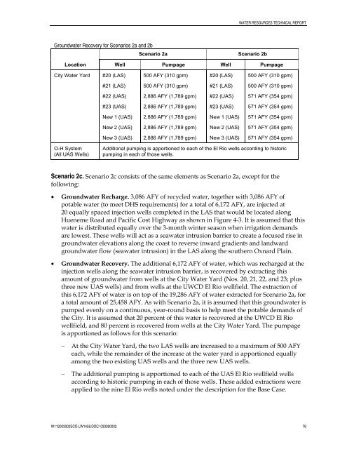
WATER RESOURCES TECHNICAL REPORTGroundwater Recovery for Scenarios 2a and 2bScenario 2aScenario 2bLocation Well Pumpage Well Pumpage<strong>City</strong> Water Yard#20 (LAS)500 AFY (310 gpm)#20 (LAS)500 AFY (310 gpm)#21 (LAS)500 AFY (310 gpm)#21 (LAS)500 AFY (310 gpm)#22 (UAS)2,886 AFY (1,789 gpm)#22 (UAS)571 AFY (354 gpm)#23 (UAS)2,886 AFY (1,789 gpm)#23 (UAS)571 AFY (354 gpm)New 1 (UAS)2,886 AFY (1,789 gpm)New 1 (UAS)571 AFY (354 gpm)New 2 (UAS)2,886 AFY (1,789 gpm)New 2 (UAS)571 AFY (354 gpm)New 3 (UAS)2,886 AFY (1,789 gpm)New 3 (UAS)571 AFY (354 gpm)O-H System(All UAS Wells)Additional pumping is apportioned to each <strong>of</strong> the El Rio wells according to historicpumping in each <strong>of</strong> those wells.Scenario 2c. Scenario 2c consists <strong>of</strong> the same elements as Scenario 2a, except for thefollowing:• Groundwater Recharge. 3,086 AFY <strong>of</strong> recycled water, together with 3,086 AFY <strong>of</strong>potable water (to meet DHS requirements) for a total <strong>of</strong> 6,172 AFY, are injected at20 equally spaced injection wells completed in the LAS that would be located alongHueneme Road and Pacific Cost Highway as shown in Figure 4-3. It is assumed that thiswater is distributed equally over the 3-month winter season when irrigation demandsare lowest. These wells will act as a seawater intrusion barrier to create a focused rise ingroundwater elevations along the coast to reverse inward gradients and landwardgroundwater flow (seawater intrusion) in the LAS along the southern <strong>Oxnard</strong> Plain.• Groundwater Recovery. The additional 6,172 AFY <strong>of</strong> water, which was recharged at theinjection wells along the seawater intrusion barrier, is recovered by extracting thisamount <strong>of</strong> groundwater from wells at the <strong>City</strong> Water Yard (Nos. 20, 21, 22, and 23; plusthree new UAS wells) and from wells at the UWCD El Rio wellfield. The extraction <strong>of</strong>this 6,172 AFY <strong>of</strong> water is on top <strong>of</strong> the 19,286 AFY <strong>of</strong> water extracted for Scenario 2a, fora total amount <strong>of</strong> 25,458 AFY. As with Scenario 2a, it is assumed that this groundwater ispumped evenly on a continuous, year-round basis to help meet the potable demands <strong>of</strong>the <strong>City</strong>. It is assumed that 20 percent <strong>of</strong> this water is recovered at the UWCD El Riowellfield, and 80 percent is recovered from wells at the <strong>City</strong> Water Yard. The pumpageis apportioned as follows for this scenario:−−At the <strong>City</strong> Water Yard, the two LAS wells are increased to a maximum <strong>of</strong> 500 AFYeach, while the remainder <strong>of</strong> the increase at the water yard is apportioned equallyamong the two existing UAS wells and the three new UAS wells.The additional pumping is apportioned to each <strong>of</strong> the UAS El Rio wellfield wellsaccording to historic pumping in each <strong>of</strong> those wells. These added extractions wereapplied to the nine El Rio wells noted under the description for the Base Case.W112003002SCO LW1458.DOC/ 033390002 78