RULES DET NORSKE VERITAS (DNV) = STRUCTURES = - Boat Design Net
RULES DET NORSKE VERITAS (DNV) = STRUCTURES = - Boat Design Net
RULES DET NORSKE VERITAS (DNV) = STRUCTURES = - Boat Design Net

Create successful ePaper yourself
Turn your PDF publications into a flip-book with our unique Google optimized e-Paper software.
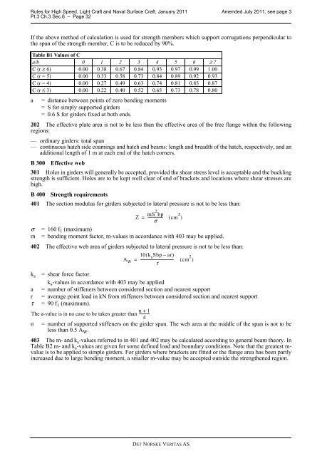
Rules for High Speed, Light Craft and Naval Surface Craft, January 2011 Amended July 2011, see page 3Pt.3 Ch.3 Sec.6 – Page 32If the above method of calculation is used for strength members which support corrugations perpendicular tothe span of the strength member, C is to be reduced by 90%.Table B1 Values of Ca/b 0 1 2 3 4 5 6 ≥ 7C (r ≥ 6) 0.00 0.38 0.67 0.84 0.93 0.97 0.99 1.00C (r = 5) 0.00 0.33 0.58 0.73 0.84 0.89 0.92 0.93C (r = 4) 0.00 0.27 0.49 0.63 0.74 0.81 0.85 0.87C (r ≤ 3) 0.00 0.22 0.40 0.52 0.65 0.73 0.78 0.80a = distance between points of zero bending moments= S for simply supported girders= 0.6 S for girders fixed at both ends.202 The effective plate area is not to be less than the effective area of the free flange within the followingregions:— ordinary girders: total span— continuous hatch side coamings and hatch end beams: length and breadth of the hatch, respectively, and anadditional length of 1 m at each end of the hatch corners.B 300 Effective web301 Holes in girders will generally be accepted, provided the shear stress level is acceptable and the bucklingstrength is sufficient. Holes are to be kept well clear of end of brackets and locations where shear stresses arehigh.B 400 Strength requirements401 The section modulus for girders subjected to lateral pressure is not to be less than:Z =mS 2 bp----------------σ( cm 3 )σ =160 f 1 (maximum)m = bending moment factor, m-values in accordance with 403 may be applied.402 The effective web area of girders subjected to lateral pressure is not to be less than:10( k s Sbp – ar)A W = ------------------------------------ ( cm 2 )τk s = shear force factor.k s -values in accordance with 403 may be applieda = number of stiffeners between considered section and nearest supportr = average point load in kN from stiffeners between considered section and nearest supportτ =90 f 1 (maximum).The a-value is in no case to be taken greater than -----------n + 14n = number of supported stiffeners on the girder span. The web area at the middle of the span is not to beless than 0.5 A W .403 The m- and k s -values referred to in 401 and 402 may be calculated according to general beam theory. InTable B2 m- and k s -values are given for some defined load and boundary conditions. Note that the greatest m-value is to be applied to simple girders. For girders where brackets are fitted or the flange area has been partlyincreased due to large bending moment, a smaller m-value may be accepted outside the strengthened region.<strong>DET</strong> <strong>NORSKE</strong> <strong>VERITAS</strong> AS