Ascot Owner's Manual - Pine Tree Stove Shoppe
Ascot Owner's Manual - Pine Tree Stove Shoppe
Ascot Owner's Manual - Pine Tree Stove Shoppe

You also want an ePaper? Increase the reach of your titles
YUMPU automatically turns print PDFs into web optimized ePapers that Google loves.
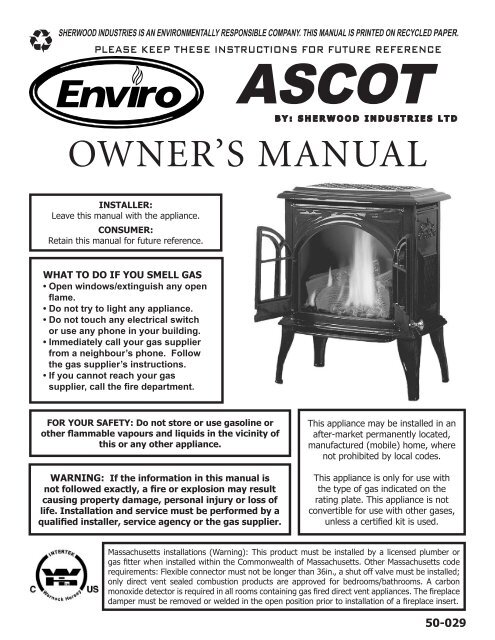
SHERWOOD INDUSTRIES IS AN ENVIRONMENTALLY RESPONSIBLE COMPANY. THIS MANUAL IS PRINTED ON RECYCLED PAPER.PLEASE KEEP THESE INSTRUCTIONS FOR FUTURE REFERENCEASCOTB Y : S H E R W O O D I N D U S T R I E S L T DOWNER’S MANUALINSTALLER:Leave this manual with the appliance.CONSUMER:Retain this manual for future reference.WHAT TO DO IF YOU SMELL GAS• Open windows/extinguish any openflame.• Do not try to light any appliance.• Do not touch any electrical switchor use any phone in your building.• Immediately call your gas supplierfrom a neighbour’s phone. Followthe gas supplier’s instructions.• If you cannot reach your gassupplier, call the fire department.FOR YOUR SAFETY: Do not store or use gasoline orother flammable vapours and liquids in the vicinity ofthis or any other appliance.WARNING: If the information in this manual isnot followed exactly, a fire or explosion may resultcausing property damage, personal injury or loss oflife. Installation and service must be performed by aqualified installer, service agency or the gas supplier.This appliance may be installed in anafter-market permanently located,manufactured (mobile) home, wherenot prohibited by local codes.This appliance is only for use withthe type of gas indicated on therating plate. This appliance is notconvertible for use with other gases,unless a certified kit is used.Massachusetts installations (Warning): This product must be installed by a licensed plumber orgas fitter when installed within the Commonwealth of Massachusetts. Other Massachusetts coderequirements: Flexible connector must not be longer than 36in., a shut off valve must be installed;only direct vent sealed combustion products are approved for bedrooms/bathrooms. A carbonmonoxide detector is required in all rooms containing gas fired direct vent appliances. The fireplacedamper must be removed or welded in the open position prior to installation of a fireplace insert.50-029
Safety PrecautionsFOR SAFE INSTALLATION AND OPERATION OF YOUR “ENVIRO” HEATER,PLEASE CAREFULLY READ THE FOLLOWING INFORMATION:• All ENVIRO gas-fired appliances must be installedin accordance with their instructions. Carefully read allthe instructions in this manual first. Consult the buildingauthority having jurisdiction to determine the need fora permit prior to commencing the installation.• NOTE: Failure to follow these instructions couldcause a malfunction of the fireplace, which couldresult in death, serious bodily injury, and/or propertydamage.• Failure to follow these instructions may also voidyour fire insurance and/or warranty.GENERAL• Installation and repair should be done by aqualified service person. The appliance should beinspected before the first use and, at least, annuallyby a qualified service person. More frequentcleaning may be required due to excessive lint fromcarpeting, bedding material, etc. It is imperative thecontrol compartments, burners and circulating airpassageways of the appliance be kept clean.• Due to high temperatures, the appliance shouldbe located out of high traffic areas and away fromfurniture and draperies.Children and adults should be alerted to thehazards of high surface temperatures andshould stay away to avoid burn or clothingignition.• Young children should be carefully supervisedwhen in the same room as the appliance.• Clothing or other flammable materials should notbe placed on or near the appliance.FOR YOUR SAFETY• Installation and service must be performed by aqualified installer, service agency or gas supplier.• This installation must conform to local codes or, inthe absence of local codes, to the current CAN/CGA-B149 installation code (Canada) or National Fuel GasCode ANSI Z223.1.2 (USA)• To prevent injury, do not allow anyone who isunfamiliar with the stove to operate it.• To prevent injury, if the pilot or pilot andburners have gone out on their own, open theglass door and wait 5 minutes to air out beforeattempting to re-light the stove.• Always keep the area around these appliancesclear of combustible material, gasoline and otherflammable liquids and vapours.• These appliances should not be used as a dryingrack for clothing or for hanging Christmas stockings/decorations.• Due to the paint curing on the stove, a faint odorand slight smoking will likely be noticed when thestove is first used. Open a window until the smokingstops.Always connect this gas stove to a vent system andvent to the outside of the building envelope. Nevervent to another room or inside the building. Make surethe specified vent pipe is used, properly sized and ofadequate height to provide sufficient draft. Inspectthe venting system annually for blockage and signs ofdeterioration.WARNING: Failure to position the parts in accordancewith the diagrams in this booklet, or failure to use onlyparts specifically approved with this appliance, mayresult in property damage or personal injury.WARNING: Do not operate with the glass frontremoved, cracked or broken. Replacement of theglass should be done by a licensed or qualified serviceperson.• Never use solid fuels such as wood, paper,cardboard, coal, or any flammable liquids, etc., in thisappliance.• Do not use this heater if any part has been underwater. Immediately call a qualified service technicianto inspect the heater and to replace any part of thecontrol or gas control systems that have been underwater.• Do not abuse the glass by striking it or slammingthe door shut.2
Table of ContentsSafety Precautions....................................................................................................2Table of Contents......................................................................................................3Codes And Approvals.................................................................................................4Specifications...........................................................................................................5Dimensions....................................................................................................5Rating Label Location.....................................................................................5Operating Instructions...............................................................................................6Lighting Instructions.......................................................................................6Pilot Light......................................................................................................7Remote controls (Optional).............................................................................7Blower Speed (Optional).................................................................................7Normal Sounds During Operation....................................................................7Maintenance And Service...........................................................................................8Routine Maintenance......................................................................................8Cleaning The Glass.........................................................................................8Cleaning The Firebox......................................................................................8Change Battery in Ignition Module...................................................................8Replacing Glass..............................................................................................9Glass Door Removal.......................................................................................9Burner Removal.............................................................................................9Fuel Conversion............................................................................................10Initial Installation....................................................................................................12Preparation For Installation...........................................................................12Clearances to Combustibles...........................................................................12Planning Your Installation.............................................................................13Vent Termination Restrictions........................................................................14Fireplace Horizontal Vent Kit 50-1235.............................................................15Other Approved Vent Parts............................................................................16Vent Restrictor Setting..................................................................................18Horizontal Installation...................................................................................19Vertical Installation.......................................................................................22Freestanding Drafthood Adaptor - 50-841......................................................25Hearth Mount Installation.............................................................................28Gas Line Connection and Testing...................................................................29Electrical Requirements.................................................................................30Secondary Installation.............................................................................................31Installation of Log Set and Embers................................................................31Installation of Optional Blower.......................................................................33Trouble Shooting.....................................................................................................34Parts List................................................................................................................35Parts Diagram.........................................................................................................38Warranty................................................................................................................39Installation Data Sheet............................................................................................423
Codes And ApprovalsDIRECT VENT ONLY: This type is identified by the suffix DV. This appliance draws all of its air forcombustion from outside the dwelling, through a specially designed vent pipe system.** TOP VENT DV ONLY** This appliance has been tested and approved for installations from 0 feet to4500 feet (1372 m) above sea level.In the USA: The appliance may be installed at higher altitudes. Please refer to your American GasAssociation guidelines which state: the sea level rated input of Gas Designed Appliances installed atelevations above 2000 (610 m) feet is to be reduced 4% for each 1000 feet (305 m) above sea level.Refer also to local authorities or codes which have jurisdiction in your area regarding the de-rateguidelines.In Canada: When the appliance is installed at elevations above 4500 feet (1372 m), the certified highaltitude rating shall be reduced at the rate of 4% for each additional 1000 feet (305 m).• This appliance has been tested by INTERTEK (Warnock Hersey) and found to comply with theestablished VENTED GAS FIREPLACE HEATER standards in CANADA and the USA as follows:VENTED GAS FIREPLACE HEATER (ASCOT DV; NG/LPG)TESTED TO: ANSI Z21.88a-2003/CSA 2.33a-2003 VENTED GAS FIREPLACE HEATERSCAN/CGA 2.17-M91 GAS FIRED APPLIANCES FOR HIGH ALTITUDESCSA P.4.1-02 TESTING METHOD FOR MEASURING ANNUAL FIREPLACE EFFICIENCYThis ENVIRO ASCOT Fireplace:• Has been certified for use with either natural or propane gases. (See rating label.)• Is not for use with solid fuels.• Is approved for bedroom or bed sitting room. (IN CANADA: must beinstalled with a listed wall thermostat. IN USA: see current ANSI Z223.1for installation instructions.)• Must be installed in accordance with local codes. If none exist, use currentinstallation code CAN/CGA B149 in Canada or ANSI Z223.1/NFPA 54 in theUSA.• Must be properly connected to an approved venting system and notconnected to a chimney flue serving a separate solid-fuel burningappliance.IMPORTANT NOTICE (Regarding first fire up): When the unit is turnedon for the first time, it should be turned onto high without the fan on forthe first 4 hours. This will cure the paint, logs, gasket material and otherproducts used in the manufacturing process. It is advisable to open awindow or door, as the unit will start to smoke and can irritate some people.After the unit has gone through the first burn, turn the unit off including thepilot, let the unit get cold then remove the glass door and clean it with agood gas fireplace glass cleaner, available at your local ENVIRO dealer.4
SpecificationsDIMENSIONS: Height: 24 1 /16 inches (611 mm)Width: 19 1 /16 inches (484 mm)Depth: 15 5⁄8 inches (397 mm)Center of flue to ground without leveling legs:18 3⁄8 inches (467 mm)Center of flue to ground with leveling legs (approx.):19 inches (483 mm)Figure 1. Dimensions of the <strong>Ascot</strong>.RATING LABEL LOCATION:The Rating Label is located on a plate hang on the back left of the unit.5
LIGHTING INSTRUCTIONS:Operating InstructionsFOR YOUR SAFETY READ COMPLETELY BEFORE OPERATING.Hot while operating. Do not touch. Keep children, clothing,CAUTION: furnit ure, gasoline or other flammable vapors away.FOR YOUR SAFETY: Do not operate this fireplace with the glass removed, cracked or broken.Replacement of this glass should be done by a licensed or qualified person! This appliance needs freshair for safe operation and must be installed with provisions for combustion and ventilation air.See installation and operating instructions manual. Keep burner and control compartment clean .WARNING: Improper installation, adjustment, alteration, service or maintenance can cause propertydamage, personal injury, or loss of life. Refer to owners manual. Installation and service must beperformed by qualified installer, service agency or the gas supplier.FOR YOUR SAFETY READ BEFORE OPERATINGWARNING: IF YOU DO NOT FOLLOW THESE INSTRUCTIONS EXACTLY, A FIRE OR EXPLOSION MAY RESULT CAUSINGPROP ERTY DAMAGE, PERSONAL INJURY OR LOSS OF LIFE.A) This appliance is e quippe d with a pilot, which mustbe litbyhand b y following these instructions e xactly.If you cannot re ach your gas supp lier, call the fire departm ent.B) BEFORE LIGHTING smell all around the appliance areaC)for gas and n ext to the floor because some gas is heavi erthan air and will se ttle on the floor.WHAT TO DO IF YOU SMELL GAS:Do not try to light any a pplian ce. Do not touch a ny electricalswitch: do not use any phone in you r building.D)Immediately call your gas sup plier from a neighbors p hone.Follo w the gas supplie rs instr uctions.1. STOP! Read th e safe ty information above on th is labe l.2. Turn off all electrical power to this applian ce.3. Turn off the gas contr ol knob clockwise to the offposition.4. Open door. Wa it five (5) minutes to clear outany gas.Cl ose do or. If you sme ll gas, includ ing ne ar the floor ,STOP! Follow “ B” in the above safety information.If you do not smell gas go to the ne xt ste p5. Fin d pilo t-locate d to th e righ t behin d the side log. Turnthe gas controlkn ob cou nter-clockwise to “PILOT”.Push the gas co ntrol inful ly and hold, Keep knobdepressed for a bout 30 seco nds afterpilot is lit. Release kno b. If p ilot goes out,rep eatsteps 4 through 5.LIGHTING INSTRUCTIONSUse only your ha nd to p ush in or tu rn the gas co ntrol knob,Neve r use tools. If the knob will not push in or turn byhand , do n ot try to rep air it.Call a qual ified service techn ician. Force or attempte drepair may result in a fire or explosion.Do n ot use thisa pplian ce if any part has b een u nder water.Immediately call a qualified service technician to inspe ctthe a ppliance an d to replace any pa rt of the con trol systemand any ga s con trol which ha s been unde r water.WARNING : this gas valve ha s a lockout device, which willn ot allow the pilot burner to be relit until the ther mocoupleh as cooled. If the knob does not po p up when released,stop and imme diately call yo ur service technician or gassupplier.If the pilot does not stay lit after several tries, turn the gascontrol knob to “OFF” and call your service technician org as supplier.6. Turn the gas control knob counter clockwise to the“ON” position. Flip the burner switch to“ON” THEN TURN THE “HI/LOW” knob to the desired setting.7. Turn on the ele ctrical power to the unit.TO TURN OFF GAS TO APPLIANCE1. Fli p burn er switch to “OFF”2. Turn the gasco ntrol knob clockwise to th e “OF F”po sition3 . Turn off all electrical po wer to the ap pliance if service i stobe performe d.ACLIE -1Figure 2. Lighting instruction label.6
Operating InstructionsFor Your Safety, Read Safety Precautions AndLighting Instructions Before OperatingPILOT LIGHT:1. Turn off the gas to the fireplace. If not recently done, remove the glass and let the unit air outfor at least five (5) minutes to clear out any gas. Turn on gas to the heater. Leak test all jointswith soapy water. NEVER USE AN OPEN FLAME FOR LEAK TESTING.2. Start the pilot by pressing the gas control knob and turning it to PILOT.While holding the gas control knob in, press the piezo ignitor severaltimes until the pilot light starts. Hold the gas control knob in for thirty (30)seconds. Check that the pilot has fully engulfed the thermocouple assembly(see Figure 3).3. Start the main burner by turning the gas control knob to ON and then turnthe rocker switch to ON. Check that all burner ports have flame.4. Leak test all gas joints again.Figure 3. Pilot flame.REMOTE CONTROLS (OPTIONAL):This fireplace can use an optional remote control or an optional cordless wall thermostat. If either ofthese are to be used to control the fireplace for the majority of the time, leave the ON/OFF switch (on thecontrol panel) in the remote/thermostat position. Consult the instructions included with the remote/wallthermostat for operation guidelines.BLOWER SPEED (OPTIONAL):The blower will come on only when the fireplace is up to temperature (approximately 20 minutes). Thespeed of the fan can be changed by turning the fan control knob. To turn the blower off, turn the knobCOUNTER CLOCKWISE until it “clicks” off.It is advisable not to operate the blower below 1/3 speed as it puts a strain on the windings of the blowerand running the blower at lower speeds could also cause premature fan failure.NORMAL SOUNDS DURING OPERATION:Component<strong>Ascot</strong>BurnerTemperature SensorPilot FlameBlower / FanGas Control ValveSound & ReasonTable 1: Normal SoundsCreaking when heating up or cooling down.Light pop or poof when turned off; this is more common with LP units.Clinking when it senses to turn the blower on or off.Quiet whisper while the pilot flame in on.Air movement that increase and decreases with the speed of the blower. Theblower is pushing the heat from the fireplace into the room.Dull click when turning on or off, this is the valve opening and closing.7
Maintenance And ServiceROUTINE MAINTENANCE:At least once a year, run through the following procedures to ensure the system is clean and workingproperly. Check the burner to see if all the ports are clear and clean. Check the pilot to make sure it is notblocked by anything. The pilot flame should be blue with little or no yellow on the tips.Warning: Clearances must be sufficient to allow access for maintenance and serviceWarning: Failure to position the parts in accordance with this manual, or failure to use only partsspecifically approved with this appliance may result in property damage or personal injury.The venting system must be periodically examined; it is recommended the examination is done by aqualified agency.CLEANING THE GLASS:When the fireplace has cooled, remove the face of the fireplace along with the glass. See MAINTENANCEAND SERVICE - GLASS DOOR REMOVAL. Check the gasket material on the back of the glass, making sure that itis attached and intact.It will be necessary to clean the ceramic glass periodically. During a cold start up, condensation willsometimes form on the glass. This is a normal condition with all fireplaces. However, this condensationcan allow dust and lint to cling to the glass surface. Initial paint curing of the appliance can leave a slightfilm behind the glass, a temporary problem. The glass will need cleaning initially after the first 4 hoursof use and again about two (2) weeks after installation. Use a mild glass cleaner and a soft cloth;abrasive cleaners will damage the glass and enamel surfaces. Depending on the amount of use,the glass should require cleaning no more than two or three times a season. Do not clean the glasswhen it is hot.CLEANING THE FIREBOX:Remove the logs carefully, as they are very fragile. Gently remove all the embers and rock wool andplace on a paper towel. Vacuum the bottom of the firebox thoroughly. Carefully clean any dust off thelogs and remove any lint from the burner and pilot. At this time, inspect the burner pan for cracking orsevere warping. If a problem is suspected, contact the dealer. Check the logs for deterioration or largeamounts of soot; a small amount on the bottom side of the logs is normal. Replace the logs and embersas in the LOG SET AND EMBER INSTALLATION section. If new/more embers and rock wool are required, contactyour nearest ENVIRO dealer.CHANGE BATTERY IN IGNITION MODULE:If the unit does not spark when lighting, the battery in theelectronic ignition could need replacing.The ignition module is located at the far left behind the valvecover (see Figure 4). Remove the battery cover, located on theleft side of the module, and replace the AA battery.Reinstall the battery cover and check for spark by depressing thepilot knob located on the control panel.Ignition ModuleFigure 4. SIT Valve on <strong>Ascot</strong>.8
Maintenance And ServiceREPLACING GLASS:The glass in the fireplace is a high temperature ceramic. If the glass is damaged in any way, a factoryreplacement is required (see PARTS LIST - COMPONENTS). Wear gloves when handling damaged glass doorassembly to prevent personal injury. When the glass door assembly is being transported, it must bewrapped in newsprint and tape and/or a strong plastic bag. Do not operate with the glass front removed,cracked or broken. Removal and replacement of the glass from the door must be done by a licensed orqualified service person. The glass must be purchased from an ENVIRO dealer. No substitutematerials are allowed.To Replace: Open door, and remove the glass carefully. Install the new piece of glass with the large bulbin the gasket tape against the unit. Place the joint in the tape in a bottom corner. Close door.GLASS DOOR REMOVAL:Turn unit off and wait until the appliance has cooled down.Remove the cast iron top from the unit by lifting straight up. Liftthe two door handles located on either side of the door and liftthe glass door assembly straight up and out. Carefully open thetwo doors and remove if necessary.Ensure the door is properly fastened after cleaning beforeattempting to re-light the appliance.Figure 5. Removing inner glass door.BURNER REMOVAL:1. Remove the glass as shown in the MAINTENANCE AND SERVICE - GLASS DOOR REMOVAL.2. Carefully remove the log set and ember material.3. Remove the two (2) screws at the back of the firebox that hold the log support tray in place (seeFigure 6). Remove the support tray from the firebox4. Remove the screw located on the right side of theburner that holds the burner to the chassis insidethe fire box. Remove the burner tray from thefirebox.Figure 6. Removing log support tray.9
Maintenance And ServiceFUEL CONVERSION:TO BE INSTALLED BY A QUALIFIED SERVICE AGENCY ONLYPlease read and understand these instructions before installing.Warning: This conversion kit shall be installed by a qualified service agency in accordancewith the manufacturer’s instructions and all applicable codes and requirements of theauthority having jurisdiction. If the information in these instructions is not followedexactly, a fire, explosion or production of carbon monoxide may result causing propertydamage, personal injury or loss of life. The qualified service agency is responsible forthe proper installation of this kit. The installation is not proper or complete until theoperation of the converted appliance is checked as specified in the manufacturer’sinstructions supplied with the kit.Kit Parts List:1 - Orifice (NG - #48 DMS or LP - #57 DMS)1 - Pilot Injector (NG 0.62 mm; LP 0.35 mm)1 - Installation instruction sheet1 - Conversion labelCarefully inspect all parts supplied with this conversion kit. If any parts have been damaged or aremissing, contact your dealer, distributor or courier company to have them replaced before starting thisinstallation.Conversion Kit Installation:1. Turn control knob on the gas valve to the “OFF” position and shut the gas supply off at the shut-offvalve upstream of the unit. CAUTION: The gas supply must be shut off prior to disconnecting theelectrical power and before proceeding with the conversion. Allow the valve and unit to cool downto room temperature.2. Remove the glass as shown in the MAINTENANCE AND SERVICE - GLASS DOOR REMOVAL.3. Carefully remove the log set and ember material if they are installed.4. Remove the burner as shown in the MAINTENANCE AND SERVICE - BURNER REMOVAL.5. Convert the burner orifice(s):a) Remove the main burner orifice with a 1⁄2 inch deep socket.b) Put a bead of pipe-thread sealant or approved Teflon tape on the orificethreads before installing into the brass elbow.c) Install the new orifice(s) from the kit into the brass elbow.6. Convert the pilot injector:a) Pull the pilot hood straight up to access the pilot injector.b) Using a 5 /32” or 4 mm Allen key, remove the pilot injector.c) Install the new pilot injector supplied with this conversion kit. Simply screwthe new injector inside the pilot hood using the Allen key,d) Reinstall the hood by placing the hood on the assembly, line up the keyway, and snap into place.Figure 7: Removingvalve cap.10
Maintenance And Service7. Convert the SIT gas valve:a) Remove the black protection cap from the HI/LO knob by hand shown in Figure 7.b) Insert a 5 /32” or 4 mm Allen wrench into thehexagonal key-way of the screw (see Figure 8),rotate it counter-clockwise until it is free andextract it.c) Check that the screw is clean and if necessaryremove dirt.Loosend) Flip the screw (refer to Figure 9).e) Using the Allen wrench as shown in Figure 8,rotate the screw clockwise until a torque of 9 inchlbs. WARNING! Do not over tighten the screw.It is recommended that you grip the wrench bythe short side.f) Verify that if the conversion is from NG to LPG,the screw must be re-assembled with the red o-ring visible (refer to Figure 10). If the conversionis from LPG to NG, the red o-ring of the screwmust be not visible.TightenFigure 8: Removing valve screw.g) Re-attach the black protectioncap that was removed in step a(Figure 7).8. Reinstall the burner, brick panels,log set, embers, and glass door.Also refer to SECONDARY INSTALLATION- INSTALLING LOG SET AND EMBERS. Whenre-installing the burner, ensure thatthe burner to pilot hood relationshipRed o-ringis visibleLPG ConfigurationRed o-ringis not visibleFigure 10: O-ring on valve screw.is similar to what is shown in Figure 11. On some units you will need to payspecial attention when installing the burner that the venturi adjustment rodis properly installed into the venturi adjustment piece welded to the burnerventuri tube9. Reconnect the main gas line if it was disconnected and open the shut-off valveat the gas line to the unit.10. Use a small brush to apply a warm soapy water solution to all gas connections(use a half dish soap and half warm water). If a gas leak is present, bubblingwill occur. Gas leaks can be repaired by using an approved pipe thread sealantor approved Teflon tape. NEVER USE AN OPEN FLAME WHEN TESTING FORLEAKS.Figure 9: Flip valvescrew.Figure 11. Ignitorassembly beside theburner.11. Reconnect the electrical power to the unit.12. Relight the main burner in both the “HI” and “LO” positions to verify proper burner ignition andoperation and proper flame appearance. Also refer to SECONDARY INSTALLATION - LOG SET AND EMBERSINSTALLATION for a flame appearance picture.13. MAKE SURE that the conversion label is installed on or close to the rating label to signify that theunit has been converted to a different fuel type.11
WARNING:Initial InstallationQUALIFIED INSTALLERS ONLYOperation of this heater when not connected to a properly installed and maintained venting system canresult in carbon monoxide (CO) poisoning and possible death.PREPARATION FOR INSTALLATION:• Remove the packaging from the appliance, and check to make sure there is no damage. If damage isfound, please report it to both the carrier and your dealer as soon as possible.• Before beginning, carefully check the glass door and the log set• Locate a position where the flue system of the stove can be properly installed without damaging theintegrity of the building; e.g. cutting a wall or ceiling joist.• Check stove and flue system clearance requirements.• Locate the stove where it can be accessed by a gas supply line.• Locate the stove in a large and open room that is centrally located in the house. This will optimize heatcirculation and comfort.• As the stove can be equipped with a convection fan, ensure that an electrical outlet is within 6 ft (1.8m) of the stove.• The flow of combustion and ventilation air must not be obstructed.CLEARANCES TO COMBUSTIBLES:A) Sidewall to unit 10 inches (254 mm)B) Backwall to unit 21⁄2 inches (64 mm)C) Corner to unit 21⁄2 inches (64 mm)D) Ceiling bottom of unit 60 inches (1524 mm)E) Floor 0 inches (0 mm)Note: Must have hearth pad if installed on acarpeted surface.If this unit is installed in an alcove the alcove must meetthese minimum dimensions:Width 48 inches (1219 mm)Height 60 inches (1524 mm)Maximum Depth 24 inches (610 mm) Figure 12: Clearances to combustibles.CLEARANCES MUST BE SUFFICIENT TO ALLOW ACCESS FOR MAINTENANCE AND SERVICE.12
PLANNING YOUR INSTALLATION:Initial InstallationQUALIFIED INSTALLERS ONLYWhen planning your installation, it will be necessary to select the proper length of vent pipe for yourparticular requirements. It is important to note when passing through a wall, the maximum allowablewall thickness is 10 inches (25.4 cm), 11⁄2 inches (3.8 cm) clearance to combustibles must be maintained.Select the amount of vertical rise desired for “vertical-to-horizontal” type installations. To determinethe length of vent pipe required for vertical installations, measure the distance from the appliance flueoutlet to the ceiling, the ceiling thickness, the vertical rise through the attic or second story, and allowfor sufficient vent height above the roofline. For two story applications, a fire stop is required at eachfloor level. If an offset is needed in the attic, additional pipe and elbows will be required. To connect theventing system to the appliance flue outlet, a twist-lock adapter is built into the appliance at the factory.Refer to INITIAL INSTALLATION - VENT CONFIGURATION AND RESTRICTOR SETTINGS for venting parameters.Your total vent pipe length must be within the shaded area of Figure 36. If a 90° elbow is used in thehorizontal plane, 36” (91.4 cm) must be subtracted from the allowable horizontal run.There are two (2) basic types of Direct Vent System installations. The two (2) types of installations areshown below.Round SupportBox/Wall ThimbleVerticalTerminationHorizontalTerminationStorm CollarFlashingPipelength90° ElbowCeiling FirestopRound SupportBox/Wall ThimbleCathedral CeilingSupport BoxPipelengthPipelengthFigure 13: Common Horizontal Installation.PipelengthFigure 14: Common Vertical Installation.13
VENT TERMINATION RESTRICTIONS:Initial InstallationQUALIFIED INSTALLERS ONLYOND EL B CFBFixedClosedOpenableBOpenableAJBFixedClosedTermination Cap Air Supply Inlet G Gas MeterHGIMRestriction Zone(Termination not allowed)KGAFigure 15. Vent Termination Restrictions, refer to Table 2.Letter Canadian Installation 1 US Installation 2 DescriptionA 12 in (30 cm) Clearance above grade, verandah, porch, deck, or balcony.B 12 in (30 cm) 9 in (23 cm) Clearance from window or door that may be opened.C 12 in (30 cm)* Clearance from permanently closed window (to preventcondensation).D 24 in (60 cm)* Vertical clearance to ventilated soffit located above theterminal, within a horizontal distance of 2 ft (60 cm) fromcenter line of terminal.E 18 in (45 cm)* Clearance to unventilated soffit.F 12 in (30 cm)* Clearance to outside corner.G 12 in (30 cm)* Clearance to inside corner.H3 ft (91 cm) within a height of15 ft (4.5 m) above the meter/regulator assemblyTable 2: Vent termination clearances, refer to Figure 15.3 ft (91 cm) within a height of15 ft (4.5 m) above the meter/regulator assembly*Clearance to each side of center line extended abovemeter/regulator assembly.I 3 ft (91 cm) 3 ft (91 cm)* Radial clearance around service regulator vent outlet.J 12 in (30 cm) 9 in (23 cm) Clearance to non-mechanical air supply inlet to building, orthe combustion air inlet to any other appliance.K 6 ft (1.83 m) 3 ft (91 cm) above if within 10ft (3 m) horizontallyClearance to mechanical air supply inlet.L 7 ft (2.13 m )t 7 ft (2.13 m) *t Clearance above paved sidewalk or paved driveway locatedon public property.M 12 in / 30 cm + 12 in / 30 cm* + Clearance under verandah, porch, deck, or balcony.N 12 in (30 cm)* Clearance horizontally to any surface (such as an exteriorwall) for vertical terminations.O 12 in (30 cm) Clearance above roof line for vertical terminations.1 In accordance with the current CSA B149, Natural Gas and Propane Installation Code.2 In accordance with the current ANSI Z223.1 NFPA 54, National Fuel Gas Code.* These numbers are only estimates. Clearance in accordance with installation codes and the requirements of the gas supplier.t A vent shall not terminate directly above a side walk or paved driveway that is located between two single family dwellings and it serves both dwellings.+ Permitted only if verandah, porch, deck, or balcony is fully open on a minimum of two sides beneath the floor.NOTE: Venting terminals shall not be recessed into walls or siding.14
FIREPLACE HORIZONTAL VENT KIT 50-1235:KIT COMPONENTS:Initial InstallationQUALIFIED INSTALLERS ONLYPlease read and understand these instructions before installing. Failure to followthese instructions carefully could cause property damage or personal injury.Qnty Description Qnty Description1 Horizontal direct vent termination cap 4 Wire spacers1 Flue collar adapter 1 4 oz tube Mill-Pac Sealant1 Wall thimble 1 4 oz tube RTV silicone1 5’ (190 cm) length of Ø4” (10 cm) double walled flex pipe 12 9 /16” tech screws1 5’ (190 cm) length of Ø65⁄8” (16.8 cm) double walled flex pipe 8 11⁄2” wood screwsPlease ensure that all components are supplied with this kit. If components are missing or havebeen damaged, contact your dealer, distributor, or courier company. Do not attempt the installation ifcomponents are missing or damaged.INSTALLATION INSTRUCTIONS:1. Plan your installation and clearances to combustibles. Decide on a location for the unit that will meetthe clearances noted in the venting section, and any or all local code requirements.2. Set the appliance in the desired location. Determine if any wall studs, electrical wiring, or plumbingpipes are in the way of the venting system as it passes through the exterior wall. The fireplace locationshould be adjusted if obstructions are found in the wall.3. Project a line from the center point of the flue outlet upward and outward to the desired flue outletlocation on the exterior wall. Using this center point, scribe a 10” (25.4 cm) hole or square on the wall.Cut the hole from the interior through the exterior wall surfaces.4. Frame the hole as shown in Figure 22.5. Trim the wall thimble to match the wall thickness as necessary. Install the wall thimble and secureit to the inner wall frame using four (4) 11⁄2” wood screws. If a wall isgreater than 8” (203mm) in depth, the clearance above the flex must be43⁄8” (111mm)6. Apply a bead of Mill-Pac Black sealant to the new Ø4” (10 cm) by 5” (12.5cm) provided flue collar adaptor. Press the flue collar into the flue outlet ofthe fireplace so that the Mill-Pac seals the flue collar to the flue outlet.7. Stretch both the Ø4” (10 cm) flex vent and the Ø65⁄8” (16.25 cm) flex intakeliner to the length needed to ensure the flex can be easily connected to thevent terminal.8. Slide the Ø65⁄8” (16.25 cm) flex intake linerover the flex vent. Install four (4) wirespacers around the flex pipe. Ensure thewire spacers are positioned at either end ofthe pipes, and at each end of any elbows inthe liners (refer to Figure 16 and 17).9. Install the flex pipe assembly throughthe wall thimble, ensure that this portionof pipe slides through the outside wallfar enough to connect onto the ventFigure 16: Wire Spacers. termination cap.Figure 17: Wire Spacer in Place.15
10. Apply a bead of Mill-Pac Black sealant tothe top section of the Ø4” (10 cm) by 5”(12.5 cm) flue collar adaptor previouslyinstalled into the fireplace flue outlet.Slide the Ø4” (10 cm) flex vent overthe flue collar and secure with three (3)sheet metal screws evenly spaced.11. Place a bead of high temperaturesilicone on the intake collar of thefireplace, slide the Ø65⁄8” (16.25 cm)flex intake liner over the collar, securethe flex liner with three (3) sheet metalscrews evenly spaced.12. On the outside of the exterior wall,apply a bead of Mill-Pac Black sealantto the Ø4” (10 cm) pipe of the ventterminal. Slide the flex liner onto thevent terminal and secure with three (3)sheet metal screws evenly spaced.13. Place a bead of high temperaturesilicone on the intake collar of the ventterminal, slide the Ø65⁄8” (16.25 cm)flex intake liner over the collar, securethe flex liner with three (3) sheet metalscrews evenly spaced.Initial InstallationQUALIFIED INSTALLERS ONLYFlue Pipe AdaptorWall ThimbleFire StopExhaust 4" Flex PipeWire SpacersHorizontal Vent TerminationCombusion Air 6 5 /8" Flex PipeWall FramingFigure 18: Installation of Fireplace Horizontal Vent Kit.14. Attach the vent terminal to the outside of the house using four (4) wood screws provided.15. Light the appliance and ensure proper operation.OTHER APPROVED VENT PARTS:16Table 3: Approved Vent ManufacturersManufacturer Trade Name Nominal SizesAmerican Metal Products AmeriVent Direct 4” - 6 5/8”Security Chimneys International LTD Secure Vent 4” - 6 5/8”Selkirk Metalbestos Direct-Temp 4” - 6 5/8”Simpson Dura-Vent Direct Vent GS 4” - 6 5/8”The <strong>Ascot</strong> fireplace has been tested and certified for use with AMERICAN METAL PRODUCTS “AMERIVENTDIRECT”, SIMPSON DURAVENT TYPE GS PIPE FOR GAS STOVES. SECURITY CHIMNEY’S “SECURE VENTDIRECT VENT SYSTEM” and SELKIRK “DIRECT-TEMP VENT SYSTEM” kits are available for horizontal andvertical venting. When using Simpson Duravent, it is recommended that, before installation, a bead ofRTV High Temperature Silicone should be applied to each outer vent joint, and Mil-Pac to each innerjoint. When planning an installation, it will be necessary to select the proper length of vent pipe for theparticular requirements.WARNING: Do not mix parts from different vent manufacturers’ systems.
Initial InstallationQUALIFIED INSTALLERS ONLYEXCEPTION TO WARNING: This product has been evaluated by Intertek for using a Direct Vent GSstarting collar in conjunction with Secure Vent, Direct-Temp, and Ameri Vent Direct venting systems. Useof these systems with the Direct Vent GS starting collar is deemed acceptable and does not affect theIntertek WH listing of the appliance.Table 4: Vent part numbers (Must state if galvanized or black wanted, PART NUMBERS).Direct Vent GS Direct-Temp Secure Vent Ameri Vent Direct Description908 4DT-6 SV4L6 6” pipe length4D77” pipe length907 4DT-9 9” pipe length906 4DT-12 SV4L12 4D12 12” pipe length904 4DT-24 SV4L24 4D2 24” pipe length903 4DT-36 SV4L36 4D3 36” pipe length902 4DT-48 SV4L48 4D4 48” pipe length945 4DT-EL45 SV4EBR45 4D45B 45° elbow, black990 4DT-EL90 SV4EBR90 4D90B 90° elbow, black950 4DT-VS SV4VS Vinyl siding standoff/sheild942 4DT-WT SV4RSN 4DWT Wall thimble953 4DT-SC SV4FC 4DSC Storm collar963 4DT-FS SV4BF 4DFSP Fire stop988 4DT-WS/B SV4BM 4DWS Wall strap/support/band970 4DT-HKA SV0SHK 4DHTK1Horizontal termination kit (SD: Basic Kit,SEL: Kit A, SC: Standard Kit)911 11” to 14 5⁄8” pipe, adjustable4DT-AJ 4D12A 4” to 10” pipe , adjustableSV4LA1211⁄2” to 12” pipe , adjustable943 4DT-AF6 4DF Flashing, 0/12 to 6/12 roof pitch943S 4DT-AF12 4DF12 Flashing, 7/12 to 12/12 roof pitchSV4FASV4FBFlashing, 1/12 to 7/12 roof pitchFlashing, 8/12 to 12/12 roof pitch943F SV4F Flat flashing980 4DT-VC SV4CGV 4DVC Vertical termination991 4DT-HVC High wind vertical termination984 4DT-HC SV4CHC 4DHC Horizontal square termination985 4DT-HHC High wind horizontal termination978 4DT-VKC SV0FAK 4DVTK Vertical termination kit971 4DT-HKB SV0SHK2 4DHTK2Horizontal termination kit(SD: Kit A, SEL: Kit B, SC: Kit)17
Initial InstallationVENT RESTRICTOR SETTING:To access restrictor plate, look at the left hand rear corner of the unit. There is a small rectangular holein the air jacket. Loosen the 1⁄4” hex head bolt and adjust to the correct setting. Slide the hex bolt to thenext setting and retighten the bolt to ensure the plate does not move15’ (4.57m) 10’ (3.05m)523415234Figure 19. Vent Restrictor Settings.1 Refer to Figure 20 to determine were the vent restrictor should beset for proper operation.The numbers in the chart represent the actual vent restrictorsettings. Although the numbers do not appear on the unit use thisguide to follow.Ensure that the setscrew is retightened and the unit is checked forproper operation.5’ (1.52m)2’ (0.62m) 2’ (0.62m)18”(0.46m)54321Vent Restrictor SettingsFigure 20. Possible Vent Configurations.Wait for the unit to warm up to operating temperature to ensure a proper and clean burning unit.NOTE: The total length of the vent pipes can not exceed 15 feet (4.6 m). Any combination of rise andrun can be used as long as it lays within the shaded area.18
HORIZONTAL INSTALLATION:Initial InstallationQUALIFIED INSTALLERS ONLYSTEP 1. Set the appliance in the desired location. Check to determine if wall studs or roof rafters arein the way when the venting system is attached. If this is the case, you may want to adjust thelocation of the appliance.STEP 2. Direct vent pipe and fittings are designed with special twist-lock connections. Assemble thedesired combination of black pipe and elbows to the appliance adapter with pipe seams orientedtowards the wall or floor, as much out of view as possible.SealantFemaleLockingLugsMaleLockingLugsFigure 21: Twist-Lock ConnectionNotes:Place a bead of Mil-Pac on theouter edge of the inner exhaustpipe (non-flared end). Place a beadof high temperature silicone onthe male edge of the outer pipe.Push the pipe sections completelytogether, then twist-lock onesection clockwise approximately 1⁄4turn, until the two sections are fullylocked. The female locking lugs willnot be visible from the outside, onblack pipe. They may be located byexamining the inside of the femaleends as shown in Figure 21.10"(254mm)10"(254mm)Figure 22: Wall Framing Hole forHorizontal Installation.(1) Twist-lock procedure: four (4) indentations, located on the female end of the pipes and fittings, aredesigned to slide straight onto the male ends of adjacent pipes and fittings, by orienting the four pipeindentations so they match and slide into the four entry slots on the male end.(2) Horizontal runs of vent pipe must be supported every three (3) feet. Wall straps are available for thispurpose, also when running horizontal pipe minimum clearances to combustibles must be maintained;2” (5.1 cm) at top, 11⁄2” (3.8 cm) at sides, 11⁄2” (3.8 cm) at bottom.1 1 /4"(3.2cm)Fold straphereWoodscrewsSheet metalscrewsWall ThimbleStrapFigure 23: Installing Decorative Wall Thimble.19
STEP 6. Slide the appliance and vent assembly towards the wall, carefully inserting the vent pipe intothe cap assembly. It is important that thevent pipe extend into the vent cap a sufficientdistance with a minimum of 11⁄4” (3.2 cm)Cut vinyl sidingaway to fit standoffoverlap. Secure the connection between thevent cap pipe and the vent cap by attachingNut (x4)requiredthe two sheet metal straps extending fromthe vent cap assembly into the outer wall ofWoodscrew (x4)the vent pipe. Use the two sheet metal screwsprovided to connect the straps to the ventBolt (x4)pipe. Bend any remaining portion of the sheetrequiredmetal straps back towards the vent cap, so thedecorative wall thimble will conceal it (see leftimage in Figure 23).STEP 7. Slide the decorative wall thimble up to the wallsurface and attach with the screws provided.Apply decorative brass or chrome trim ifdesired (see right image in Figure 23).NOTES:Initial InstallationQUALIFIED INSTALLERS ONLYSTEP 3. With the pipe attached to the stove in the correct location, mark the wall for a 10” (25.4 cm) x10” (25.4 cm) square hole (refer to Figure 22). The center of the square hole should match thecenter line of the horizontal pipe. Cut and frame the 10” (25.4 cm) x 10” (25.4 cm) hole in theexterior wall where the vent will be terminated. Refer to Figure 15. If the wall being penetratedis constructed of non-combustible material i.e. masonry or concrete, a 7 inches (17.8 cm) holeis acceptable.STEP 4. Position the horizontal vent termination in the center of the 10” (25.4 cm) x 10” (25.4 cm)hole, and attach to the exterior wall with the four screws provided. Before attaching the venttermination to the exterior wall, run a bead of non-hardening mastic around the edges, so as tomake a seal between the termination and the wall. The arrow on the vent termination should bepointing up, insure that the proper clearances to combustible materials are maintained.STEP 5. Before connecting the horizontal run of the vent pipe to the vent termination, slide the blackdecorative wall thimble cover over the vent pipe.(1) The four wood screws provided should be replacedwith the appropriate fasteners for stucco, brick,concrete, or other types of siding.(2) For buildings with vinyl siding, a vinyl sidingstandoff, should be installed between the vent capand the exterior wall (see Figure 24). Attach thevinyl siding standoff to the horizontal termination.The vinyl siding standoff prevents excessive heatfrom possibly melting the vinyl siding material.Note that the horizontal vent termination bolts ontothe flat portion of the vinyl siding standoff (shadedarea in Figure 24), so that an air space will existbetween the wall and the vent termination.Figure 24: Installing Vent Cap with Vinyl SidingStand-Off.Wood screws (x4)Figure 25: Installing Horizontal Vent Termination.20
Initial InstallationIf installed on acarpeted surfacea hearth is requiredInteriorWall SurfaceInsideFinishedCollar2.5"(64mm)ExteriorWall SurfaceHorizontalVent SectionHorizontalVentTerminationWallThimbleInsulationNOTES:(1) The horizontal run of vent pipe mustbe level and should have a 1⁄4” risefor every one foot of run towardsthe termination. Never allow thevent to run downward. This could causehigh temperature and may present thepossibility of a fire.(2) The location of the horizontal venttermination on the exterior wall must notbe easily blocked or obstructed. Referto INITIAL INSTALLATION - VENT TERMINATIONRESTRICTIONS.(3) When installing a vent pipe in a chasethe minimum clearance to combustiblesis 2” (51 mm).Figure 26: Straight Through Wall Installation.NOTE: Vent pipe must not be longerthan 18” (457 mm) maximum wheninstalling straight through exterior wall.24" (610mm)MaximumHorizontalHorizontalVentTerminationMaintain manufacturer’s clearances tocombustibles with venting.Vent may extend between 6” (152 mm)and 18” (457 mm) maximum straightout.24" (610mm)MinimumVerticalInsideFinishedCollarWallThimbleWhen installing this unit in a corner themaximum distance after 45˚ elbow is 9”(228 mm).ExteriorWall SurfaceIf between 9” (229 mm) and 24” (610mm), a 14” (356 mm) snorkel must beused.Interior WallSurfaceInsulationIf installed on acarpeted surfacea hearth is requiredFigure 27: Up Then Through Wall Installation.21
Initial InstallationQUALIFIED INSTALLERS ONLYVERTICAL INSTALLATION:1. Check the instructions for required clearances (air spaces) to combustibles when passing throughceilings, walls, roofs, enclosures, attic rafters, or other nearby combustible surfaces. Do not pack airspaces with insulation.2. Set the gas appliance in the desired location. Drop a plumb bob down from the ceiling to the positionof the appliance flue exit, and mark the location where the vent will penetrate the ceiling. Drill a smallhole at this point. Next, drop a plumb bob from the roof to the hole previously drilled in the ceiling,mark the spot where the vent will penetrate the roof. Determine if ceiling joists, roof rafters, or otherframing will obstruct the venting system. You maywish to relocate the appliance, or to offset, toCeiling Joistavoid cutting load bearing members.3. To install the Round Support Box/Wall Thimble ina flat ceiling, cut a 10 inch (25.4 cm) square holein the ceiling, centered in the hole drilled in Step2. Frame the hole as shown in Figure 29.4. Assemble the desired lengths of black pipe andFramingRoofTrussVerticalVent CapStormCollar10” (25.4cm) x 10” (25.4cm)inside framingInsulationRoof Flashing1 1/2” (4cm) longwood screw (x4)CeilingRafterInsulationGuardIf installedon a carpetedsurfacea hearthis requiredSupportCollarMinimumClearance toCombustiblesInterior WallSurfaceInsulationExteriorWall SurfaceFigure 29: Vertical Installation.15 feet (4.57m)MaximumVerticalVentingFigure 28: Wall Framing Hole for Vertical Installation.elbows necessary to reach from the applianceadapter up through the Round Support Box.Insure that all pipe and elbow connections arein their fully twist-locked position.5. Cut hole in the roof centered on the smallhole placed in the roof from Step 2. The holeshould be of sufficient size to meet minimumrequirements for Clearance to Combustibles,as specified. Continue to assemble lengths ofpipe and elbows necessary to reach from theceiling support box up through the roof line.Galvanized pipe and elbows may be utilized inthe attic, as well as above the roof line. Thegalvanized finish is desirable above the roofline, due to the higher corrosion resistance.6. Once the pipe sections have been joined, andrun up through the hole in the roof, slip anelbow strap over the exposed sections, bendthe support straps outwards, and push the22
Initial InstallationQUALIFIED INSTALLERS ONLYelbow strap down to the roof level, as shown in Figure 30. Tighten the clamp around the pipe section.Use a level to make sure the pipe is truly vertical. With roofing nails, secure the support straps to theroof. Seal the nails holes heads with non-hardening mastic. Trim the excess length of the supportstraps that extend out beyond the edge of the flashing.7. Slip the flashing over the pipe section protruding through the roof. Secure the base of the flashing tothe roof with roofing nails. Use a non-hardening sealant between the uphill edge of the flashing andthe roof. Insure the roofing material overlaps the top edge of the flashing as shown in Figure 30. Verifythat you have at least the minimum clearance to combustibles at the roof line.8. Continue to add pipeElbow StrapVerticalTerminationStorm CollarFlashingRoofing nailsFigure 30: Vertical Vent Termination Installation.9. Slip the storm collar over the pipe, and push it downto the top of the roof flashing as shown in Figure30. Use the non-hardening sealant around the jointbetween the pipe and the storm collar.10. Twist-lock the vent cap.Dimension ‘H’ obtainedfrom table below.Figure 31: Height of Vertical Termination;Reference Table 5.Hsections until the heightof the vent cap meetsthe minimum coderequirements. Refer toFigure 31 and Table 5.Note that for steep roofpitches, the vent heightmust be increased. Inhigh wind conditions,nearby trees, adjoiningroof lines, steep pitchedroofs, and other similarfactors can result inpoor draft, or downdrafting. In these cases,increasing the ventheight may solve theproblem.Table 5: Minimum ‘H’ for Figure 31.Roof PitchMinimum HeightFeetMetersFlat to 7/8 1 0.3Over 7/12 to 8/12 1.5 0.46Over 8/12 to 9/12 2 0.61Over 9/12 to 10/12 2.5 0.76Over 10/12 to 11/12 3.25 0.99Over 11/12 to 12/12 4 1.22Over 12/12 to 14/12 5 1.52Over 14/12 to 16/12 6 1.83Over 16/12 to 18/12 7 2.13Over 18/12 to 20/12 7.5 2.29Over 20/12 to 21/12 8 2.4423
Initial InstallationQUALIFIED INSTALLERS ONLYNOTES:(a) If an offset is necessary in the attic to avoid obstructions, it is important to support the vent pipeevery 3 feet (91 cm), to avoid excessive stress on the elbows, and possible separation. Wall strapsare available for this purpose (see Figure 32).(b) When ever possible, use 45° degree elbows instead of 90° degree elbows. The 45° degree elbowoffers less restriction to the flow of flue gases and intake air.(c) For multi story installations. A ceiling firestop is required at the second floor, and any subsequentfloors (see Figure 33). The opening should be framed to 10” (25.4 cm) x 10” (25.4 cm) insidedimensions, in the same manner as shown in Figure 28.(d) Any occupied areas above the first floor, including closets and storage spaces, which the vertical ventpasses through, must be enclosed. The enclosure may be framed and sheet rocked with standardbuilding materials. However consult the appliance manufactures installation instructions for theminimum allowable clearance between the outside of the vent pipe, and the combustible surfaces ofthe enclosure. Do not fill any required air spaces with insulationNailsCeiling firestopplumber’s tapeconnected towall strapWall strap45° elbows (x2)Use clearances to asdefined by appliance andvent pipe manufacturers.CeilingSecond floorFigure 33: Multi-Story Vent Pipe Installation.Figure 32: Use of Wall Straps.24
FREESTANDING DRAFTHOOD ADAPTOR - 50-841:Initial InstallationQUALIFIED INSTALLERS ONLYThis Drafthood Adaptor is a complete assembly and is ready to fit onto your Westport in a vertical ventapplication only. With the Drafthood Adaptor correctly installed and wired to the gas control valve. YourDirect Vent Fireplace can be vented like a B-Vent Fireplace.INSTALLATION:WARNING: This Freestanding Drafthood Adaptor must be fitted by a qualified service technician.1. Remove the Drafthood Adaptor from the packaging. Ensure the unit and wire harness are undamaged. Ifthere is damage contact your dealer, distributor, or courier company before starting this installation.2. Install the adaptor so the wires exit to the rear of the fireplace. Slide the Drafthood Adaptor over theoutlet pipe of the fireplace until the bottom of the adaptor collar stops on the top of the outlet. TheDrafthood Adaptor must be safely secured to the vent flanges with either self-tapping screws and/orhigh temperature sealant.WARNING: During the fitting of the Drafthood Adaptor, ensure that the wires are not pinched betweenthe adaptor and the collar and/or flue outlet. Ensure that the opening of the Drafthood Adaptor is notblocked or obstructed.3. Being careful not to run any wiring tight across metal edges; connect them to the valve and “ON/OFF”switch (refer to Figure 39).4. Adjust the restrictor plateto position 2.5 of 5. See thevent restrictor settings inthe instruction manual.5. Adjust the embers on theburner so they don’t coverthe burner ports.WIRING DIAGRAM:The fireplace connectionsare labelled in Figure 39.When installing the DrafthoodAdaptor onto a fireplace fittedwith an optional wall switch oran optional thermostat, removeone wire from the switch tothe gas valve and connect theDrafthood Adaptor harness asshown in Figure 39.GENERAL VENTING INFORMATION:Canadian InstallationsOptional remotecontrol receiverPurpleOptionalwall switchOptionalThermostatON / OFF / Remotethermostat switchGreyBlueValveFigure 39: Wiring Diagram for Electrical Connection.Drafthood adaptor300 o F (149 o C)manual resettemperaturesensorThe venting system must be installed in accordance with the current CSA B149 installation code and/orlocal codes having jurisdiction.U.S.A. InstallationsThe venting system must be installed in accordance with the current National Fuel Gas Code, ANSIZ223.1, and/or local codes having jurisdiction.GreyGrey25
The minimum clearance to combustibles is 6” (150 mm) when using single wall venting and 1” (25 mm)when using “B-vent” venting.We strongly recommend installing an approved chimney liner in an existing brick chimney. This willmaximize the potential draft of the chimney and lessen the effects of slow chimney start-up.VENTING OF A FIREPLACE FITTED WITH THE DRAFTHOOD ADAPTOR:Note: Please refer to the chimney manufacturer’s installation instructions prior to commencing theinstallation.Figure 41: Unit rear ventingstyle.Initial InstallationThis unit may be vented to an existing masonrychimney, or where no masonry chimney is available,an approved “B-vent” chimney, or any other approvedconstructed chimney/vent system (see Figure 40 &41).In either case, the fireplace may be connected tothe chimney/vent using a 4” (10 cm) single wall ventconnector.When an existing masonry chimney is utilized forthe venting, we recommend the vent connector beconnected to an approved 4” (10 cm) diameter flueliner running the full height of the chimney. In manyjurisdictions this flue liner may be mandatory.If 4” (10 cm) single wall vent is used, a minimum of6” (15 cm) must be maintained between the ventconnector and any combustibles.If 4” (10 cm) “B-vent” is used a minimum of 1” (25mm) must be maintained between the vent connector and any combustibles. Figure 40: Unit top venting styles.CAUTION: A minimum vent height of 12’ (3.6 m) from the floor is required to effectively vent thisfireplace.SPILLAGE TEST:A spillage test must be performed priorto leaving the installed fireplace with thecustomer. Perform this test in the followingmanner:1. Close all windows and doors in the room.2. Start all exhaust fans in the house and thefurnace blower.3. Light the fireplace and set to maximumflame adjustment.4. After a minimum of 10 minutes operation,test the chimney draft with a smoke matchat the top row of the pattern to confirmthat there is adequate draft or ‘pull’ at theopenings around the body of the DrafthoodAdaptor, as shown in Figure 43. Figure 42: Draft test place.26
Initial InstallationAUTOMATIC SAFETY SHUT DOWN:If the spill switch is activated and shuts off the main burner the following procedure should befollowed.• Is the pilot flame still on? If not, the reason for the fireplace shut down is not the spillswitch.• Turn off the pilot flame and turn off all controls. Let fireplace to cool down. Refer to Owner’s <strong>Manual</strong>.• Check for blockages or restrictions in the flue and venting components.• Restart the fireplace and check for vent draft as described earlier.• Operate the fireplace in a normal manner.• If the main burner shuts down again after a period of operation, turn off the fireplace and contact yourservice technician.SPILL SWITCH REPLACEMENT:Use the following instructions to replace theSafety Spill Switch.1. Turn the unit off and allow it to cool.2. Disconnect the spill switch wires from thevalve and on/off/remote rocker switch wire(see Figure 39).3. Remove the four mounting screws holding thespill switch bracket and remove the bracket(see Figure 43).4. Remove and replace the spill switch with a50-885 Spill Switch Assembly using a T-20torx type driver.5. Follow the reverse of the previous steps.Figure 43: Spill switch installation.OPTIONAL FINISHING:In installations where the flue connector is running from the drafthood into a non-combustible chimneythe following optional finishing technique can be used.CAUTION: Installations where the flue connector or venting connects to, or passes through,combustible walls or ceilings, the inner vent components must be ‘B-vent’. It is not allowablein these applications to use single wall inner vent components.For decorative purposes a 6” (15 cm) single wall black stove pipe may be installed over the 4” (10 cm)single wall or ‘B-Vent’.Note: The use of these components is for aesthetic purposes only and does not effect thefact that the fireplace, when fitted with the Drafthood Adaptor, is a Natural Vent applianceand therefore draws air in through the Drafthood Adaptor intake ports.27
Initial InstallationHEARTH MOUNT INSTALLATION:This unit may be installed as a hearth mounted unit.Install two 3’ inch pipes up the chimney to a seal plate and cap assembly, one exhaust pipe, and one airintake pipeUsing venting manufactures coaxial to co-linear adapters at the unit and at the chimney termination.Maximum vertical chimney height 15 feet (4.57 m)Seal Plate &Cap Assembly2"-3" (51mm-76mm)Collinear PipesExisting MasonryChimney15 feet (4.57m)MaximumVertical VentingLock Damper inthe Open PositionIf installedon a carpetedsurfacea hearthis requiredCoaxial toCollinearAdapterFigure 44: Hearth Mount Installation.28
Initial InstallationGAS LINE CONNECTION AND TESTING:WARNING: Only persons licensed to work with gas piping may make the necessary gas connections tothis appliance.GAS LINE CONNECTION• This stove is equipped with a certified flexible pipe located on the right side of the unit terminating ina 3⁄8” male NPT fitting. Consult your local authorities codes or the CAN/CGA B 149 (1 or 2) installationcode in Canada, or in the USA gas installations follow either local codes or the current edition of theNational Fuel Gas Code ANSI Z223.1.• The efficiency rating of this appliance is a product thermal efficiency rating determined undercontinuous operating conditions and was determined independently of any installed system.The appliance and its shutoff valves must bedisconnected from the gas supply piping systemduring any pressure testing where the pressureexceeds 1⁄2 PSIG (3.45 KPa) or damage will occurto the valve.The appliance must be isolated from the gas supplypiping system by closing its individual manualshutoff valve during any pressure testing of the gassupply piping system at test pressures equal to orless than 1⁄2 psig (3.45 KPa).TP TH TP THTLOIPIH LOIN OUTNOFOFPIOTL Always check for gas leaks with a soapand water solution after completing therequired pressure test. Figure 45: Fully Labeled Gas Valve.TO TEST VALVE PRESSURESThe pressure taps are located on the left side of the valve• Turn set screw 1 turn counter clockwise to loosen,• Place 5 /16” (8 mm) I.D. hose over pressure tap system.• Check pressures using a manometer.• When finished, release pressure, remove hose & tighten set screw.Table 6: Pressure and BTU Information.Natural GasPropaneMain Burner #48 DMS #57 DMSManifold Pressure 3.8” W.C. / 0.95KPa 11.0” W.C. / 2.7KPaMin. Manifold Pressure 1.1” W.C. / 0.27KPa 2.7” W.C. / 0.67KPaMax Supply Pressure 7.0” W.C. / 1.74KPa 13.0” W.C. / 3.28KPaMin. Supply Pressure 5” W.C. / 1.24KPa 12.0” W.C. / 2.98KPaMax BTU/hr Input 17,000 BTU/hr / 4.98KW 16,000 BTU/hr / 4.68KWMin. BTU/hr Input 10,000 BTU/hr / 2.93KW 8,000 BTU/hr / 2.34KWNEVER USE AN OPEN FLAME FOR LEAK TESTING.29
Initial InstallationELECTRICAL REQUIREMENTS:The ENVIRO ASCOT will operate without electrical power. This model has a millivolt gas control, whichuses the pilot flame to generate enough electricity to operate the main burners. The appliance whenequipped with an optional blower must be electrically connected and grounded in accordance with localcodes or in the absence of local codes, with the current CSA C22.1 CANADIAN ELECTRICAL CODE Part1, SAFETY STANDARDS FOR ELECTRICAL INSTALLATIONS, OR THE NATIONAL ELECTRICAL CODE ANSI/ NFPA 70 in the U.S.WARNING: Electrical groundinginstructions. This appliance is equippedwith a three-prong (grounding) plug foryour protection against shock hazard, andshould be plugged directly into a properlygrounded three-prong outlet. DO NOT cutor remove the grounding prong from thisplug.CAUTION: Label all wires prior todisconnection when servicing controls.Wiring errors can cause improper anddangerous operation. Verify properoperation after servicing.70 ° FUPDOWNCOOL / HEATPROGRAMPurpleGreyOptionalThermostatON/OFF/ThermostatBlueThermopileGas ControlValvePiloAdjustmentScrewFigure 46. Wiring Diagram For Gas Valve.Table 7. Recommended Thermostat Wire Size.Wire SizeMax. Length14 gauge 100 ft (30.48 m) 16 gauge 60 ft (18.29 m)18 gauge 40 ft (12.00 m)20 gauge 25 ft (7.62 m)22 gauge 18 ft (5.49 m)Figure 47. Wiring Diagram For Fan Control.30
Secondary InstallationINSTALLATION OF LOG SET AND EMBERS:The placement of the logs is not arbitrary. If they are positioned incorrectly, the flames can be “pinched”and will not burn correctly. The burner come with four (4) locator pins (see Figure 48), and the bottomlogs have ledges whichmake alignment easier.Using the picturesprovided, carefully set the Placement pegs forlogs in place.bottom left log.NOTE: The logs arefragile and should behandled gently.CAUTION: Use onlythe type of embermaterial supplied withthis appliance. Due tothe irregular size of theember material there maybe more than required.The use of other foreignmaterials on the burnersmay create dangerousconditions.If over time, throughcleaning and servicing,these embers requirereplacement, contact thenearest ENVIRO dealerfor replacement embers.1. Carefully remove logsfrom box. Check toensure there is nodamage. It is veryimportant to install alllogs in their properposition to insure safe,optimum operatingconditions.Ledges for top left log.Figure 48. <strong>Ascot</strong> Burner Tray.Figure 49. Log Placement Step 1.2. Place the log set intothe firebox. Locateeach log by seating itdown onto the burnertray support pins.Follow the figures tothe right for proper logplacement.Figure 50. Log Placement Step 2.Placement pegs forbottom right log.31
Secondary InstallationLedges for top right log.3. A bag of ceramic fiberembers and rock woolembers is providedgently remove theember material fromthe plastic bag.Spread a layer looselyacross the burnertray. Do not allow anyembers to rest againstpilot assembly. (Seediagram providedfor proper emberplacement.)4. DO NOT pack thisember material as thiscould create an unsafecondition, leaveembers loose5. Upon the first lightup, watch for ignitionto ALL burner ports.If a long delay isnoted: First, wait forthe appliance to cooldown.• Open the front door ofthe appliance.• Check to carefullyreposition the embersmaking sure thatburner ports arenot plugged solid orblocked.Figure 51. Log Placement Step 3.Figure 52. Log Placement Step 4.Figure 53. Ember Placement.32
Secondary InstallationImportant note: When the unit is turned on for the first time, It should be turned onto high without thefan on for the first 4 hours. This will cure the paint, logs, gasket material and the other products used inthe manufacturing process. It is advisable to open a window or door, as the unit will start to smoke andcan irritate some people. After the unit has gone through the first burn turn the unit off including thepilot, let the unit get cold then remove the glass door and clean it with a good gas fireplace glass cleaner,available at your local ENVIRO dealer.See Routine MAINTENANCE AND SERVICE on how to remove door to clean glass.Figure 54. <strong>Ascot</strong> Burning.CAUTION: NEVER OPERATE THIS APPLIANCE WITH THE DOOR REMOVED.INSTALLATION OF OPTIONAL BLOWER: Figure 55: Optional Fan Kit Installation.Remove the pre-assembled blower from thepackaging. Inspect the blower for damage. Ifdamage is noticed call your dealer, distributoror courier company and have componentsreplaced.Place the fan assembly behind the unit andsecure with the two screws provided (asshown in Figure 55).Remove the fan controller, mounting box andinstall fan controller. Neatly dress the wiresfrom the fan assembly to the fan controller.Install the fan temperature sensor with thetwo (2) screws provided.Plug the fan assembly into the wall outlet andturn the unit on to ensure fan operation.33
Trouble ShootingProblem Possible Cause SolutionThe main burner does notignite when called for.Spark will not light the pilotafter repeatedly pressing thespark ignitor.Pilot will not remain lit.Burners will not remain lit.The gas valve may not be on.Thermostat is not calling forheat.Problem with gas valve.Defective piezo ignitor.Broken spark electrode.Misaligned spark electrode.Problem with thermocouplecircuit.Air in gas line (pilot dies whileknob is depressed).Problem with thermopilecircuit.• Check that the gas control knob is in the “ON” position.• Adjust the thermostat several degrees above ambienttemperature.• Use a DC voltmeter to measure the voltage across theTPTH and TP terminals. Main operator voltage: Opencircuit ≥ 325mV Closed circuit ≥ 100mV• If voltage is not present, check the control circuit forproper operation.• If proper control system voltage is present, replace thegas control.• Check connections to ignitor.• If ignitor connections are good but no spark, replaceignitor.• Check for broken ceramic insulation, replace electrode ifbroken.• If spark is not arcing from electrode to pilot, loosen thescrews on the pilot base adjust and tighten.• Check for proper connection of the thermocouple to therear of the valve. If loose, fully tighten.• Check pilot for full flame impingement aroundthermocouple. If flame is too small, check gas pressure,adjust pilot rate screw, check pilot head for damage.• Check thermocouple voltage at valve. It must be greaterthan 5 mV. If low, replace thermocouple.• Bleed line.• Check gas line pressure.• Contact dealer.• Check gas line pressure .• Check for flame impingement on thermopile. If low, see“Pilot will not remain lit”.• Check thermopile for minimum of 300 mV when burner isswitched on.• Check wiring to thermostat for breaks.Flame lifting Leak in vent pipe • Check for leaks in vent connections.Glass fogs upBlue FlamesFlames are burning “dirty” orsootingImproper vent configurationTerminal may be recirculatingflue gases• Check vent configuration with manual.• Check to see if terminal is on correctly.• May need to install high wind termination cap.• Contact dealer.Normal Condition: after the appliance warms up the glass will clear.**Due to additives in gas, glass may get hazy during operation** Clean as needed.Normal during start up: flames will yellow as the fireplace heats up.Flame impingement• Check log positioning.• Increase primary air by opening the venturi shutter and/or by opening the vent restrictor.See also “Burners will not remain lit.”Remote control doesn’t work Problem with the remote • One or more of the batteries are dead. See remotecontrol instructions.Problem with fireplace• The on/off switch is turned to OFF.• The gas control valve is turned to PILOT or OFF.• The pilot has gone out.34
Parts ListReferenceNumberDescriptionPartNumber1 120°F (49°C) Ceramic Fan Temperature Sensor EC-0012 S.I.T. Nova Valve Convertible 50-14213 Thermocouple EC-009Spark Electrode with Ignitor CableEC-0113 Thermopile EC-0123 Pilot Orifice NG Threaded EC-0193 Pilot Orifice LP Threaded EC-0203 Pilot Gasket EC-021SS Flex Connector 3⁄8” Elbow 18” longEC-0244 FPI Burner Switch EC-0265 FS Fan Controller Knob EC-040Domestic Power Cord - 115VHeyco Strain ReliefWindow Channel TapeEC-042EC-044EC-0586 Simpson Dura Vent GS Adaptor EC-0605 Fan Controller With Knob - 115V EF-0457 Fan Kit 30-056Screen 30-0578 Relief Door Gasket 50-0199 Door - Painted 50-02010 Burner Assembly Complete 50-021Log Set With Embers 50-022Lighting Instructions (French) 50-023Lighting Instructions (English) 50-024Owner’s <strong>Manual</strong> 50-0291” Door Knob (Silver) 50-030Valve Cover 50-089Electronic Ignition Module Switch 50-32911 Blank Orifice #73 50-34312 Pressure Relief Door with Gasket & Brackets 50-36713 Inner door handles (set of 2) 50-457Embers 50-49114 Dual Convection Blower (no mount) - 115V 50-512Burner Switch Wiring Harness 50-560Fan Kit Wiring Harness 50-56135
Parts ListReferenceNumberDescriptionPartNumber15 Electronic Ignition Module 50-589Dual Bulb Door Gasket (10 ft) 50-63416 Glass with Gasket 50-715Hinge pin - silver 50-750Drafthood Adaptor (Complete) 50-841Drafthood Adaptor Spill Switch Assembly (with Wiring Harness) 50-885Drafthood Adaptor Decorative Brass Ring 50-89417 Three Flame Pilot Hood 50-925Pan Burner Only 50-1341Convertion Kit from LG to NG Convertible 50-1442Convertion Kit from NG to LG Convertible 50-1443S.I.T. Valve Conversion Screw With O-Ring 50-1450S.I.T. Valve Conversion Screw Cap 50-1451Cast Description18 Top - Painted Black 50-03118 Top - Antique White 50-03218 Top - Diamond Black 50-03318 Top - Inferno Red 50-03418 Top - Pearl Grey 50-03518 Top - Wedgewood Blue 50-03618 Top - Westport Green 50-03718 Top - Antique Chestnut 50-85519 Side panel (right) - Painted Black 50-05219 Side panel (right) - Antique White 50-05319 Side panel (right) - Diamond Black 50-05419 Side panel (right) - Inferno Red 50-05519 Side panel (right) - Pearl Grey 50-05619 Side panel (right) - Wedgewood Blue 50-05719 Side panel (right) - Westport Green 50-05819 Side panel (right) - Antique Chestnut 50-85620 Side panel (left) - Painted Black 50-05920 Side panel (left)- Antique White 50-06020 Side panel (left)- Diamond Black 50-06120 Side panel (left)- Inferno Red 50-06220 Side panel (left)- Pearl Grey 50-06320 Side panel (left)- Wedgewood Blue 50-06436
Parts ListReferenceNumberCast DescriptionPartNumber20 Side panel (left)- Westport Green 50-06520 Side panel (left) - Antique Chestnut 50-85721 Cast ash shelf - Painted Black 50-06621 Cast ash shelf - Antique White 50-06721 Cast ash shelf - Diamond Black 50-06821 Cast ash shelf - Inferno Red 50-06921 Cast ash shelf - Pearl Grey 50-07021 Cast ash shelf - Wedgewood Blue 50-07121 Cast ash shelf - Westport Green 50-07221 Cast ash shelf - Antique Chestnut 50-85822 Front complete (with doors & ash shelf) - Painted Black 50-07322 Front complete (with doors & ash shelf) - Antique White 50-07422 Front complete (with doors & ash shelf) - Diamond Black 50-07522 Front complete (with doors & ash shelf) - Inferno Red 50-07622 Front complete (with doors & ash shelf) - Pearl Grey 50-07722 Front complete (with doors & ash shelf) - Wedgewood Blue 50-07822 Front complete (with doors & ash shelf) - Westport Green 50-07922 Front complete (with doors & ash shelf) - Antique Chestnut 50-859Complete cast body - Painted Black 50-569Complete cast body - Antique White 50-570Complete cast body - Diamond Black 50-571Complete cast body - Inferno Red 50-572Complete cast body - Pearl Grey 50-573Complete cast body Wedgewood Blue 50-574Complete cast body - Westport Green 50-575Complete cast body - Antique Chestnut 50-860When using Forrest Paint for venting pipe use the following colour codes for the corresponding castcolour:Antique WhiteDiamond BlackInferno RedPearl GreyWedgewood BlueWestport GreenAntique Chestnut64EN779564E20064DN888064EN748864EN670164EN694364E81637
Parts DiagramASCOT - ComponentsDecember 200438
WarrantySherwood Industries Ltd. is the manufacturer of the Enviro line of heating products. At SherwoodIndustries, our commitment to the highest level of quality and customer service is the most importantthing we do. Each Enviro stove is built on a tradition of using only the finest materials and is backed byour Exclusive Lifetime Limited Warranty to the original purchaser. With Enviro, you’re not just buying afireplace or stove, you’re buying a company with years of unequalled performance and quality.Limited Lifetime Warranty:Under this warranty, Sherwood Industries Ltd. covers the fireplace or stove body and accessories againstdefects in materials and workmanship, for part repair or replacement for the first seven (7) years andlimited labour for the first two (2) years to the original purchaser. This Warranty covers: Firebox, HeatExchanger, Steel Firebox Panels, Ceramic Logs & Panels, Burner, Ceramic Glass, Pedestals, Panels andLegs. Please see the exclusions and limitation section below as certain restrictions and exclusions applyto this warranty.Limited Two (2) Year Warranty:Under this warranty, Sherwood Industries Ltd. covers: Gas Assembly, Blower, Blower control, TemperatureSensors and Wire Harness against defects in materials and workmanship, for part repair or replacementfor the first two (2) years and limited labour for the first two (2) years to the original purchaser. Please seethe exclusions and limitation section below as certain restrictions and exclusions apply to this warranty.Limited One (1) Year Warranty:Under this warranty, Sherwood Industries Ltd. covers all exterior surface finishes against defects inmaterials and workmanship, for part repair or replacement and limited labour for the first (1) year tothe original purchaser. Please see the exclusions and limitations section below as certain restrictions andexclusions apply to this warranty.Here is how our Warranty worksIf you have any concerns with your Enviro product, please contact the dealer where you purchased thefireplace or stove. Your dealer shall make all claims under this warranty in writing.To the DealerWhen filling out a warranty claim, please complete the following information on an official warranty claimform:Customer information: Name, address and telephone number of purchaser and date of purchase.Dealer information: Date of installation, name of installer and dealer, serial number of the appliance,nature of complaint, defects or malfunction, description and part numbers of any parts replaced.To the DistributorSign and verify that work and information are correct.Exclusions and Limitations:1. This Warranty does not cover tarnish, discoloration or wear on the plating or paint.2. This Warranty excludes wear and tear or breakage caused by cleaning, moving or service on log setand panels.3. A qualified installer must install this stove or fireplace. This Limited Warranty covers defects inmaterials and workmanship only if the product has been installed in accordance with local buildingand fire codes; in their absence, refer to the owner’s manual. If the product is damaged or broken asa result of any alteration, willful abuse, mishandling, accident, neglect, or misuse of the product, theLimited Warranty does not apply.39
Warranty4. The stove must be operated and maintained at all times in accordance with the instructions in theOwner’s <strong>Manual</strong>. If the unit shows signs of neglect or misuse, it is not covered under the terms ofthis Warranty policy. Performance problems due to operator error will not be covered by the LimitedWarranty policy.5. As this is a heating appliance, some changes in colour of surface finishes may occur. This is not a flawand as such is not covered under this warranty.6. Some minor expansion, contraction, or movement of certain parts and resulting noise, is normal andnot a defect and, therefore, is not covered under this Limited Warranty.7. Misuse includes over-firing. Over-firing this appliance can cause serious damage and will nullify theLimited Warranty.8. The Limited Warranty will cover glass thermal breakage only and will not cover misuse of the stoveglass, including but not limited to glass that is struck, has surface contaminates or has had harsh orabrasive cleaners used on it.9. This warranty does not cover products made or provided by other manufacturers and used inconjunction with the operation of this stove without prior authorization from Sherwood Industries Ltd.The use of such products may nullify the Limited Warranty on this stove. If unsure as to the extent ofthis Limited Warranty, contact your authorized Enviro dealer before installation.10. Sherwood Industries Ltd. will not be responsible for inadequate performance caused by environmentalconditions.11. The Limited Warranty does not cover installation and operational related problems such as use ofdowndrafts or spillage caused by environmental conditions. Environmental conditions include butare not limited to nearby trees, buildings, roof tops, wind, hills, mountains, inadequate ventingor ventilation, excessive offsets, negative air pressures or other influences caused by mechanicalsystems such as furnaces, fans, clothes dryers etc.12. The Limited Warranty is void if:a) The stove has been operated in atmospheres contaminated by chlorine, fluorine or other damagingchemicals.b) The stove is subject to submersion in water or prolonged periods of dampness or condensation.c) Any damage to the unit, combustion chamber or other components due to water, or weatherdamage which is the result of, but not limited to, improper chimney/venting installation.c) Salt air in coastal areas or high humidity can be corrosive to the finish; these environments cancause rusting. Damage caused by salt air or high humidity is not covered by the Limited Warranty.13. Exclusions to the Limited Warranty include: injury, loss of use, damage, failure to function due toaccident, negligence, misuse, improper installation, alteration or adjustment of the manufacturer’ssettings of components, lack of proper and regular maintenance, alteration, or act of God.14. The Limited Warranty does not cover damage caused to the fireplace or stove while in transit. If thisoccurs, do not operate the stove and contact your courier and/or dealer.15. Limited Warranty does not extend to or include firebox paint, door or glass gaskets with damagecaused by normal wear and tear, or exterior paint discoloration or chipping, worn gaskets, etc.16. The Limited Warranty does not include damage to the unit caused by abuse, improper installation,or modification of the unit.17. Damage to plated surfaces caused by fingerprints, scratches, melted items, or other external scoresand residues left on the plated surfaces from the use of abrasive cleaners or polishes is not coveredin this warranty.18. The Limited Warranty does not cover tarnish, discoloration or wear on the plated surfaces.19. The paint on the Metal Brick Liner may peel. This is due to the extreme conditions applied to the paintduring normal usage. It is not a flaw and is not covered under warranty.40
Warranty20. Sherwood Industries Ltd. is free of liability for any damages caused by the fireplace or stove, aswell as inconvenience expenses and materials. The Limited Warranty does not cover incidental orconsequential damages.21. The Limited Warranty does not cover any loss or damage incurred by the use or removal of anycomponent or apparatus to or from the Enviro fireplace or stove without the express writtenpermission of Sherwood Industries Ltd. and bearing a Sherwood Industries Ltd. label of approval.22. Any statement or representation of Enviro products and their performance contained in Enviroadvertising, packaging literature, or printed material is not part of the Limited Warranty.23. The Limited Warranty is automatically voided if the fireplace or stove’s serial number has beenremoved or altered in any way. If the stove is used for commercial purposes, it is excluded from theLimited Warranty.24. No dealer, distributor, or similar person has the authority to represent or warrant Enviro productsbeyond the terms contained within the Limited Warranty. Sherwood Industries Ltd. assumes noliability for such warranties or representations.25. Sherwood Industries Ltd. will not cover the cost of the removal or re-installation of the stove, hearth,facing, mantels, venting or other components.26. Labour to replace or repair items under this Limited Warranty will be covered per our warranty servicefee reimbursement schedule. Labour rates are set per component and as such total labour costs maynot be covered.27. Sherwood Industries Ltd. is not liable for freight or labour on any stove replaced in-field and is notliable for travel costs for service work. In the event of in-home repair work, the customer will pay anyin-home travel fees or service charges required by the Authorized Dealer.28. At no time will Sherwood Industries Ltd. be liable for any consequential damages which exceed thepurchase price of the unit. Sherwood Industries Ltd. has no obligation to enhance or modify anystove once manufactured (example: as a stove evolves, field modifications or upgrades will not beperformed).29. This Limited Warranty is applicable only to the original purchaser and it is non-transferable.30. This warranty only covers Enviro products that are purchased through an authorized Enviro dealer.31. If for any reason any section of the Limited Warranty is declared invalid, the balance of the warrantyremains in effect and all other clauses shall remain in effect.32. The Limited Warranty is the only warranty supplied by Sherwood Industries Ltd., the manufacturerof the stove. All other warranties, whether express or implied, are hereby expressly disclaimed andpurchaser’s recourse is expressly limited to the Limited Warranty.33. Sherwood Industries Ltd. and its employees or representatives will not assume any damages, eitherdirectly or indirectly, caused by improper usage, operation, installation, servicing or maintenance ofthis stove.34. Sherwood Industries Ltd. reserves the right to make changes without notice. Please complete andmail the warranty registration card and have the installer fill in the installation data sheet in the backof the manual for warranty and future reference.35. Sherwood Industries Ltd. is responsible for stocking parts for a maximum of seven (7) years afterdiscontinuing the manufacture or incorporation of the item into its products. An exception to thiswould be if an OEM supplier is not able to supply a part.41
Installation Data SheetThe following information must be recorded by the installer for warranty purposes and future reference.NAME OF OWNER:NAME OF DEALER:__________________________________________________________________________________ADDRESS:___________________________________________________________________________________________________________________________ADDRESS:___________________________________________________________________________________________________________________________PHONE:___________________________________PHONE:___________________________________MODEL:___________________________________SERIAL NUMBER:___________________________DATE OF PURCHASE: _____________ (dd/mm/yyyy)DATE OF INSTALLATION:___________(dd/mm/yyyy)NAME OF INSTALLER:_________________________________________ADDRESS:_________________________________________ NATURAL GAS (NAT) PROPANE(LPG)_________________________________________INLET GAS PRESSURE:_________in wcMAIN BURNER ORIFICE:__________# DMS_________________________________________PHONE:___________________________________PILOT ORIFICE #_________OR________in diam.INSTALLER’S SIGNATURE:_________________________________________MANUFACTURED BY:SHERWOOD INDUSTRIES LTD.6782 OLDFIELD RD. SAANICHTON, BC, CANADA V8M 2A3www.envirofire.bizMarch 21, 2007C-1127742