Liquid interfaces in viscous straining flows ... - Itai Cohen Group
Liquid interfaces in viscous straining flows ... - Itai Cohen Group
Liquid interfaces in viscous straining flows ... - Itai Cohen Group

You also want an ePaper? Increase the reach of your titles
YUMPU automatically turns print PDFs into web optimized ePapers that Google loves.
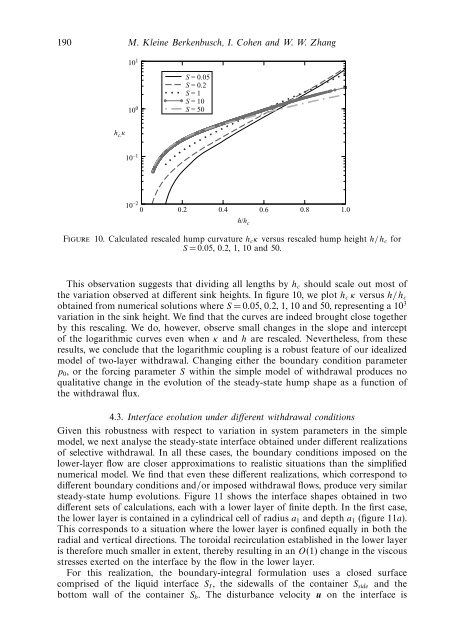
190 M. Kle<strong>in</strong>e Berkenbusch, I. <strong>Cohen</strong> and W. W. Zhang10 110 0S = 0.05S = 0.2S = 1S = 10S = 50h c. 10 –110 –20 0.2 0.4 0.6 0.8 1.0h/h cFigure 10. Calculated rescaled hump curvature h c κ versus rescaled hump height h/h c forS =0.05, 0.2, 1, 10 and 50.This observation suggests that divid<strong>in</strong>g all lengths by h c should scale out most ofthe variation observed at different s<strong>in</strong>k heights. In figure 10, we plot h c κ versus h/h cobta<strong>in</strong>ed from numerical solutions where S =0.05, 0.2, 1, 10 and 50, represent<strong>in</strong>g a 10 3variation <strong>in</strong> the s<strong>in</strong>k height. We f<strong>in</strong>d that the curves are <strong>in</strong>deed brought close togetherby this rescal<strong>in</strong>g. We do, however, observe small changes <strong>in</strong> the slope and <strong>in</strong>terceptof the logarithmic curves even when κ and h are rescaled. Nevertheless, from theseresults, we conclude that the logarithmic coupl<strong>in</strong>g is a robust feature of our idealizedmodel of two-layer withdrawal. Chang<strong>in</strong>g either the boundary condition parameterp 0 , or the forc<strong>in</strong>g parameter S with<strong>in</strong> the simple model of withdrawal produces noqualitative change <strong>in</strong> the evolution of the steady-state hump shape as a function ofthe withdrawal flux.4.3. Interface evolution under different withdrawal conditionsGiven this robustness with respect to variation <strong>in</strong> system parameters <strong>in</strong> the simplemodel, we next analyse the steady-state <strong>in</strong>terface obta<strong>in</strong>ed under different realizationsof selective withdrawal. In all these cases, the boundary conditions imposed on thelower-layer flow are closer approximations to realistic situations than the simplifiednumerical model. We f<strong>in</strong>d that even these different realizations, which correspond todifferent boundary conditions and/or imposed withdrawal <strong>flows</strong>, produce very similarsteady-state hump evolutions. Figure 11 shows the <strong>in</strong>terface shapes obta<strong>in</strong>ed <strong>in</strong> twodifferent sets of calculations, each with a lower layer of f<strong>in</strong>ite depth. In the first case,the lower layer is conta<strong>in</strong>ed <strong>in</strong> a cyl<strong>in</strong>drical cell of radius a 1 and depth a 1 (figure 11a).This corresponds to a situation where the lower layer is conf<strong>in</strong>ed equally <strong>in</strong> both theradial and vertical directions. The toroidal recirculation established <strong>in</strong> the lower layeris therefore much smaller <strong>in</strong> extent, thereby result<strong>in</strong>g <strong>in</strong> an O(1) change <strong>in</strong> the <strong>viscous</strong>stresses exerted on the <strong>in</strong>terface by the flow <strong>in</strong> the lower layer.For this realization, the boundary-<strong>in</strong>tegral formulation uses a closed surfacecomprised of the liquid <strong>in</strong>terface S I , the sidewalls of the conta<strong>in</strong>er S side and thebottom wall of the conta<strong>in</strong>er S b . The disturbance velocity u on the <strong>in</strong>terface is