Liquid interfaces in viscous straining flows ... - Itai Cohen Group
Liquid interfaces in viscous straining flows ... - Itai Cohen Group
Liquid interfaces in viscous straining flows ... - Itai Cohen Group

Create successful ePaper yourself
Turn your PDF publications into a flip-book with our unique Google optimized e-Paper software.
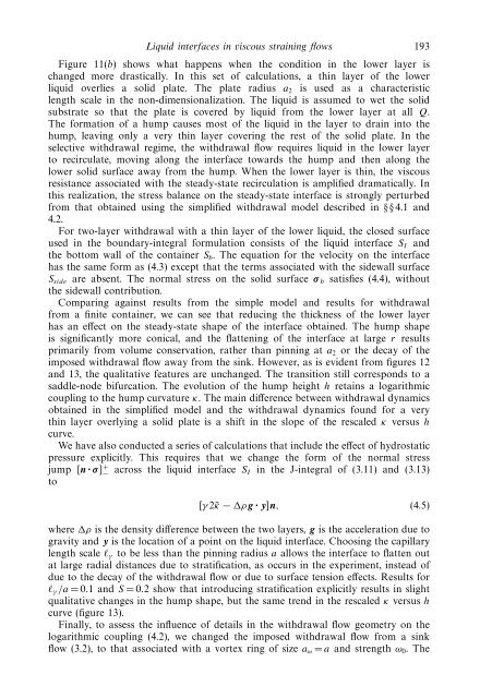
<strong>Liquid</strong> <strong><strong>in</strong>terfaces</strong> <strong>in</strong> <strong>viscous</strong> stra<strong>in</strong><strong>in</strong>g <strong>flows</strong> 193Figure 11(b) shows what happens when the condition <strong>in</strong> the lower layer ischanged more drastically. In this set of calculations, a th<strong>in</strong> layer of the lowerliquid overlies a solid plate. The plate radius a 2 is used as a characteristiclength scale <strong>in</strong> the non-dimensionalization. The liquid is assumed to wet the solidsubstrate so that the plate is covered by liquid from the lower layer at all Q.The formation of a hump causes most of the liquid <strong>in</strong> the layer to dra<strong>in</strong> <strong>in</strong>to thehump, leav<strong>in</strong>g only a very th<strong>in</strong> layer cover<strong>in</strong>g the rest of the solid plate. In theselective withdrawal regime, the withdrawal flow requires liquid <strong>in</strong> the lower layerto recirculate, mov<strong>in</strong>g along the <strong>in</strong>terface towards the hump and then along thelower solid surface away from the hump. When the lower layer is th<strong>in</strong>, the <strong>viscous</strong>resistance associated with the steady-state recirculation is amplified dramatically. Inthis realization, the stress balance on the steady-state <strong>in</strong>terface is strongly perturbedfrom that obta<strong>in</strong>ed us<strong>in</strong>g the simplified withdrawal model described <strong>in</strong> §§4.1 and4.2.For two-layer withdrawal with a th<strong>in</strong> layer of the lower liquid, the closed surfaceused <strong>in</strong> the boundary-<strong>in</strong>tegral formulation consists of the liquid <strong>in</strong>terface S I andthe bottom wall of the conta<strong>in</strong>er S b . The equation for the velocity on the <strong>in</strong>terfacehas the same form as (4.3) except that the terms associated with the sidewall surfaceS side are absent. The normal stress on the solid surface σ b satisfies (4.4), withoutthe sidewall contribution.Compar<strong>in</strong>g aga<strong>in</strong>st results from the simple model and results for withdrawalfrom a f<strong>in</strong>ite conta<strong>in</strong>er, we can see that reduc<strong>in</strong>g the thickness of the lower layerhas an effect on the steady-state shape of the <strong>in</strong>terface obta<strong>in</strong>ed. The hump shapeis significantly more conical, and the flatten<strong>in</strong>g of the <strong>in</strong>terface at large r resultsprimarily from volume conservation, rather than p<strong>in</strong>n<strong>in</strong>g at a 2 or the decay of theimposed withdrawal flow away from the s<strong>in</strong>k. However, as is evident from figures 12and 13, the qualitative features are unchanged. The transition still corresponds to asaddle-node bifurcation. The evolution of the hump height h reta<strong>in</strong>s a logarithmiccoupl<strong>in</strong>g to the hump curvature κ. The ma<strong>in</strong> difference between withdrawal dynamicsobta<strong>in</strong>ed <strong>in</strong> the simplified model and the withdrawal dynamics found for a veryth<strong>in</strong> layer overly<strong>in</strong>g a solid plate is a shift <strong>in</strong> the slope of the rescaled κ versus hcurve.We have also conducted a series of calculations that <strong>in</strong>clude the effect of hydrostaticpressure explicitly. This requires that we change the form of the normal stressjump [n · σ ] + − across the liquid <strong>in</strong>terface S I <strong>in</strong> the J-<strong>in</strong>tegral of (3.11) and (3.13)to[γ 2˜κ − ρ g · y]n, (4.5)where ρ is the density difference between the two layers, g is the acceleration due togravity and y is the location of a po<strong>in</strong>t on the liquid <strong>in</strong>terface. Choos<strong>in</strong>g the capillarylength scale l γ to be less than the p<strong>in</strong>n<strong>in</strong>g radius a allows the <strong>in</strong>terface to flatten outat large radial distances due to stratification, as occurs <strong>in</strong> the experiment, <strong>in</strong>stead ofdue to the decay of the withdrawal flow or due to surface tension effects. Results forl γ /a =0.1 andS =0.2 show that <strong>in</strong>troduc<strong>in</strong>g stratification explicitly results <strong>in</strong> slightqualitative changes <strong>in</strong> the hump shape, but the same trend <strong>in</strong> the rescaled κ versus hcurve (figure 13).F<strong>in</strong>ally, to assess the <strong>in</strong>fluence of details <strong>in</strong> the withdrawal flow geometry on thelogarithmic coupl<strong>in</strong>g (4.2), we changed the imposed withdrawal flow from a s<strong>in</strong>kflow (3.2), to that associated with a vortex r<strong>in</strong>g of size a ω = a and strength ω 0 .The